-
Assignment
Input DevicesInput Devices
In this week assignment, we have to use and test different input devices. That means I have to determain what are the input devices in general and what are the input devices that can be used with hello world board I did a couple of weeks ago
As my final project (robot) needs some sensors for obtining variables from environment
I will use three main sensors as inputs, the first one is tilt sensor, the second one is utrasonic sensor, the third one is line tracker sensor
Reference to the data sheet and the pin digram of the attiny44 which the hello board circuit was built based on

By looking at Attiny44 pin diagram and reading the data sheet
The following pin numbers can be used as input/output (5,6,7,8,9,10,11,12,13). And 4 of them can generate PWM (Pulse Width Modulation) which is basically variable output voltage between 0 and 5 volts to control the brightness of LED or the speed of the motor ..ect.
What I planned to test first is tilt sensor, this sensor senses the tilt as it has a small conductive ball inside and it closes the path or opens it based on the position of the object

It’s a digital sensor that returns the signal while tilted.
What I have here is a sensor module, that has 3 terminals: VCC which is 5 volts, GND which is ground, and D0 which is the signal that should be connected to one of the input pin of Attiny44 microcontroller board.

By checking the microcontroller board that I have done, there is no specific headers for the input/output pins, because some of them are connected either to ISP pins or FTDI terminals. But instead of soldering new cables or taking new terminals the board might look not good, so I’m going to use the pins that connected to the arduino to receive the programming just after transfering the code.

I prepared the code to program the tilt sensor module

In the void setup, I did identification for two main pins, one is 7 for output which is LED and the other one is 4 for input which is tilt sensor module.
pinMode(7, OUTPUT); the function pinMode takes 2 arguments the first one is the pin number, the second one is the status wither is INPUT or OUTPUT.
In the void loop, I started by creating new variable to keep the sensor status, HIGH or LOW because it’s digital sensor, so, there is no third option.
Then , and to know the status of the sensor, I added a condition that checks the variable x status if it’s high the LED turns on if not the LED turns off. I’m using the LED that soldered already exists on the board.
After doing the code, I connected Attiny44 board to Arduino by using 6 wires as I did in week 9 (Embedded programming)

By selecting the board (Attiny44), I uploaded the code successfully
Once the code is uploaded, I disconnected the arduino directly and connected the sensor module accordingly. Finally connected the FTDI cable to energize the board

Note: the pin that I selected to be as an input is ADC4 which is pin number 9 by referring to the datasheet or the pins diagram above
Now the sensor is working perfectly and the LED is working accordingly
I can also set the sensor sensitivity by turing the potentiometer that exists on the sensor module

The second sensor that I tested this week is ultrasonic sensor. It’s basically distance sensor that can detects the obstacle distance in front of it (how far is it?)

As shown in the above figure, the sensor transmits the ultrasound wave, the wave reflects when it hits the object and then the sensor receives the wave once again. So, the speed of the wave is known (approximately 343 m/s) and the time is known as well but we should divide it by 2 because of going and getting back time. Then the distance = ½ * time * speed
I prepared the code to be uploaded
Sometimes and to simplify the code, the developers make libraries include functions to call whenever you want. Here I included simple library instead of make the calculations. The library Ultrasonic.h allowed me to measure the distance in one command which is ultrasonic.read()
So, I’m going to use 3 pins ( one for built in LED and the others for the ultrasonic sensor). The code is basically compared the distance with 15 cm. If the distance is less than 15 cm so the object get closer and the LED turns on, otherwise, the LED is off
I connected the board to Arduino to transfer the programming, I uploaded the code then disconnected the wires
I connected the circuit as the ultrasonic sensor has 4 pins:


VCC: connected to 5v
GND: connected to ground
Trig: connected to pin number 9 which is ADC4 as output
Echo: connected to pin number 7 which is ADC6 as input

Finally, I connected the FTDI cable to energize the board and see what is happening
Line tracker sensor: This sensor has LED and phototransistor, the LED emits the light and the phototransistor receives the light as an input So, the sensor knows the black and white based on the amount of light and the reflection parameters. Comparing the brightness of the light is when placed on either a black or white surface. I will use this sensor in the final project to detect the path and follow it

Our global mentor requested new design to meet my needs in the input and output devices. I started new microcontroller board design, I selected Attiny44 to design, as the inputs and outputs devices that I selected can be connected and programmed using this microcontroller chip. I created new project using Eagle program and started collecting the components needed
I did the connection similer to what I have done in hello world board. Now I started connected the paths to do the traces done to start milling process

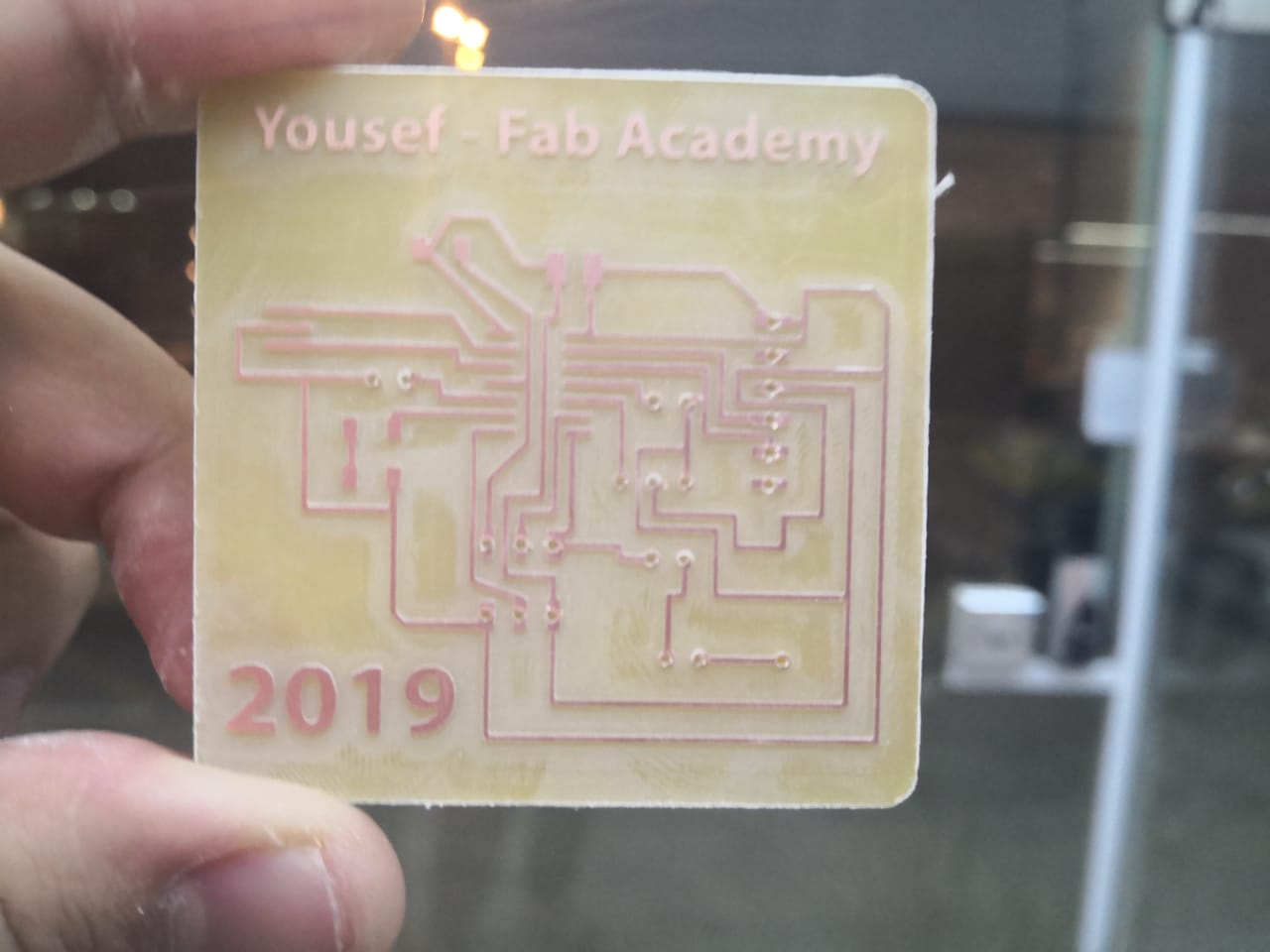
I got the board ready after milling, drilling and cutting
I started the soldering process with the microcontroller chip, Attiny44
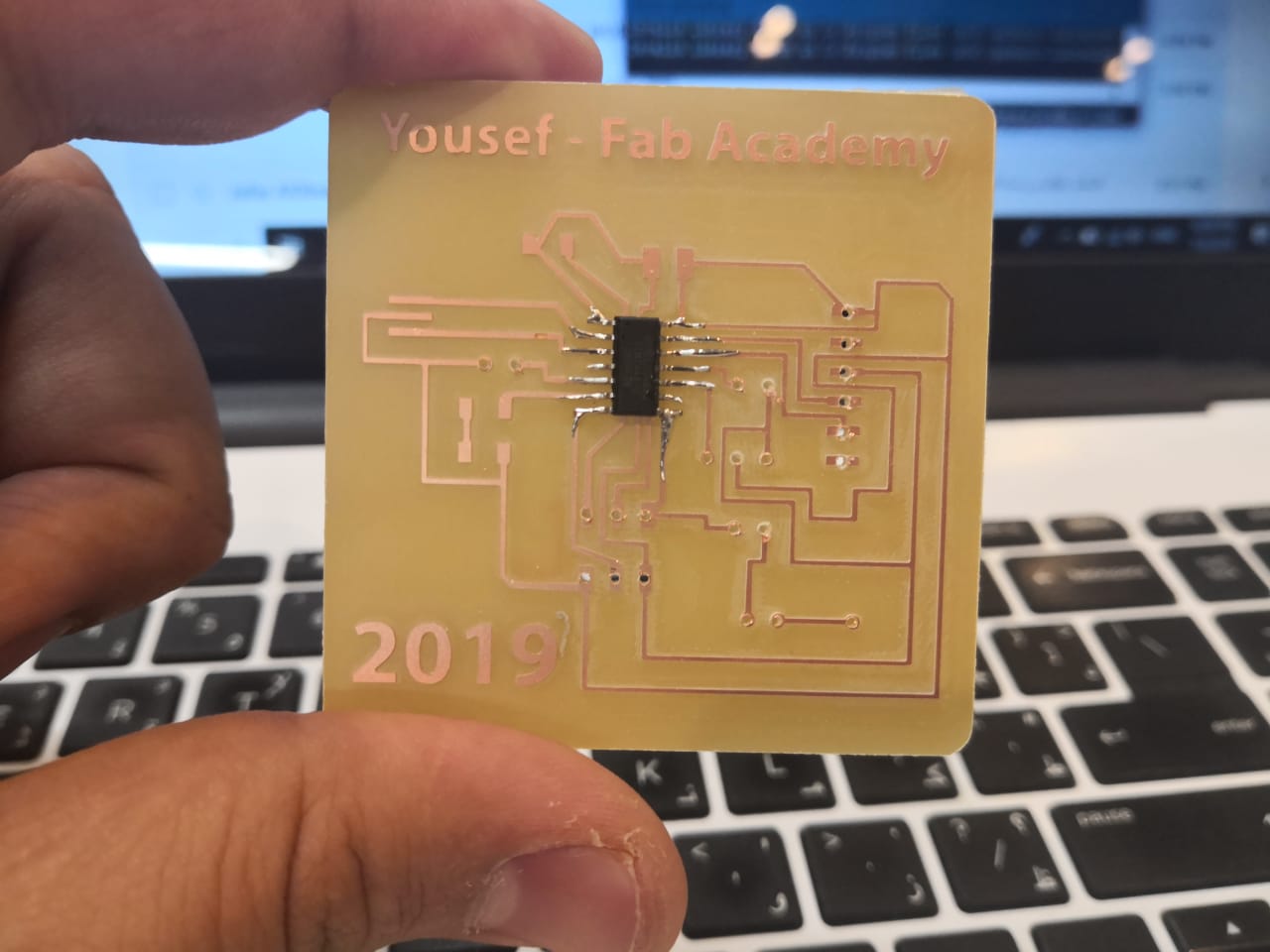
I complete the soldering process
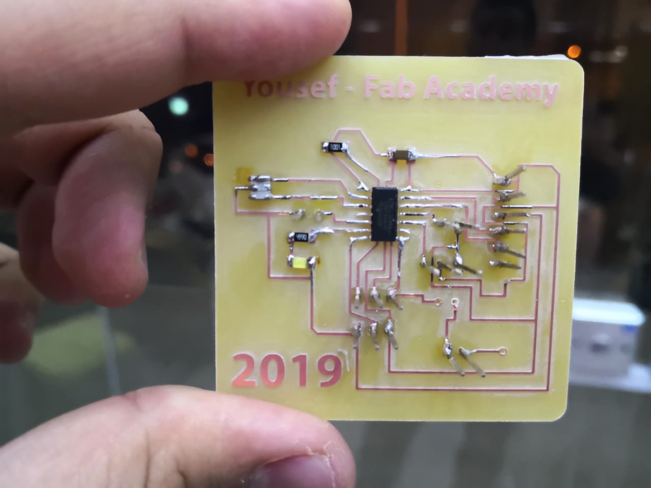
I added the final components which are the power transistor and diode
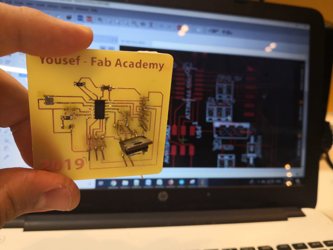
I tested the board using multimeter before I start program it. I'm planning to use an Arduino as ISP to transfer the code to my board. I tested the code by uploading blinking code (my LED is connected to pin 7)
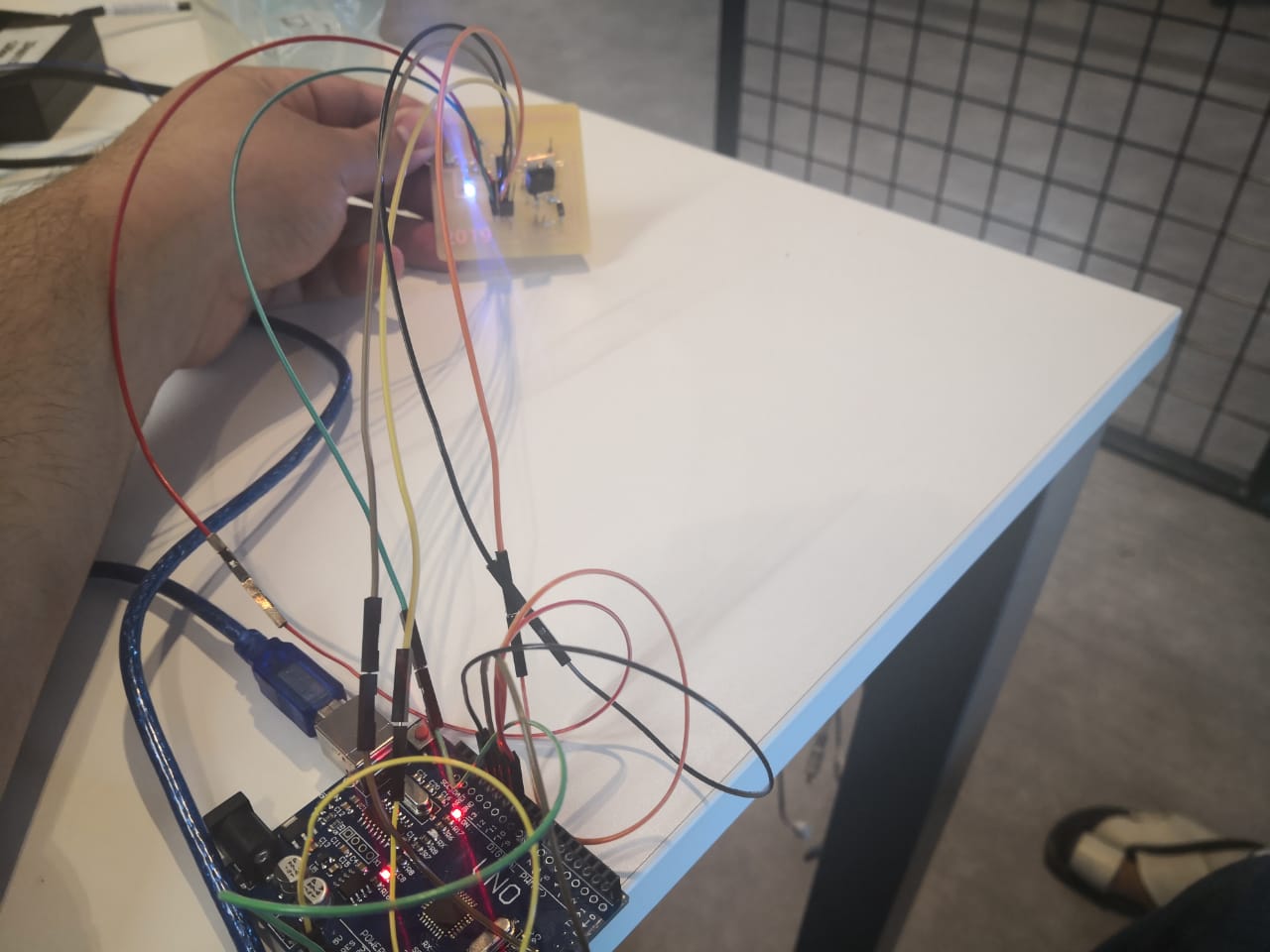
I connected the first sensor which is tilt sensor and uploaded the code, I changed the pin only to pin 3 as shown in the digram
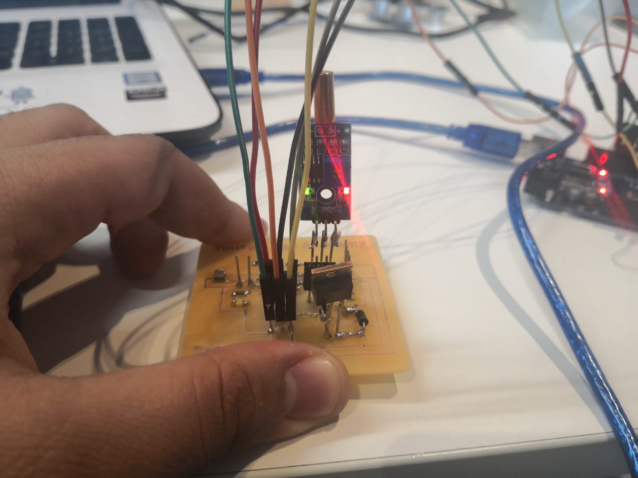
I recorded a video to show the working
The next sensor is ultrasonic sensor, I considered the pins as PA2 triger and PA8 echo. I connected the sensor and uploaded the code by consedering the pins 2 and 8
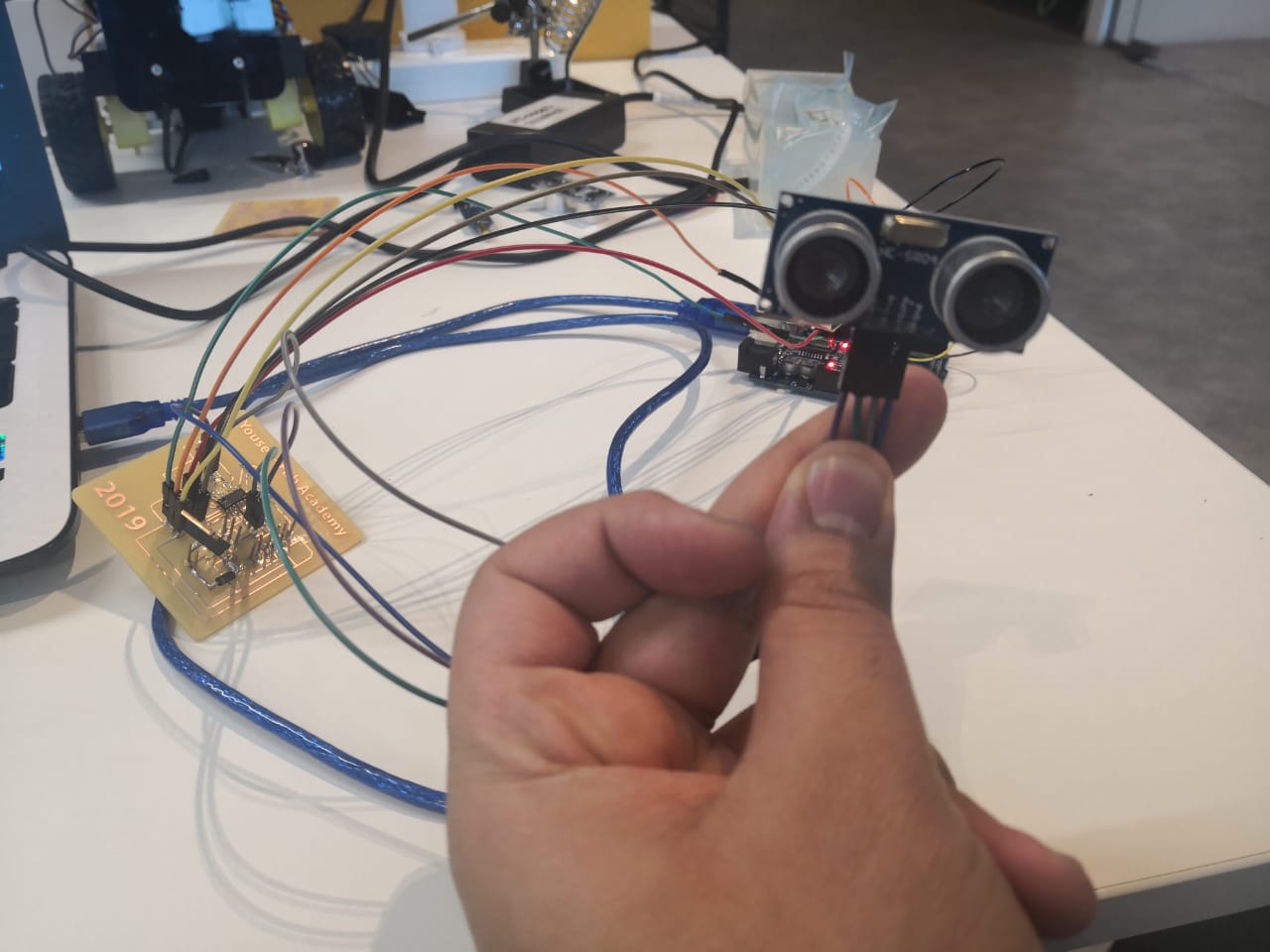
I recorded a video to show the working
Download files:
Tilt sensor code here
Ultrasonic code here
Eagle board design here
References: