-
Final Project
Smart Warehouse RobotI started working on the final project by impelementing project plan to see the big picture and what are the milestones and tasks that should be done
Trying to finish the bill of material to prepare the parts, I did the list as the following:
you can download the Excel sheet with prices and links by
So, starting with the first milestone which is fabricating the robot chassis and then will document the milestones one by one to finish all the steps that I’m planning to work on
1st milestone: Fabricating the robot chassis:I did the initial design a couple of weeks ago in the computer aided design week and cut it in the computer controlled week using acrylic 3mm with laser cutter

But the acrylic does not have that flexibility when fixing the motors as it cracks immediately. I cut more than one time but the result the same even when I made the motor circle bigger because I was planning to make it fit as possible. By starting editing the design especially the part where the motors will be fixed
It’s better to have the part where the motor will be fixed 3D printed because I can control the material thickness and the material itself as well. We have here different types of 3D filament, one of them called PETG (polyethylene terephthalate glycol-modified) which is the perfect filament to combine strength and ductility, which is why it’s used in so many mechanical parts and robotics. I modified the design to be printed by prusa 3D printer. I extruded the edges except the place of motors and the wires collections I extruded the base to be 8mm
And the outer lines to be 23mm, so, I can fix the motors with screws as well easily
Here, I faced many problems, when I exported the design as stl, and drop it in prusa sli3er it, an error was shown as the following
The error message is (Auto repaired (2110 errors)). And to fix the errors I had to click right click on the error message. But after fixing the error, the design changed completely. I tried many times but the results are the same. I did some research and asked my friends who have experience in this, and finally I recognized that I was extruding the lines which is not correct at all. So, I got back to the sketch to draw a closed rectangular instead of couple of outer lines. It worked fine!
The base model is ready to be printed, I set the settings through the program which is prusa Sli3er. I selected the filament generic PET as I was planning to print using PETG. I changed the extruder temperature for the first layer and other layers as it is written in the filament that I have to be 230C and 240C
The printing process has started just after exporting the g code and transferring the file to SD card
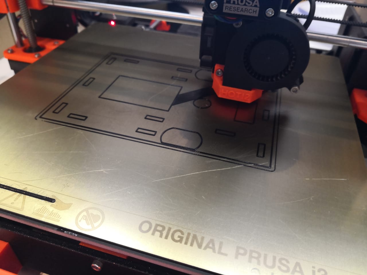
I was watching the printing process to make sure that the settings are good
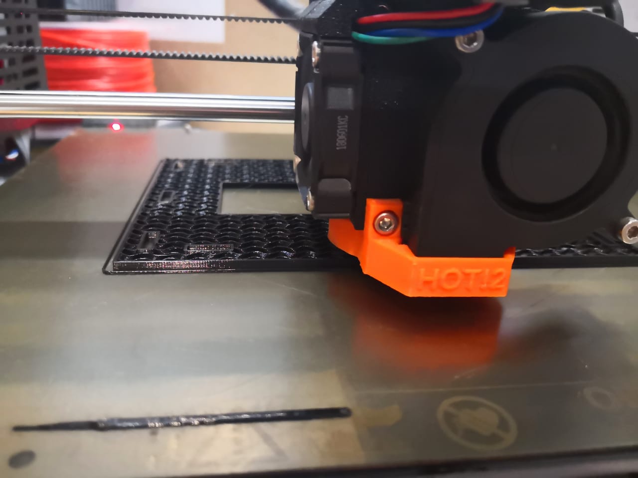
After printing the model out, I tried to fix the motors but they did not fit their places perfectly
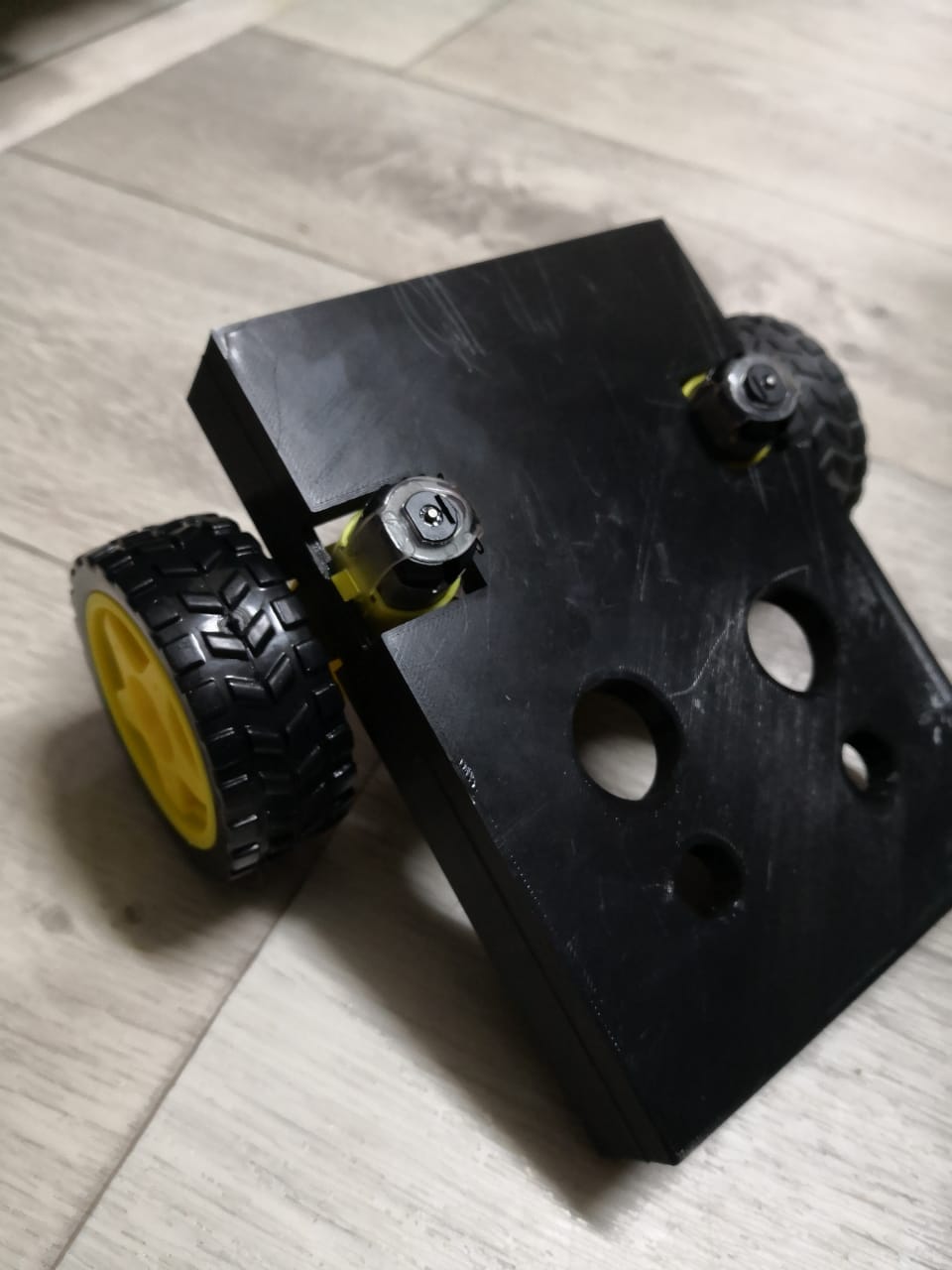
I had to use dremel and try to push them many times, the space is very tight and the motors were not stable and in balance situation
I felt that the design needs to be changed and amended with new dimensions
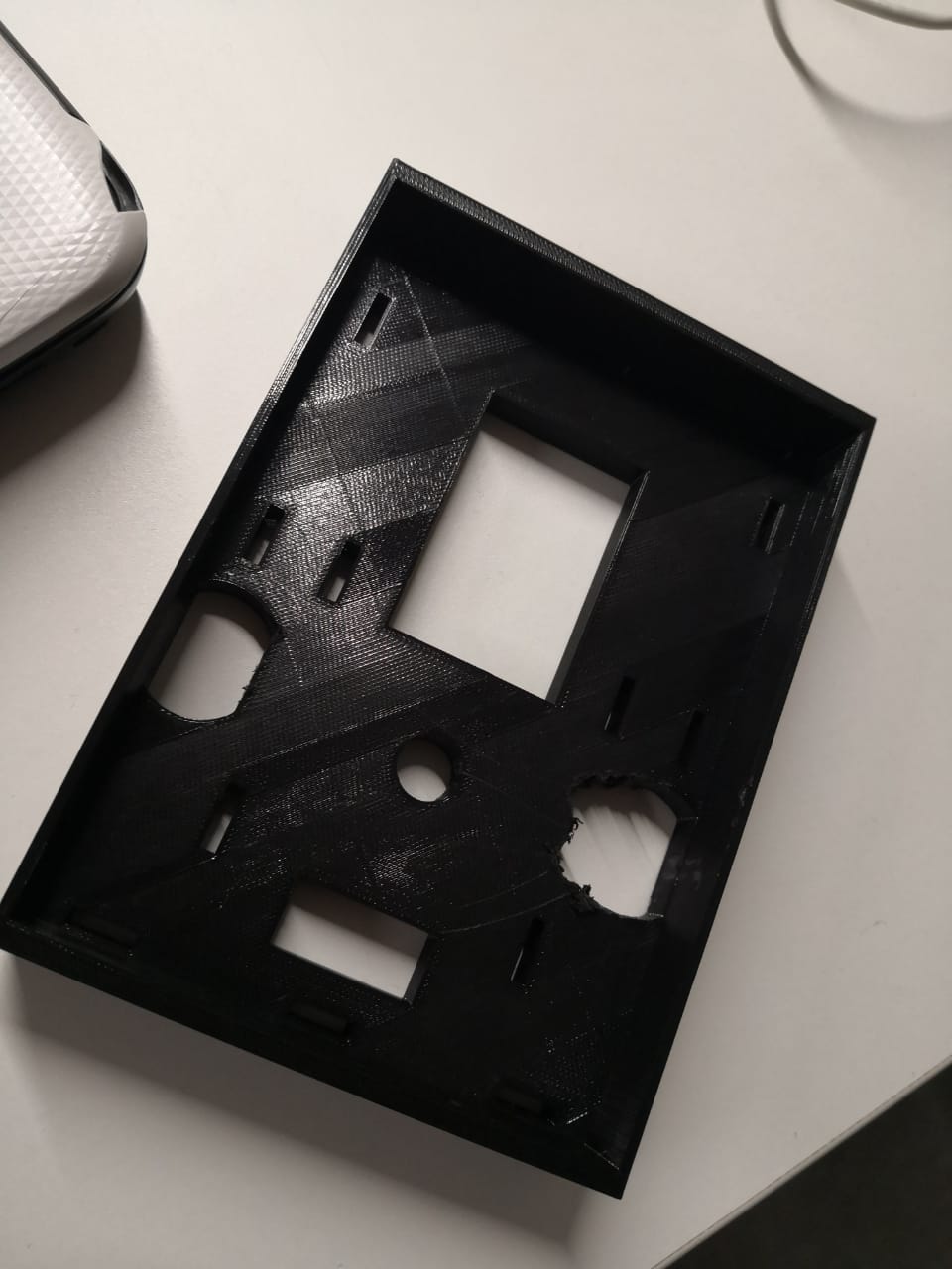
I created a new document in Onshape to design something similar to what I was designed and suitable for the robot requirements. I started the project by hide all the planes and keep the top to create the sketch. The top plane was selected to do the first sketch, I added the rectangular and edited the dimensions to be 108mm * 150mm and then and as I was going to extrude the edges I used the offset tool to create a copy of the outer edge with 3mm space to be connected and being closed loop to be able to extrude. I used digital caliper to measure the motors dimensions to make the suitable places. I did all the sketches in one side, to use mirror tool after that to mirror everything to take the same positions as I selected the mirror lines reference to be in the middle of the rectangular. The other holes are created to fix some other components like electronics stuff
By selecting the main rectangulare to be 8mm extruded
I did the same thing for the outer closed loop that was created by the offset with 3mm space, and to be 23mm extruded
As the robot will move, the motors should have high level of stabilization and fix with balance to be able to move. So, I created new sketches at the side plane to do the space to put screws in order to fix the motor as the motors that I have here have two holes that can be used for fixing by screws and nuts
By doing the same thing but different sketch plane to be on the other side, then, I selected them and clicked on extrude, but this time I selected remove, to make the subtract on the material itself
It was removed by 3mm because the material thickness was set 3mm. I was planning to use IR sensors to do the tracking, So, I considered this and made new sketch on the front chassis plane to do the holders and add the front balance for the robot instead of adding new wheels or motors. I used digital caliper to measure the sensor with holes where I can fix it, the sensors should be close to the ground to detect the path that should take
Clicked on the sketch fillet icon to make the edges smooth to reduce the friction especially while robot moving. I extruded the sketches by 4mm
On the other side, I was planning to fix 16*2 LCD screen with push buttons to be as control panel where the user can interface and interact simply with the robot to be user friendly. I created a new sketch in the plane and did 2 holes and used mirror to copy them one more time
And by removing the material at the holes, from extrude tool by 3mm
Now, the design is ready
I exported the model as stl and drop it in Prusaslicer, and checked the settings as I was going to use PETG. I did slice and export as G-code to start printing. The printing process went smoothly without any problem
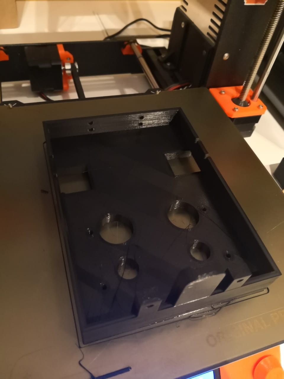
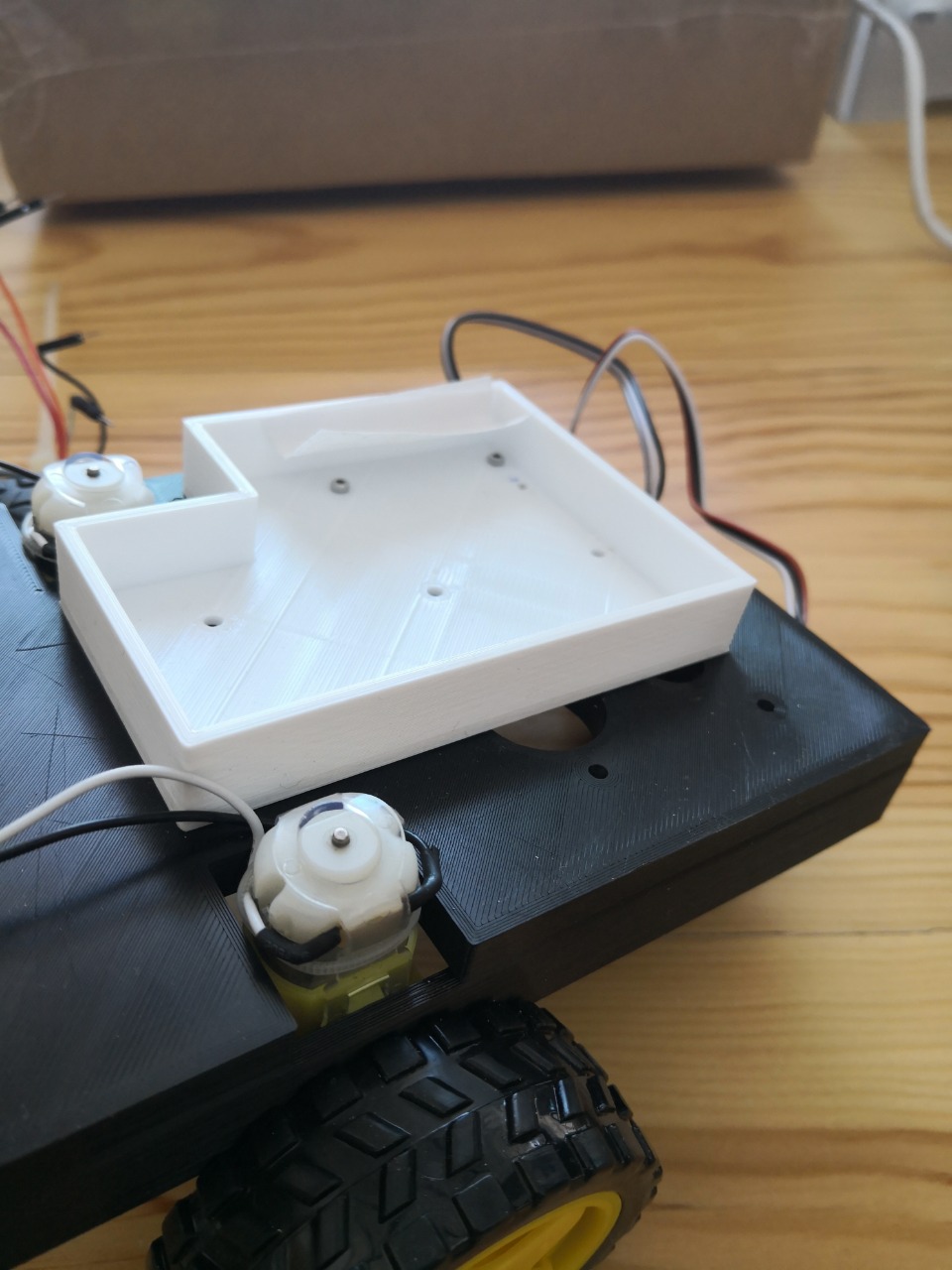
I started designing board holder where I can fix the electronics board and drivers. I tried to utilize the space on the top of the chassis to cover as much components and boards as I can. The space between the motors is narrow but the other side wider. I did a simple sketch based on the measurement that I took by using digital caliper
By copying the design and rotate the sketch that I have done, this looks really good (I shifted the design because of the picking mechanism that I’m planning to design and will be fixed on the two small holes) I did the holes to fix the boards and the model with chassis
Using the extruding tool to extrude the inner loop by 2mm and outer loop by 15mm to get the design ready
Now, exporting the design as stl and using Prusaslicer to prepare the printable form which is Gcode. The printing process went smoothly and done
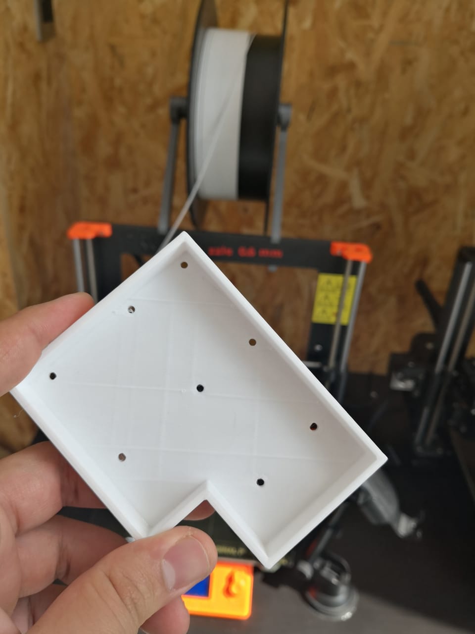
I recorded video as time-lapse to record and document the process
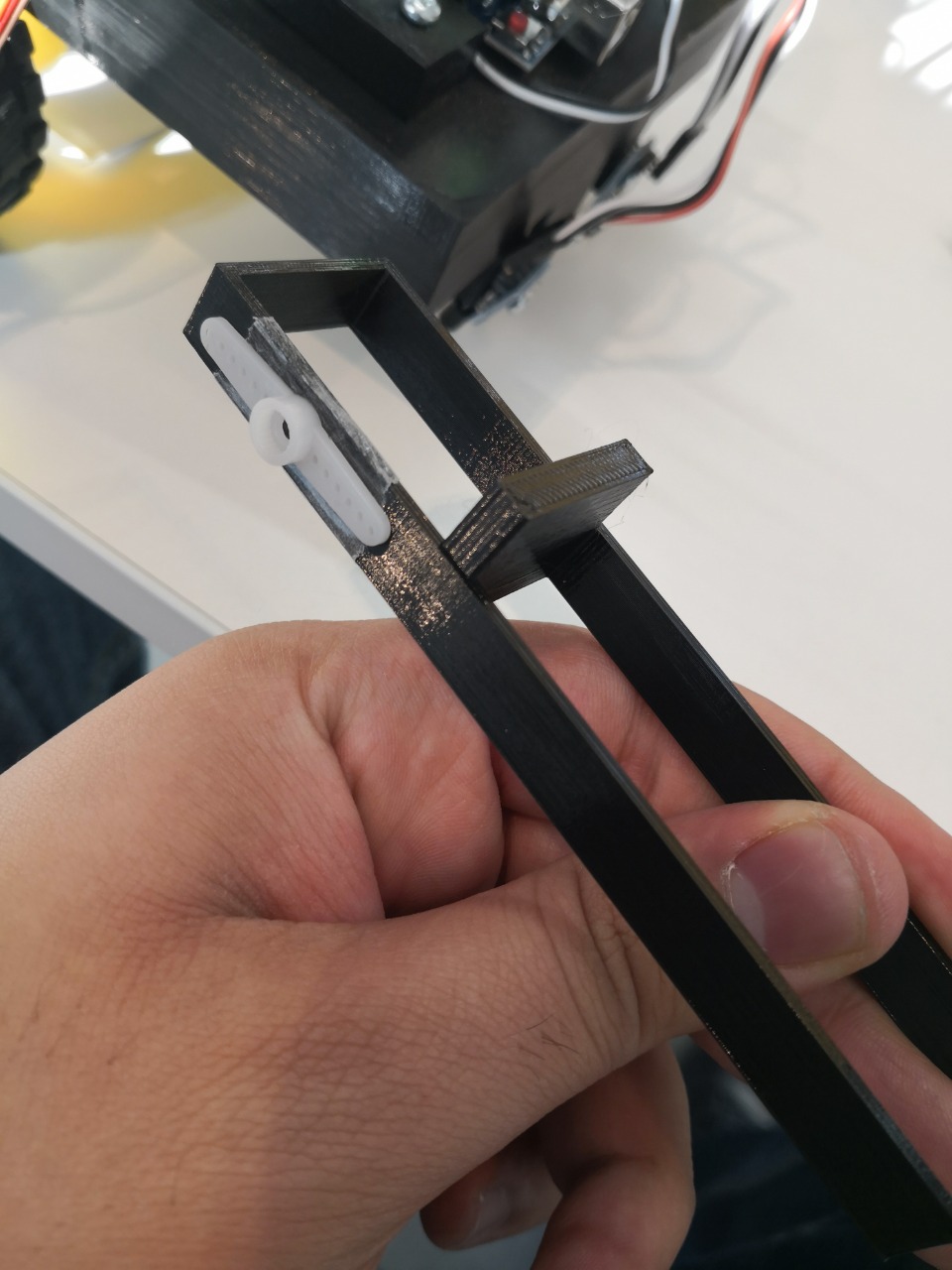
As I was planning to make picking up mechanism, I created new design to do a simple one to pick the box up. My thought is to build arm robot with servo to carry the boxes once reaching to the point. I started doing the arm itself, the part that will move and carry the box. I added a wall to make sure that the box will not be thrown away
Then, I extruded the sketches to form the arm
By extruding the parts, I got the design that I was thinking to make, then I moved to design the servo holder, to fix the servo and make sure it will not move during the arm movement, I used digital caliper to measure the hole that I need to fit the motor with screw. Then I extruded the part to get the model
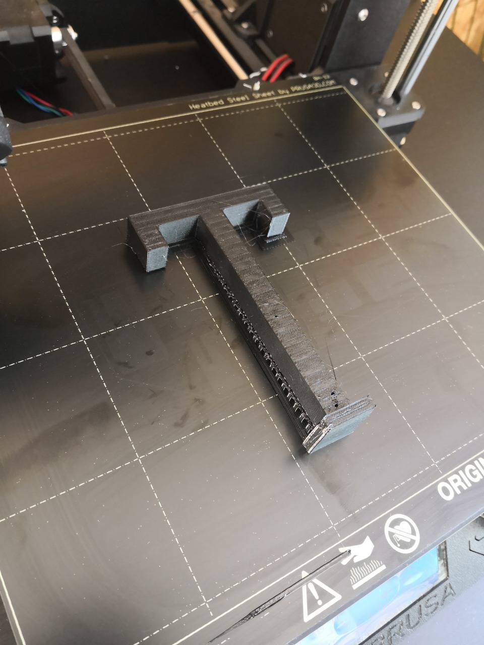
To make a simple box, I’ve designed something like T letter to be used as material box to test while finalizing the robot. So, now everything is ready in terms of mechanism to carry the boxes
Now, the plan is to build a simple user interface, where the user can interact with the project. To build that I need to design a simple holder for the LCD 16*2 and push buttons. I used inkscape after getting the measurement to build that. The buttons are not good to be used as they are, I will design something to be clear and better shape to press
The design needs several holes, for LCD, push buttons, and to fix the part in main robot. I was planning to do something with laser cutter and bend it using heat bender. Creating new design in Inkscape, then adding rectangular with circle to be merged later
To union the two shapes, I select union after selecting them, then i got the main shape
The part will be bent from the merging line where the rectangular and circle intersection. To make the LCD position, I used digital caliper and took the dimensions and then I added new rectangular with holes around to fix the LCD
Adding new rectangulares for the push buttons, to be designed later
I added the space where I will fix the part and attach it to the robot chassis. Now the design is ready to cut
The plan now is to make the design of push buttons. I started doing that by using Onshape, the measurements are recorded from the spaces that I made in the LCD and push buttons holder. When designing something like that, I had to consider the user experience while the button is pressed, to be easy and friendly to use. I did it as two parts, the first one is designed to fit the hole in the holder and from one direction and the button from another. The second part is designed to fit the first part and be movable and to push it by the user
By assembling the parts using Onshape to make sure the design is fit and complete using some tools such as fasten
from differnt views
I started printing the parts using Full Spectrum laser cutter and Prusa 3D printer and then fixing them together
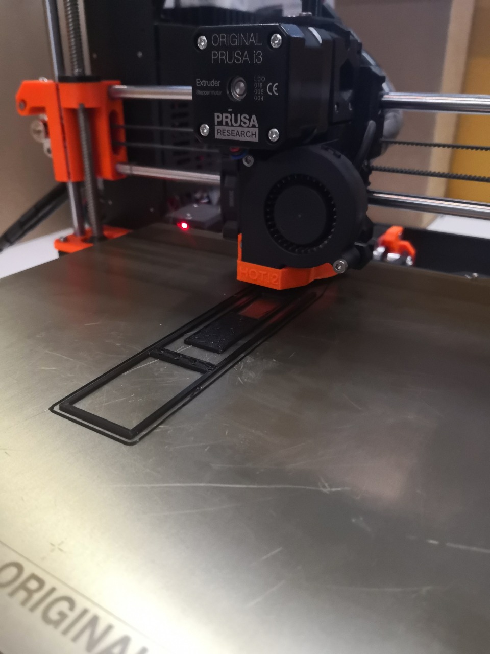
Printing the sample of material or box, using PETG and Prusa 3D printer
Fixing the micro servo motor and attach it in place using screws to make sure that it’s well attached and will not move during the working. Also, fixing the part with robot chassis using two screws from the top of the chassis where the holes placed
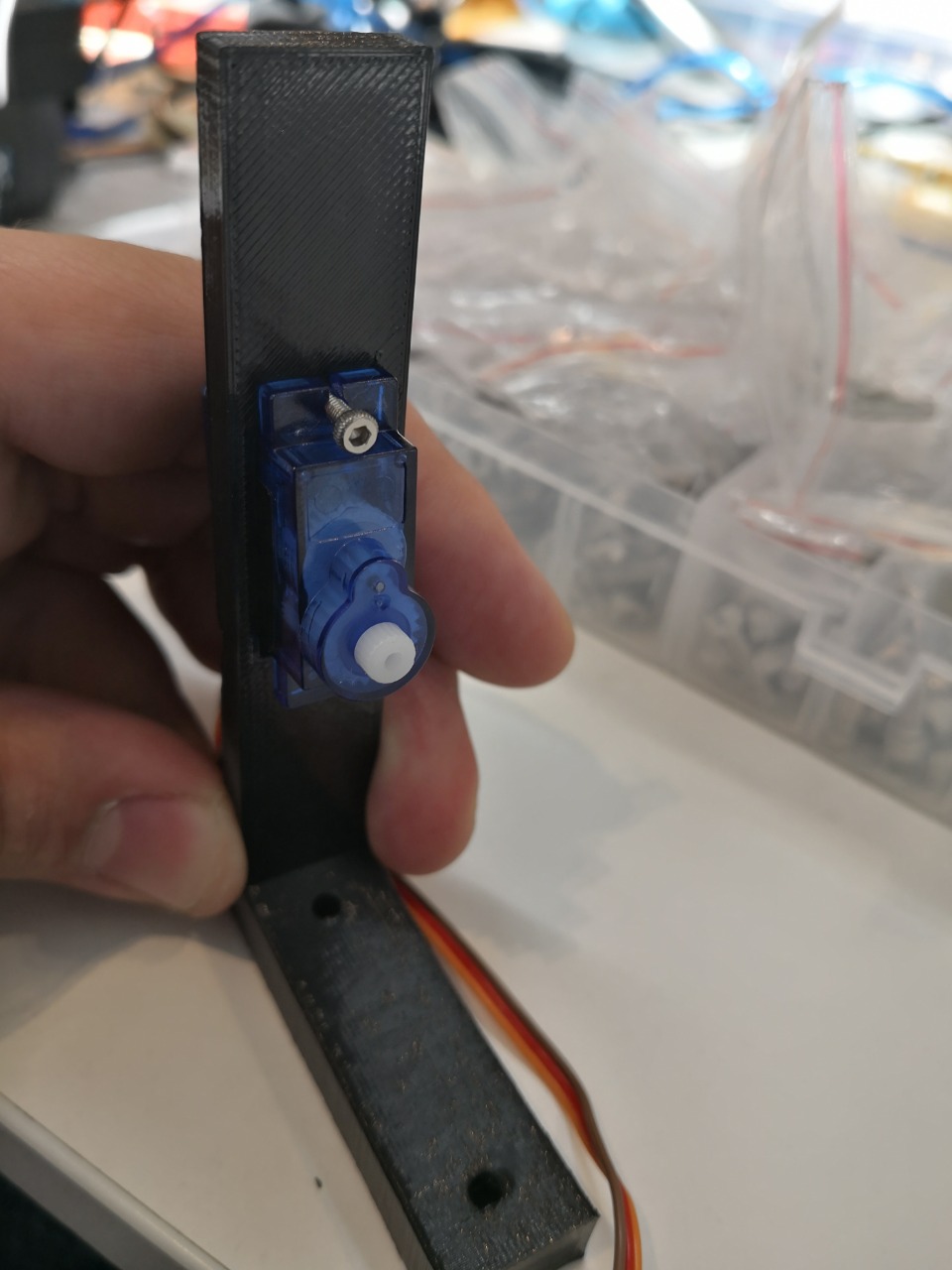
Using double sided tape to attach the part to move while servo motor moves to carry the material needed
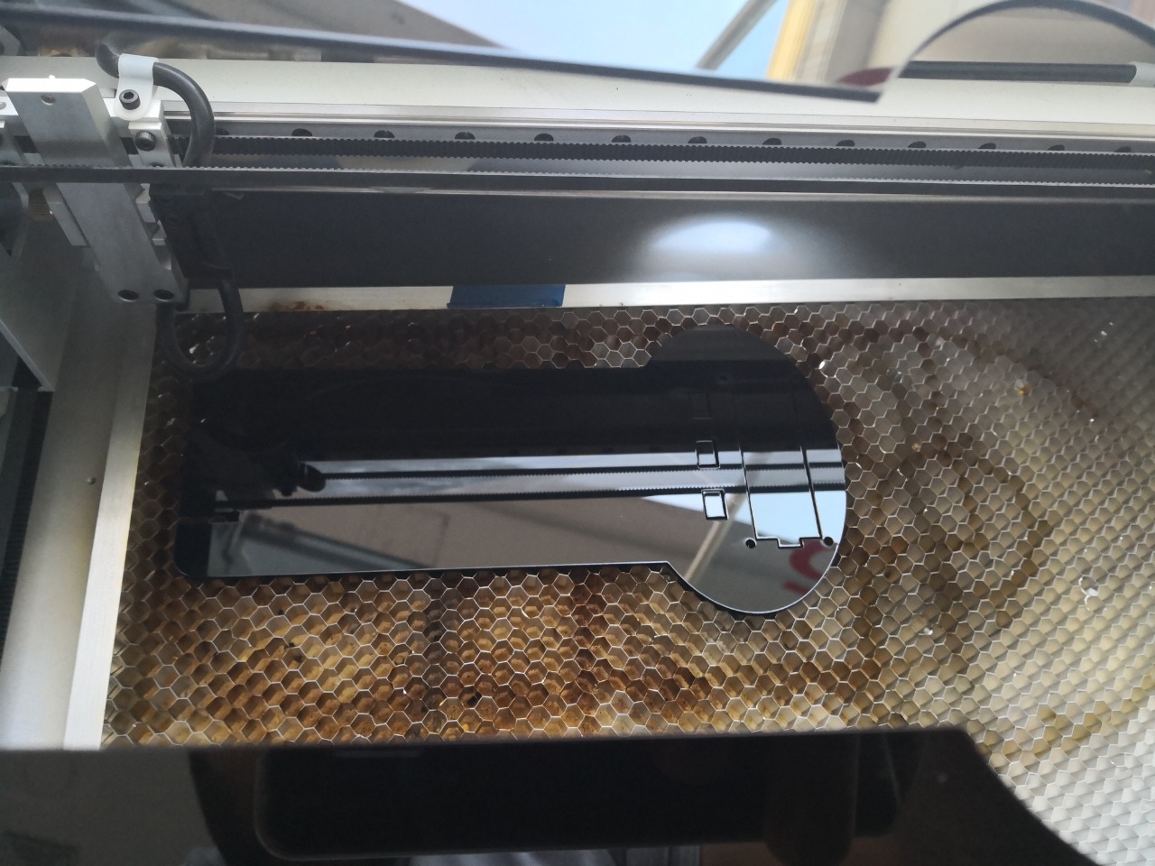
Cutting the LCD and push buttons holder using laser cutter and black acrylic 3mm, I set the power and speed in Retinaengrave software, the power: 100, Speed: 8
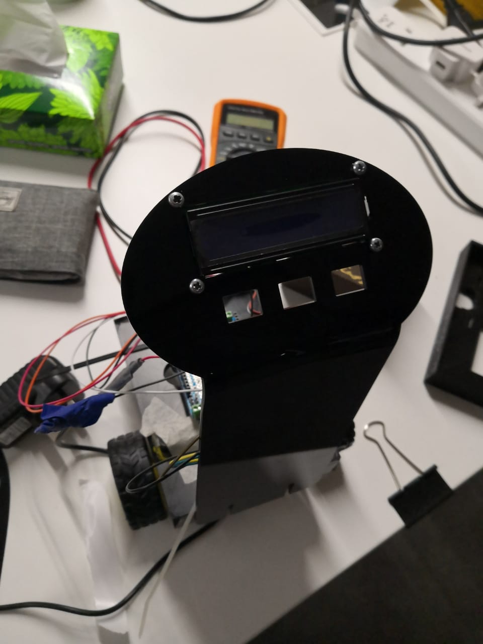
The part is ready now, but I need to bend it to be suitable and in front of the user directly while using
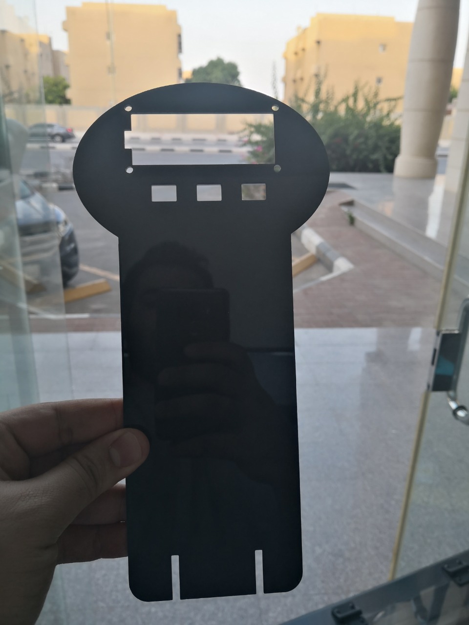
I did bend it using heat gun at 380 degrees, it was nice process as it should be perfect bended and looks nice, I fixed it using black tape on the table. It took a while to form again with strong shape

The chassis has to have the electronics board and components fixed on it, I used the screws to fix both of them at the places where I did holes. The two DC motors were fixed as well, each one by two screws as the places where considered during the designing process
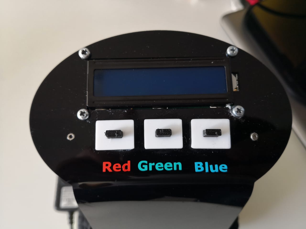
The holes were considered in designing the LCD and push buttons holder to fix the LCD, push buttons, and the part itself with the robot chassis. By using screw driver with some screws, I finished fixing it
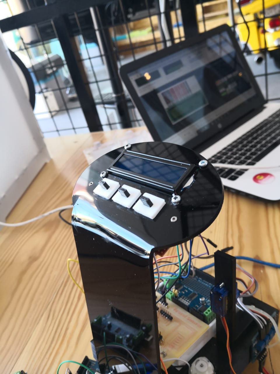
I printed out the push buttons using two different colors by 3D printer. I tried to make them fit but I had to use a little super glue to make them well fixed, because the user should push them always, it should be user friendly and strong enough
The buttons should be clear for the user, to select the right path, Therefore, I was planning to make stickers using Vinyl cutter to be placed where the buttons are. I did a simple design containing 3 words (Red, Green, Blue) and cut them using vinyl cutter, each word in the same color to explain the word itself. I have vinyl cutter called GCC expert || 24
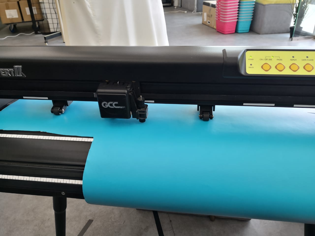
To get them you have to use tweezers, especially because they are too small. After removing the additional sticker surrounded by the design, I used transfer tape to take off the word and place it where they should be

Trying to document the process by recording short video
The robot is almost ready now in terms of building the parts and fixing them together, after adding the stickers to finalize the structure
2nd milestone: Electronics production:To make sure that the electronics that I'm going to design would work well and before I design and mill the board, I had to test the components using ready microcontroller board such as Arduino. They are a number of steps I'm planning to achieve to create the features of the robot.
1- Creating a control board for users to be able to communicate with the robot
2- Controlling the motors
3- Following the line (path)
4- Picking the box
I tried the above mentioned steps using Arduino to ensure system working before moving into designing, milling, and soldering processes
1- Creating a control board for users to be able to communicate with the robot It’s all about connecting LCD (liquid crystal display) screen and push buttons to control the robot movement and make user friendly interface. I started connecting the LCD reference to arduino website tutorial

Basically I used 6 digital pins from Arduino to make the communication between LCD 16*2 and Arduino to show the text. Then, I connected 3 push buttons with pull-down resistors (to limit the current and protect the Arduino). The pins that I used are 6,7,8 as the signal is digital ethir high or low. These pins will be considered as inputs
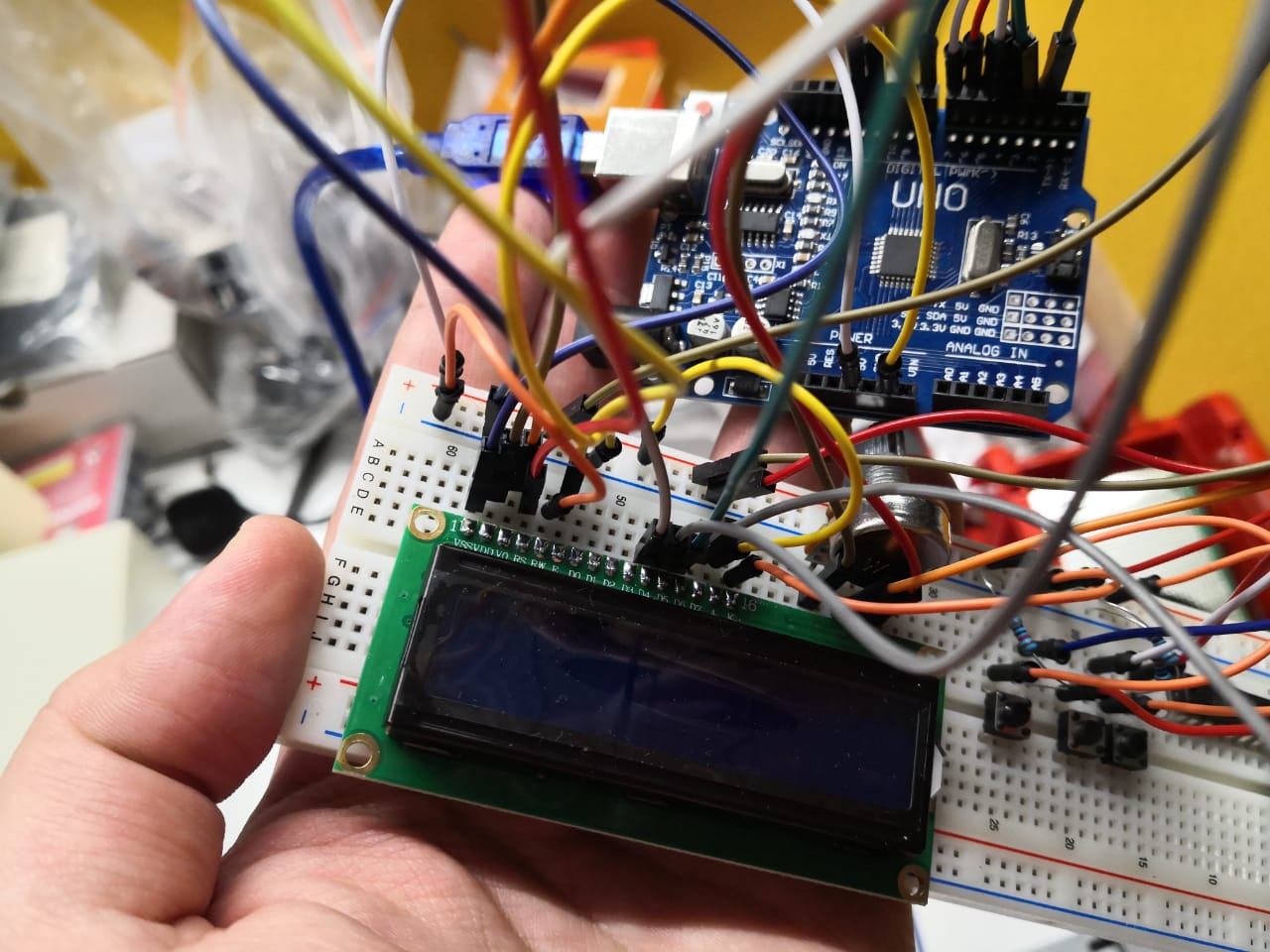
After I complete wiring up the circuit I open Arduino IDE to write the code. What I planned to do is a simple interface that shows what the status of the robot. The push buttons are considered to represent 3 different paths (3 types of boxes) which are red boxes, blue boxes and green boxes. Once the user selects one of them, the robot should take the path of selected boxes. The code that I prepared is:
#include < LiquidCrystal.h>

int Green;
int Blue;
int Red;
const int rs = 12, en = 11, d4 = 5, d5 = 4, d6 = 3, d7 = 2;
LiquidCrystal lcd(rs, en, d4, d5, d6, d7);

void setup() {
  pinMode(6,INPUT);
    pinMode(7,INPUT);
  pinMode(8,INPUT);


  lcd.begin(16, 2);
  lcd.print("Hello! This is");
  lcd.setCursor(0, 1);
  lcd.print("Warehouse Robot");
}

void loop() {
  Green = digitalRead(6);
   Blue = digitalRead(7);
   Red = digitalRead(8);

   if(Green == 1){

    lcd.clear();
    lcd.print("Robot is heading");
  lcd.setCursor(0, 1);
  lcd.print("to green boxes");

   }

      if(Blue == 1){

    lcd.clear();
    lcd.print("Robot is heading");
  lcd.setCursor(0, 1);
  lcd.print("to blue boxes");

   }


      if(Red == 1){

    lcd.clear();
    lcd.print("Robot is heading");
  lcd.setCursor(0, 1);
  lcd.print("to red boxes");

   }


}
Liquid crystal library is included at the beginning, to use the functions and interface under it. The code starts with showing the welcoming and robot name. The text that appeared is “Hello! This is warehouse robot” and then the user should select which box needs. So, the robot can start heading to the boxes taking the right path. The code then includes 3 main conditions, each one for each button for each path. The push button that connected to pin 6 represents green boxes, the push button that connected to pin 7 represents blue boxes, and the last push button which is connected to pin 8 represents red boxes. Once the green button pressed, the robot should head to the green boxes taking the green boxes path, and so on.
I uploaded the code successfully and checking the results, once I pressed the push button connected to pin 6 which represents the green boxes

When I pressed the push button connected to pin 7 which represents the blue boxes

When I pressed the push button connected to pin 8 which represents the blue boxes

The video showing overall results
2- Controlling the motors I have adafruit motor shield that can drive 4 DC motors or 2 stepper motors in addition to 2 servo motors
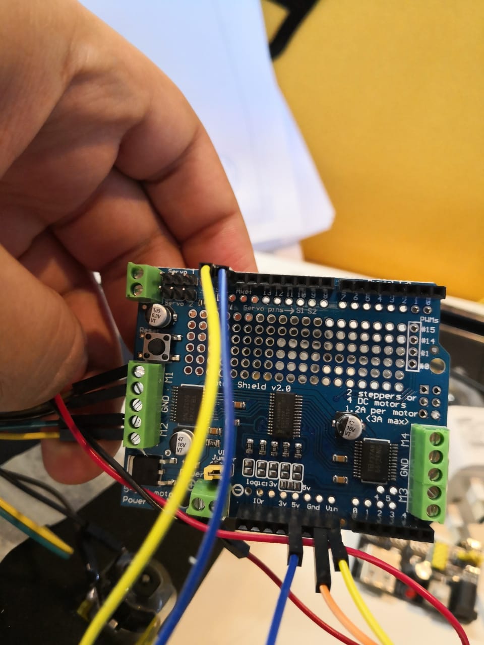
The shield uses 2 main pins from Arduino, which are SDA and SCL
The shield has 2 IC’s to control the motors, each IC has 2 H-brides. H-bridge is a simple connection where we can control the motors direction (forward and backward). Each H-bridge can drive 1.2A maximum

As for the speed, it can be controlled using PWM (pulse width modulation) from the microcontroller. I started connecting the circuit, I have two 5V DC motors which I connected them in M1 and M2
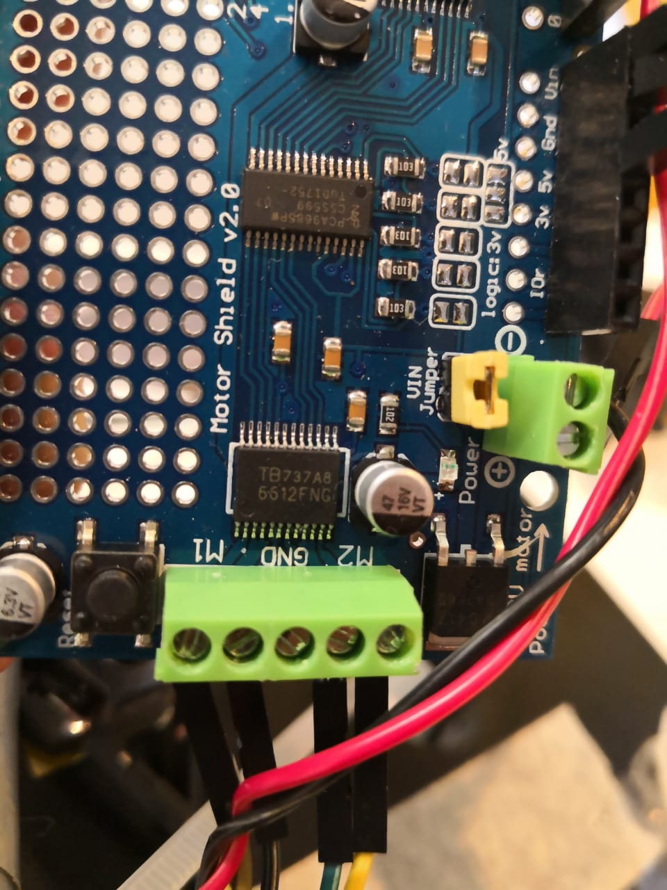
The motor wiring in this case did not matter as I can change the rotation direction from the code itself. The shield has a yellow jumper, this used to select which power supply energized what. If the jumper is connected, the two boards (Arduino and motor shield) will have the same power supply (if any one is connected, the other one runs accordingly). If the jumper is not connected, each board has different power supply as the sources are not connected (I can power the Arduino up using USB cable and the board using lipo battery or power bank or any power source provides 5v and minimum of 1.5A )
I included the library that can interface the motor shield which called “Adafruit Motor shield V2 library” from the arduino software, by clicking on Sketch >> include library >> manage libraries and then typing “Adafruit Motor shield V2”
I can use the library now to test the motors, I did simple code to be uploaded and tested. It’s easy to use by simple commands such as:
myMotorright->setSpeed(150); // to set the speed, it’s allowed between 0 to 255, 255 represents the max. speed
  myMotorright->run(FORWARD); //either forward or backward, so you can set the direction
Attaching the shield to the Arduino, to start programming and controlling the motors. I’m going to test DC motors, there are 4 positions, each one has a number to call in the code. It’s printing on the shield as well, from M1 to M4. I used M1 and M2 to test the two motors that I have
I opened the example that is included in the library, called DCMotorTest, and understood the commands to make simple one and test the motors that I have, I got the following code
#include < Wire.h>
#include < Adafruit_MotorShield.h>

// Create the motor shield object with the default I2C address
Adafruit_MotorShield AFMS = Adafruit_MotorShield();
// Or, create it with a different I2C address (say for stacking)
// Adafruit_MotorShield AFMS = Adafruit_MotorShield(0x61);

// Select which 'port' M1, M2, M3 or M4. In this case, M1 and M2
Adafruit_DCMotor *myMotor1 = AFMS.getMotor(1);
Adafruit_DCMotor *myMotor2 = AFMS.getMotor(2);

void setup() {


  AFMS.begin();  // create with the default frequency 1.6KHz


}

void loop() {
myMotor1->setSpeed(150);
  myMotor1->run(FORWARD);
myMotor2->setSpeed(150);
  myMotor2->run(FORWARD);
  delay(2000);
  myMotor1->run(RELEASE);
  myMotor2->run(RELEASE);
 delay(2000);

}
The purpose of the code is to make the motors move for 2 seconds and stop for another. I used 150 speed with forward direction for both
By using an external power supply, 5v and 3A, the shield and Arduino were powered up and the motors started working perfectly according to the code
The robot should follow the line (black tape). The IR sensor (transmitter and receiver) can detect that easily. So, in general, I will run the motors to move the robot forward except once the line is detected. In this case the robot should move right or left according to the sensor that detects
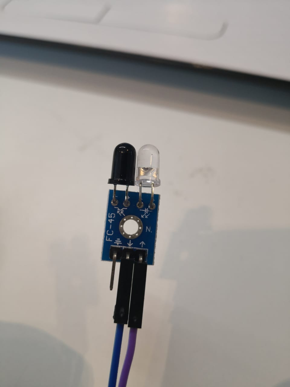
The sensor module that I have here has 3 pins. The first one is 5v, the second one is ground, the third one is signal that goes to the microcontroller. I was not sure what is the signal while detecting black color, so I tested it using the multimeter and got the result
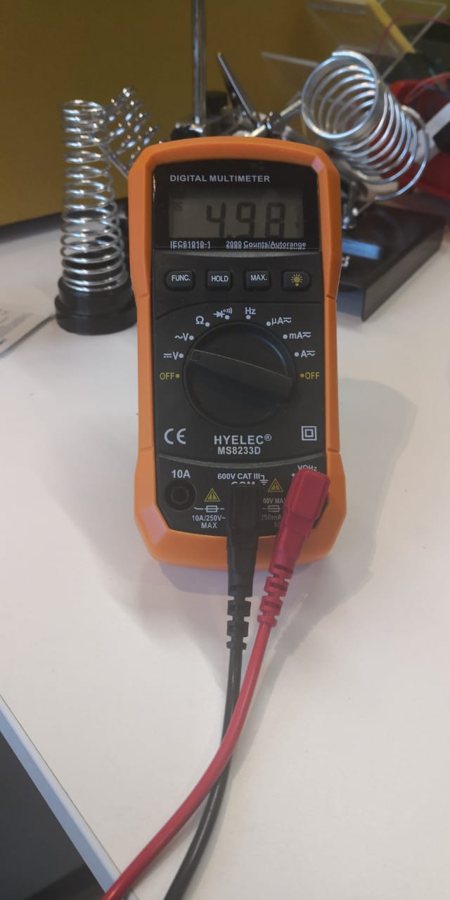
So, as I measured the voltage from signal to ground while detecting the black and the reading was around 5 volts. Therefore, the sensor is giving high if it detects black and low if there is no black
There is a number of techniques to follow the line, one of them was very simple and based on if condition. I was wondering if this would work with my system and my case. I prepared the code based on 4 main conditions:
- If no black color detected, move forward
- If the right sensor detects, move left
- If the left sensor detects, move right
- If both sensors detect, stop
The code that I did was:
#include < Wire.h>
#include < Adafruit_MotorShield.h>

Adafruit_MotorShield AFMS = Adafruit_MotorShield();


Adafruit_DCMotor *myMotorright = AFMS.getMotor(1);
Adafruit_DCMotor *myMotorleft = AFMS.getMotor(2);


int left=0;
int right=0;

void setup() {

  AFMS.begin();

}

void loop() {
left=digitalRead(3);
right=digitalRead(4);

//Moving forward
if (left==0 && right==0){
   myMotorright->setSpeed(150);
  myMotorright->run(FORWARD);
  myMotorleft->setSpeed(150);
  myMotorleft->run(FORWARD);}


  //Stop
  if (left==1 && right==1){
  myMotorright->run(RELEASE);
  myMotorleft->run(RELEASE);


  }

//Moving left
   if (left==1 && right==0){
    myMotorright->setSpeed(150);
  myMotorright->run(FORWARD);
  myMotorleft->run(RELEASE);
  }


//Moving right
if (left==0 && right==1){

  myMotorleft->setSpeed(150);
  myMotorleft->run(FORWARD);
  myMotorright->run(RELEASE);

  }


}
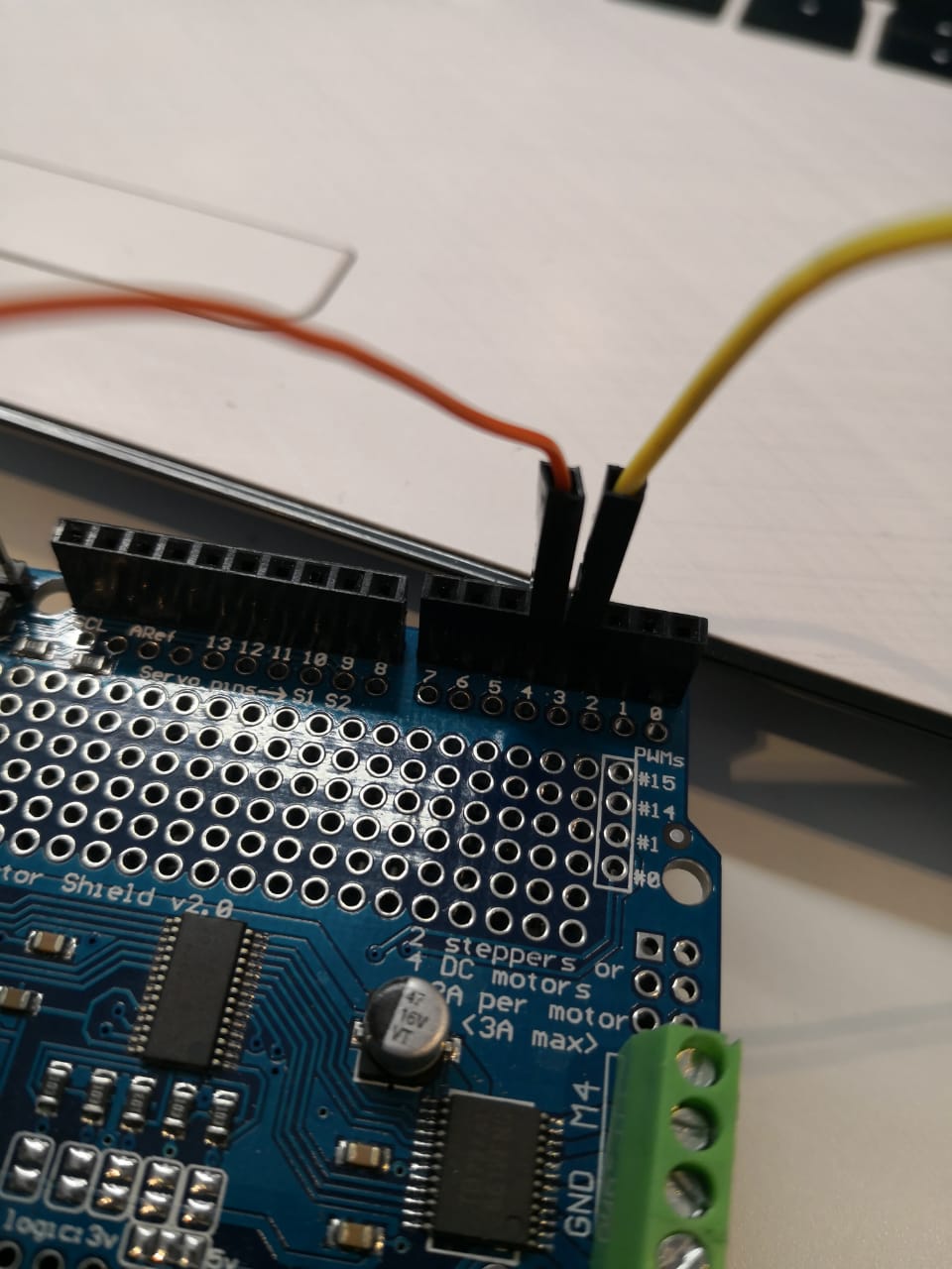
As mentioned in the code, I used pin 3 and 4 as digital pins to get the signals from the sensors (right and left) and connected them
The robot is working fine and following the line as I planned in the code
I tested the robot arm using sweep code for the servo motor, it worked good
The robot test seems fine, I need to build my own microcontroller board that can meet my requirements. It’s important to list the number of inputs and outputs to select the right microcontroller chip. The components that I need are listed already, but I need to now how many pins needed to connect all of them together with one microcontroller. The components and pins needed are:
- LCD screen: 6 pins
- Push buttons: 3 pins
- Motor shield: 2 pins (SCL and SDA)
- IR sensor module: 2 pins
- Servo motor: one pin
So, the total pins needed are 14 as input or output. I checked the microcontrollers available and used before for such applications, one is very common that called Atmega 328p from Atmel

As shown above, the microcontroller has more than 14 pins for inputs/outputs. So, I started designing the microcontroller board based on it. I created a new project using Eagle software and created a new schematic under it. After a quick research, I have to use at least 3 components with Atmega328p to start uploading the code correctly. The components are 100 nF capacitor, 1 uF capacitor, and 10 kohm resistor. So the total component that I need to add and solder later are:
- Atmega328p
- 100 nF capacitor
- 1 uF capacitor
- 10 kohm resistor
- Headers (for: inputs/outputs, ISP, VCC, GND, FTDI)
I added the components and connect them together in the schematic page (I tried to take all the I/O pins because maybe I need to connect something new adding more features or something). I used labels to organize the connections
Then I moved to the board by clicking on the “generate/switch to board” icon, then I started organizing the paths/traces as much as I can with 14 line width to get the final one with no intersections

By hiding no need layers and exporting the file as Dxf, I prepared the file to be ready for milling and cut after using inkscape to create svg file that has vectors only. I added my name at the corner as well

And drilling part

The carvy machine that I have is capable to do this in terms of milling and drilling, I have 0.2mm end mill bit that I purchased from inventables website called PCB milling bits. I started the process by opening the software that is web-based called EASEL and fixed the copper board (6 inch * 6 inch) using double sided tape. I set the feed rate 180 mm/min and the plunge rate 90 mm/min. Milling depth is 0.1mm
After fixing the copper board and editing the settings as mentioned above, I run the machine and started the job
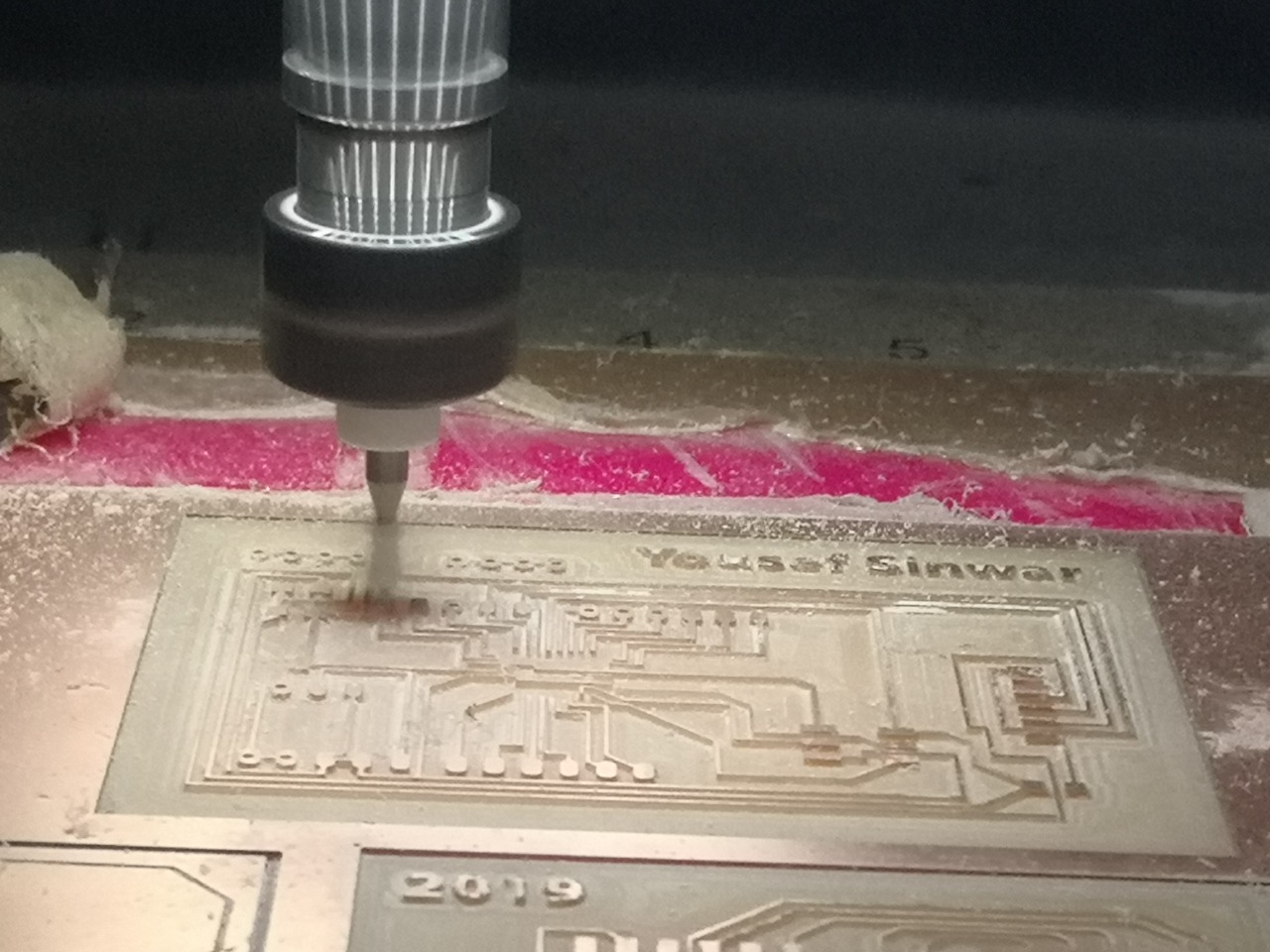
A couple of hours later and after running the drill job using 1/32” end mill bit to make the drilling and cutting, the board is ready to be soldered
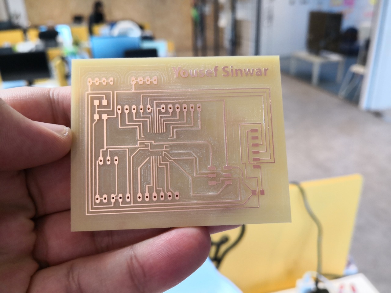
As the microcontroller is small and the pins are close to each other, I used solder paste with heat gun. To do this, I had to put a little solder paste on the board where the chip should places and by using tweezers, I could fix the chip on the copper exactly. Then I run the heat gun with 320 degrees
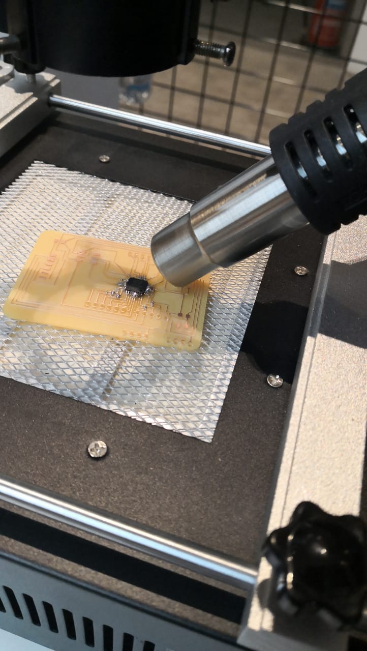
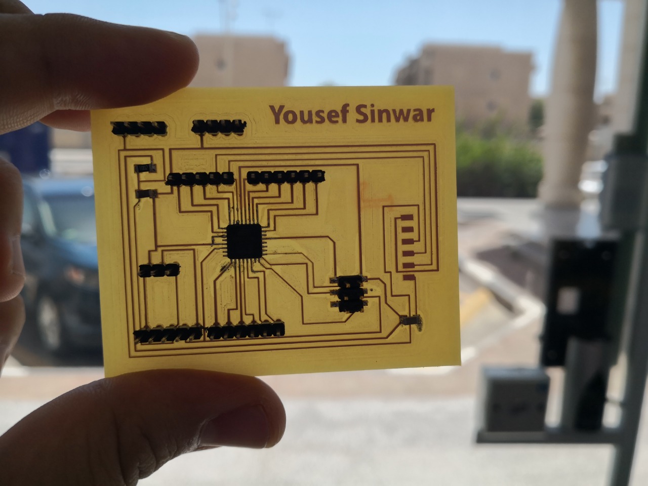
It was good to use it as the chip soldered very well and in less than 2 min just after cleaning up the additional solder paste. By using a multimeter, I checked the connection to make sure that all the pins are soldered and there is conductivity between the same lines
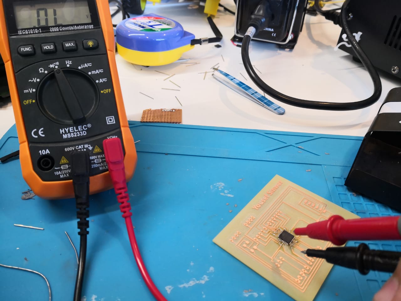
Then I finished soldering everything reference to the schematic that I designed

Now, the microcontroller board is ready to use. I tested it using simple code to make sure that it accepts the programming and no short circuit or disconnection as well. The code is
void setup() {
  // put your setup code here, to run once:
pinMode(A2,OUTPUT);
}

void loop() {

digitalWrite(A2,LOW);
delay(500);
digitalWrite(A2,HIGH);
delay(500);
}
I’m planning to use an Arduino as ISP to upload the codes. I connected the wires as I did on input devices week, I had to connect 6 wires between my board and Arduino using male to female jumpers. I opened the Arduino IDE software and select the board as ardion pro or pro mini, and the processor Atmega328 (3.3v, 8MHz) as the chip has internal crystal 8MHz. Also, selecting Arduino as ISP . The code uploaded successfully and the LED started blinking
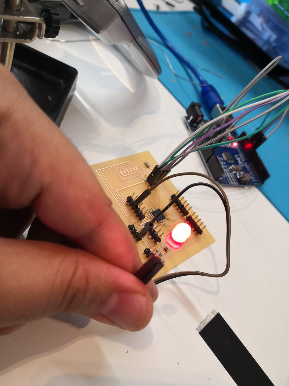
Now, and after testing the workings of the board, I need to connect my circuit. Starting with the motor shield to make sure the motors will be controlled. I connected the microcontroller board with the motor shield using 5 wires only
Microcontroller pin Motor shield pin A5 (SCL) SCL A4 (SDA) SDA VCC Vin VCC 5v GND GND
I uploaded a simple code for testing the motor working, it worked perfectly
3rd milestone: Finishing and final testing:
I finished connecting the whole thing. As for the circuit, I added the IR sensor modules, LCD, servo motor, and push buttons to the board as the following
Microcontroller pin Components’ pins 5 RS (LCD) 6 Enable (LCD) 7 d4 (LCD) 8 d5 (LCD) 4 d6 (LCD) 10 d7 (LCD) 9 Signal (servo motor) 3 Push button (green) A1 Push button (blue) A2 Push button (red) A3 IR sensor module (left) 2 IR sensor module (right) Then I was customizing the code to do the right mission, I tested as final version, it worked perfectly by selecting different paths/units. The code is
#include < LiquidCrystal.h>
#include < Wire.h>
#include < Servo.h>
#include < Adafruit_MotorShield.h>


Adafruit_MotorShield AFMS = Adafruit_MotorShield();

Adafruit_DCMotor *myMotorright = AFMS.getMotor(1);
Adafruit_DCMotor *myMotorleft = AFMS.getMotor(2);


int Green;
int Blue;
int Red;
int left=0;
int right=0;
int x=0;
int g=0;
int b=0;
int r=0;
int pos = 0;
int i=0;
int PM=0;
const int rs = 5, en = 6, d4 = 7, d5 = 8, d6 = 4, d7 = 10;
LiquidCrystal lcd(rs, en, d4, d5, d6, d7);
Servo servo1;

void setup() {
  pinMode(A0,INPUT);
    pinMode(A1,INPUT);
  pinMode(A2,INPUT);
     pinMode(A3,INPUT);
  pinMode(2,INPUT);
    pinMode(9,OUTPUT);
      pinMode(3,INPUT);


  AFMS.begin();
  lcd.begin(16, 2);
  lcd.print("Hello! This is");
  lcd.setCursor(0, 1);
  lcd.print("Warehouse Robot");
  //servo1.attach(9);

  //servo1.write(0);
}

void loop() {
  Green = digitalRead(3);
   Blue = digitalRead(A1);
   Red = digitalRead(A2);

   if(Green == 1){

    lcd.clear();
    lcd.print("Robot is heading");
  lcd.setCursor(0, 1);
  lcd.print("to green boxes");
  //servo1.write(0);
  //PM= analogRead(A0);
  //PM= map(PM,0,1023,0,255);
  analogWrite(9,41);
  g=0;

  while(g==0){
    left=digitalRead(A3);
right=digitalRead(2);


if (left==0 && right==0){
   myMotorright->setSpeed(150);
  myMotorright->run(FORWARD);
  myMotorleft->setSpeed(150);
  myMotorleft->run(FORWARD);}


  if (left==1 && right==1 && x==0){
  myMotorright->run(RELEASE);
  myMotorleft->run(RELEASE);

  delay(200);
  myMotorleft->setSpeed(150);
  myMotorleft->run(FORWARD);
     myMotorright->setSpeed(150);
  myMotorright->run(FORWARD);

  delay(180);
  myMotorleft->run(RELEASE);
  myMotorright->run(RELEASE);
  x=1;

  }

   if (left==1 && right==0){
    myMotorright->setSpeed(150);
  myMotorright->run(FORWARD);
  myMotorleft->run(RELEASE);
  }

  left=digitalRead(A3);
right=digitalRead(2);


if (left==0 && right==1){

  myMotorleft->setSpeed(150);
  myMotorleft->run(FORWARD);
  myMotorright->run(RELEASE);

  }


  if (left==1 && right==1 && x==1){
  myMotorright->run(RELEASE);
  myMotorleft->run(RELEASE);


  for(i=0; i<=14; i++){
    analogWrite(9, i);
    delay(0.1);
  }

  delay(200);
 myMotorleft->setSpeed(130);
  myMotorleft->run(FORWARD);
  myMotorright->setSpeed(130);
  myMotorright->run(FORWARD);


  delay(80);

  myMotorleft->run(RELEASE);
   myMotorright->run(RELEASE);
  x=2;

  }

  left=digitalRead(A3);
right=digitalRead(2);

  if (left==1 && right==1 && x==2){
  myMotorright->run(RELEASE);
  myMotorleft->run(RELEASE);

  delay(500);
x=0;

g=1;
lcd.clear();
    lcd.print("Hello again");
 lcd.setCursor(0, 1);
  lcd.print("Select the path");

  }
  }

   }

      if(Blue == 1){

    lcd.clear();
    lcd.print("Robot is heading");
  lcd.setCursor(0, 1);
  lcd.print("to blue boxes");
    //servo1.write(0);
analogWrite(9,41);
  b=0;

   while(b==0){

 left=digitalRead(A3);
right=digitalRead(2);


if (left==0 && right==0){
   myMotorright->setSpeed(150);
  myMotorright->run(FORWARD);
  myMotorleft->setSpeed(150);
  myMotorleft->run(FORWARD);}


  if (left==1 && right==1 && x==0){
  myMotorright->run(RELEASE);
  myMotorleft->run(RELEASE);

  delay(200);
  myMotorleft->setSpeed(200);
  myMotorleft->run(FORWARD);
     myMotorright->setSpeed(100);
  myMotorright->run(FORWARD);

  delay(150);
  myMotorleft->run(RELEASE);
  myMotorright->run(RELEASE);
  x=1;

  }

   if (left==1 && right==0){
    myMotorright->setSpeed(150);
  myMotorright->run(FORWARD);
  myMotorleft->run(RELEASE);
  }

   left=digitalRead(A3);
right=digitalRead(2);


if (left==0 && right==1){

  myMotorleft->setSpeed(150);
  myMotorleft->run(FORWARD);
  myMotorright->run(RELEASE);

  }


  if (left==1 && right==1 && x==1){
   myMotorright->run(RELEASE);
  myMotorleft->run(RELEASE);


    for(i=0; i<=14; i++){
    analogWrite(9, i);
    delay(0.1);
  }

  delay(200);
 myMotorleft->setSpeed(130);
  myMotorleft->run(FORWARD);
  myMotorright->setSpeed(130);
  myMotorright->run(FORWARD);


  delay(40);

  myMotorleft->run(RELEASE);
   myMotorright->run(RELEASE);
  x=2;

  }

    left=digitalRead(A3);
right=digitalRead(2);

  if (left==1 && right==1 && x==2){
  myMotorright->run(RELEASE);
  myMotorleft->run(RELEASE);

   delay(500);
x=0;

b=1;
lcd.clear();
    lcd.print("Hello again");
 lcd.setCursor(0, 1);
  lcd.print("Select the path");

  }


   }

   }


      if(Red == 1){

    lcd.clear();
    lcd.print("Robot is heading");
  lcd.setCursor(0, 1);
  lcd.print("to red boxes");
    //servo1.write(0);
    analogWrite(9,41);

r=0;

   while(r==0){

 left=digitalRead(A3);
right=digitalRead(2);


if (left==0 && right==0){
   myMotorright->setSpeed(150);
  myMotorright->run(FORWARD);
  myMotorleft->setSpeed(150);
  myMotorleft->run(FORWARD);}


  if (left==1 && right==1 && x==0){
  myMotorright->run(RELEASE);
  myMotorleft->run(RELEASE);

  delay(200);
  myMotorright->setSpeed(200);
  myMotorright->run(FORWARD);
     myMotorleft->setSpeed(100);
  myMotorleft->run(FORWARD);

  delay(150);
  myMotorleft->run(RELEASE);
  myMotorright->run(RELEASE);
  x=1;

  }

   if (left==1 && right==0){
    myMotorright->setSpeed(150);
  myMotorright->run(FORWARD);
  myMotorleft->run(RELEASE);
  }

   left=digitalRead(A3);
right=digitalRead(2);


if (left==0 && right==1){

  myMotorleft->setSpeed(150);
  myMotorleft->run(FORWARD);
  myMotorright->run(RELEASE);

  }


  if (left==1 && right==1 && x==1){
   myMotorright->run(RELEASE);
  myMotorleft->run(RELEASE);

    for(i=0; i<=14; i++){
    analogWrite(9, i);
    delay(0.1);
  }

  delay(200);
 myMotorleft->setSpeed(130);
  myMotorleft->run(FORWARD);
  myMotorright->setSpeed(130);
  myMotorright->run(FORWARD);


  delay(40);

  myMotorleft->run(RELEASE);
   myMotorright->run(RELEASE);
  x=2;

  }

    left=digitalRead(A3);
right=digitalRead(2);

  if (left==1 && right==1 && x==2){
  myMotorright->run(RELEASE);
  myMotorleft->run(RELEASE);

   delay(500);
x=0;

r=1;
lcd.clear();
    lcd.print("Hello again");
 lcd.setCursor(0, 1);
  lcd.print("Select the path");

  }


   }


   }


}
I tested the working, for the first path, which is green zone
Final Video that was uploaded
Final Poster

Selecting the blue zone
My project is non for profit project and licensed via creative commons platform.
I've selected Attribution-NonCommercial-ShareAlike 4.0 International (CC BY-NC-SA 4.0) license (you can check it here) As I want to make the project open for everyone who wants to improve or take a reference or do the same project
The platform has their terms and policies
Download Files' Links: