Interface and Application Programming
For this week, I will make a GUI using Processing IDE, which can be downloaded from "Click here to dowonload". I did use in this assignment the Final Project Board.
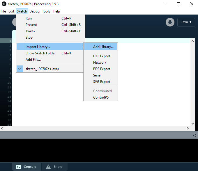
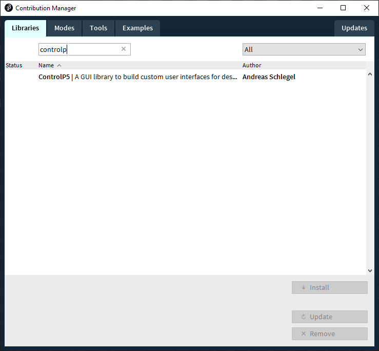
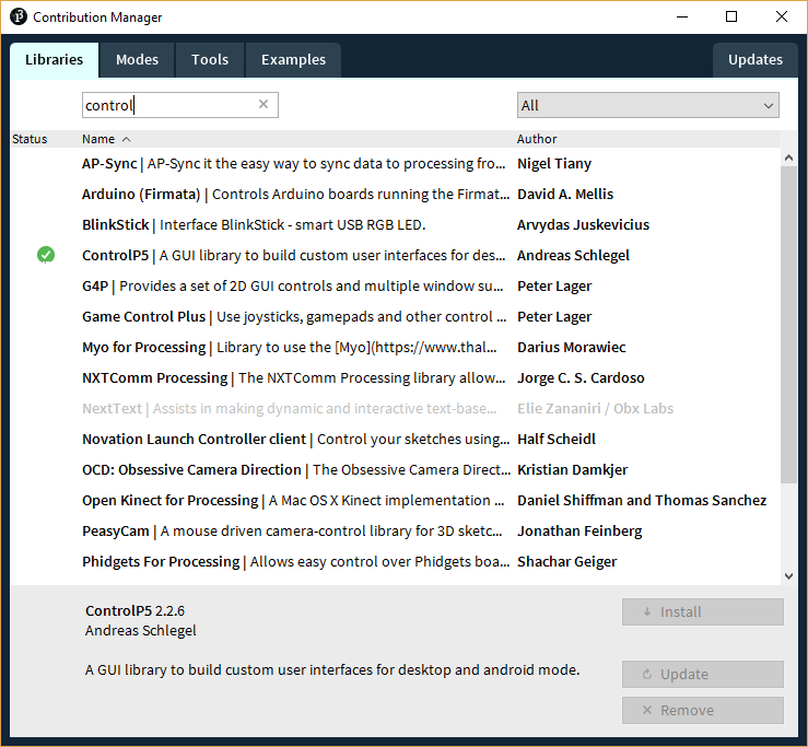
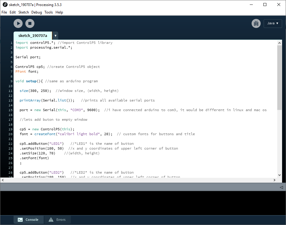
After downloading and installing the software, we can see that it looks very similar to the Arduino IDE. Similarily to arduino IDE, we need to install libraries to use certain functions. As I want to create a GUI using buttons, I will install the controlP5 library, which makes this very easy.
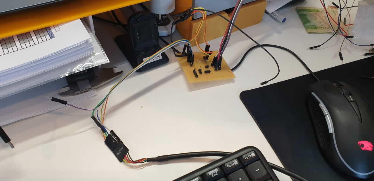
Processing runs in windows in my computer, so for my board to be able to communicate, I will use the FTDI cable. For this, I install the drivers of the cable to my computer, and then use the cable to connect to the pc.
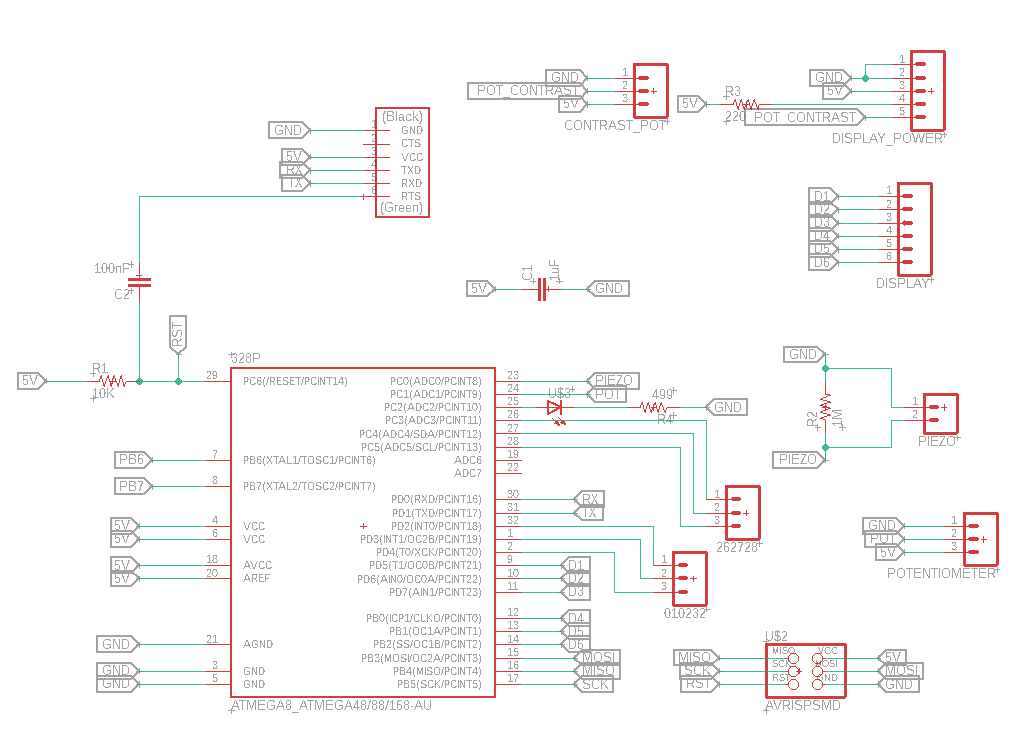
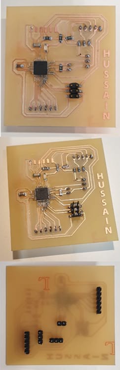
I did use the final project board in this assignment
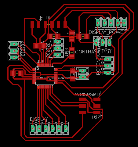
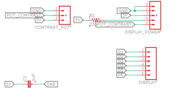
The following close-up shows the output elements
The following close-up shows the input elements. Focused on pins , 11, A2, A5, A4, A3, A1, 4, 3, 2, A0, 1, 0 and 1
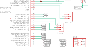
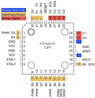
And are connected to the ATMAEGA using its pins which I found in the datasheet.
For my communication Week, I did an example of how to control RGB LED (that has common ground) in my slave board using two push buttons connected in my master board. For this week, I plan to control the RGB LED on my board, using two buttons created on my GUI. Processing will communicate with my Arduino using serial communication.
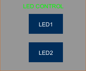
In processing, I will create 2 buttons, that will turn on the RGB LED once the buttons once pressed. For this, I will use the serial library and the controlP5 Library. Once a button is pressed, the processing interface will send a character through serial communication to the Arduino, to then control the state of the LED.
This will be the code for the Processing.
I did use the common cathode to connect the RGB LED

import controlP5.*; //import ControlP5 library
import processing.serial.*;

Serial port;

ControlP5 cp5; //create ControlP5 object
PFont font;

void setup(){ //same as arduino program

  size(300, 250);	//window size, (width, height)

  printArray(Serial.list());   //prints all available serial ports

  port = new Serial(this, "COM3", 9600);  //i have connected arduino to com13, it would be different in linux and mac os

  //lets add buton to empty window

  cp5 = new ControlP5(this);
  font = createFont("calibri light bold", 20);	// custom fonts for buttons and title

  cp5.addButton("LED1") 	//"LED1" is the name of button
	.setPosition(100, 50)  //x and y coordinates of upper left corner of button
	.setSize(120, 70)  	//(width, height)
	.setFont(font)
  ;

  cp5.addButton("LED2") 	//"LED2" is the name of button
	.setPosition(100, 150)  //x and y coordinates of upper left corner of button
	.setSize(120, 70)  	//(width, height)
	.setFont(font)
  ;

}

void draw(){  //same as loop in arduino

  background(150, 150 , 150); // background color of window (r, g, b) or (0 to 255)

  //lets give title to our window
  fill(0, 255, 0);           	//text color (r, g, b)
  textFont(font);
  text("LED CONTROL", 80, 30);  // ("text", x coordinate, y coordinat)
}
//lets add some functions to our buttons
//so whe you press any button, it sends perticular char over serial port

void LED1(){
  port.write('1');
}

void LED2(){
  port.write('2');
}
At the other end, Arduino receives the char '1' or char ‘2’ and according to the received character it changes state of the output pins
This will be the code for arduino.
            void setup() {

  pinMode(5, OUTPUT);   //set pin as output , LED1
  pinMode(7, OUTPUT);   //set pin as output , LED2

  Serial.begin(9600);  //start serial communication @9600 bps
  }

void loop(){
  digitalWrite(5, LOW);  //Turn off Both LEDs
   digitalWrite(7, LOW); //Turn off Both LEDs

  if(Serial.available()){  //id data is available to read

  char val = Serial.read();

  if(val == '1'){     //if r received
    digitalWrite(5, HIGH); //turn on red1
    delay(500);
    }
  if(val == '2'){     //if b received
    digitalWrite(7, HIGH); //turn on led2
    delay(500);
      }
    }
  }
This is a simple example of how to create a Graphic User Interface using processing and Arduino. This has a lot of potential because you can create many applications to control your Arduino from a computer using serial communication.