Electronic Production

Assignment: Make an in-circuit programmer by milling the PCB then optionally trying other processes
About FabIsp:
FabIsp is an alternative microcontroller programmer (In System Programmer). The FabIsp was born in a Fablab, and every fablab should be able to build once. There are different kind of FabIsp, it's the same programmer, but the difference is between the layout of the trace, the used components, and the different connectors. For more information about the different kind of FabIsp you can find information here: FabIspThis version of FabIsp i'm building is a semplified version that have some difference between the first version created By Neil. This Version of FabIsp is based on Fab Tiny Star created by Zaerc. More information Here
PCB Fabrication
 For Fabricate the FabIsp we use the Roland MDX 40.
before use it I prepare the machine. The first Thing is to use a support plate under the copper plate. I set manually the axes; expecially the Z axis and define my home for the axis.


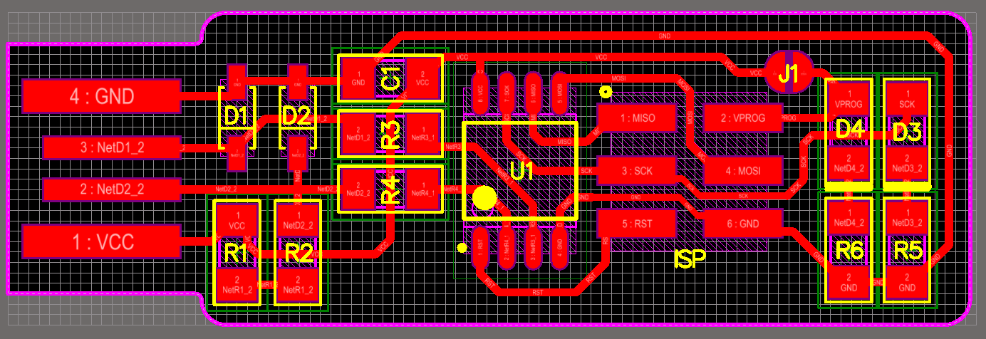
The image i use for traces and for cut are this:


Here the File
After I change the tip under the Machine with a tip of 1/64 inch; and set the speed, the offset distance; you can see in this image the parameters i use in a FabModules Choose load png from pc, select the file you want to crate, in my case .rlm (Roland Mill)it is similar to a gcode. and i choose the tool i want to use: 1/64 inch. On the right i can choose the machine i want to use, in my case the Roland Mdx-40; as default the speed is set on 4 mm/s, i reduce it to 3 mm/s. For this kind of circuit we need 2 or 3 offset, but you can set more offset for remove all the copper from plate, but it takes more times for the milling process. On the FabModules i set all the axes to zero because i set them manually on the machine.

this is the result of the milling:

Assembling and Soldering
For the first i take all the components I need and I catalogue it with a post it; in this way I can take easily every component during the assembling process.List of Material:
1x ATtiny45 or ATtiny852x 1kΩ resistors
2x 499Ω resistors
2x 49Ω resistors
2x 3.3v zener diodes
1x red LED
1x green LED
1x 100nF capacitor
1x 2x3 pin header

I need to see the position of every component on the pcb; for do that i see this scheme:

And this:

Attention Before solder all components you need to see the correct orientation of some components:
Zener Diode.
This component need to be polarized in the correct way, for do that you need to know where is the cathod of the component; in thic case the cathode is signed by a line on one side of the component surface
Led smd
All leds need to be polarized in the correct way, for do this also in this case i need to kwon where the cathode is. For this king of component, the symbol in under the component, and we can found different kind of symbol, in my case i have this Led:
If you can't see the symbol you can foun the cathod with a multimeter in this way. Select on the multimeter Diode Test:

And connect the two pins to the diode, if you don't see the light you must invert the pins. When the led in on, means that is polarized in the correct way, and the side where you connect the red pin is the cathode of the Led

At Tiny
For this Ic is easily to see the correct position; the pin 1 is marked with a dot laser-etched into the corner of the package
Resistors & Capacitors
All the Resistor and capacitor we use, don't need to be polarizedSoldering:
For the Soldering I use on the trace a flux paste:


THe first FabIsp i assembly, i have a problem with the led; because the led we have to te FabLAb are too small for this traces, and we can't use it on this board. I try to solder one of it, but for the second led (green led), i replaced it with a classic Led. like in this image:

My second FabIsp, i desolder some led from an old PCB, and i use it for my FABISP

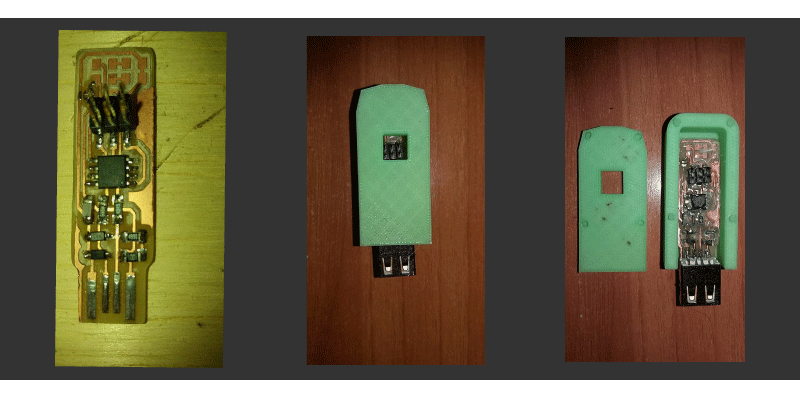
The result is this:

Program the FabIsp
For Program the FabIsp I can use Windows or Linux, but in all the tutorial I found about the FabIsp Programming, I see that all students have problems, so i decide to program it with Ubuntu. Fortunately we have a Pc with ubuntu in the FablAb Napoli, so i use it. If you don't have a PC with Ubuntu OS; you can install on windows a Virtual Machine, and use Ubuntu. You can download the Virtual Machine Here:After you choose Ubuntu as OS.
The follow Step after Install Ubuntu, Is to install all the software for program the FabIsp. I found all the Istruction of this Tutorial:
The software we need is called ToolChain and on Linux we install it with this command:
"sudo apt-get install avrdude gcc-avr avr-libc make" You can see that on linux we can Install software all togheter; you must insert a space in the command line between the name of the software you need to install. You can found instruction how to program the FabIsp with Windows on this
Tutorial:
After I have installed the Toolchain, i download all the drivers I need for program the FabIsp Here:
Before upload the firmware on the Attiny 45, we need to check on if the reset jumper is closed; It need to enable the At tiny 45 to receive files, and install the firmware. It's a Microcontroller with an EEPROM and a Flash memory(The difference is that can be reprogram more and more times) and we need to be able to write on flash memory. After I unzip it on the same folder, I enter inside the folder with cd command and the link of the folder where the drivers are. After do this, we run the "Make" command. This Command generate an Hex File called: fts_firmware.hex


After this steps, we need to upload the firmware in hex code on the FabISP with the programmer we use.(As Default we found a standard programmer of at tiny Family, you need to change this name with the programmer you're using) In my case we use this kind of Programmer: Atmelice. Using "atmelice" don't work, but using "atmelice_isp" It's all Ok.

After we do this, we need to connect the FabIsp in this Way near the programmer and the USB

After connect the FabISp like the previous image, you Run make flash. This will erase the target chip, and program its flash memory with the contents of the .hex file you built before you run "make flash" this erase the chip, and program its flash memory with the contents of the .hex file I built before. Now the firmware we build before is on the chip; but we need also to address the chip register. You can do this with the "make fuses" command.
Test The FabIsp
After make fuses command, we need to test if our FabIsp Work; disconnect the FabIsp from the programmer, and connect it with Usb. When It's connect to the Pc, we can see all the connected device with the "lsusb" command; and Linux show the FabIsp as "Multiple Vendors USBtiny". It means that it's all ok. The last step is to disable the FabIsp to be a programmer that can program other boards, and to disable the chip from other programming. The first spep is with a command line: "make rstdsbl" this command disable the chip reset. The second operation is to open the jumper we make when we assembly the FabISP.

