Electronic Design

Assignment:
Redraw the echo hello-world board, add (at least) a button and LED (with current-limiting resistor) check the design rules, make it, and test it extra credit: simulate its operation extra credit: measure its operation
Work:
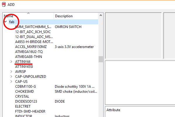
I start this assignment from the design of the original hello board: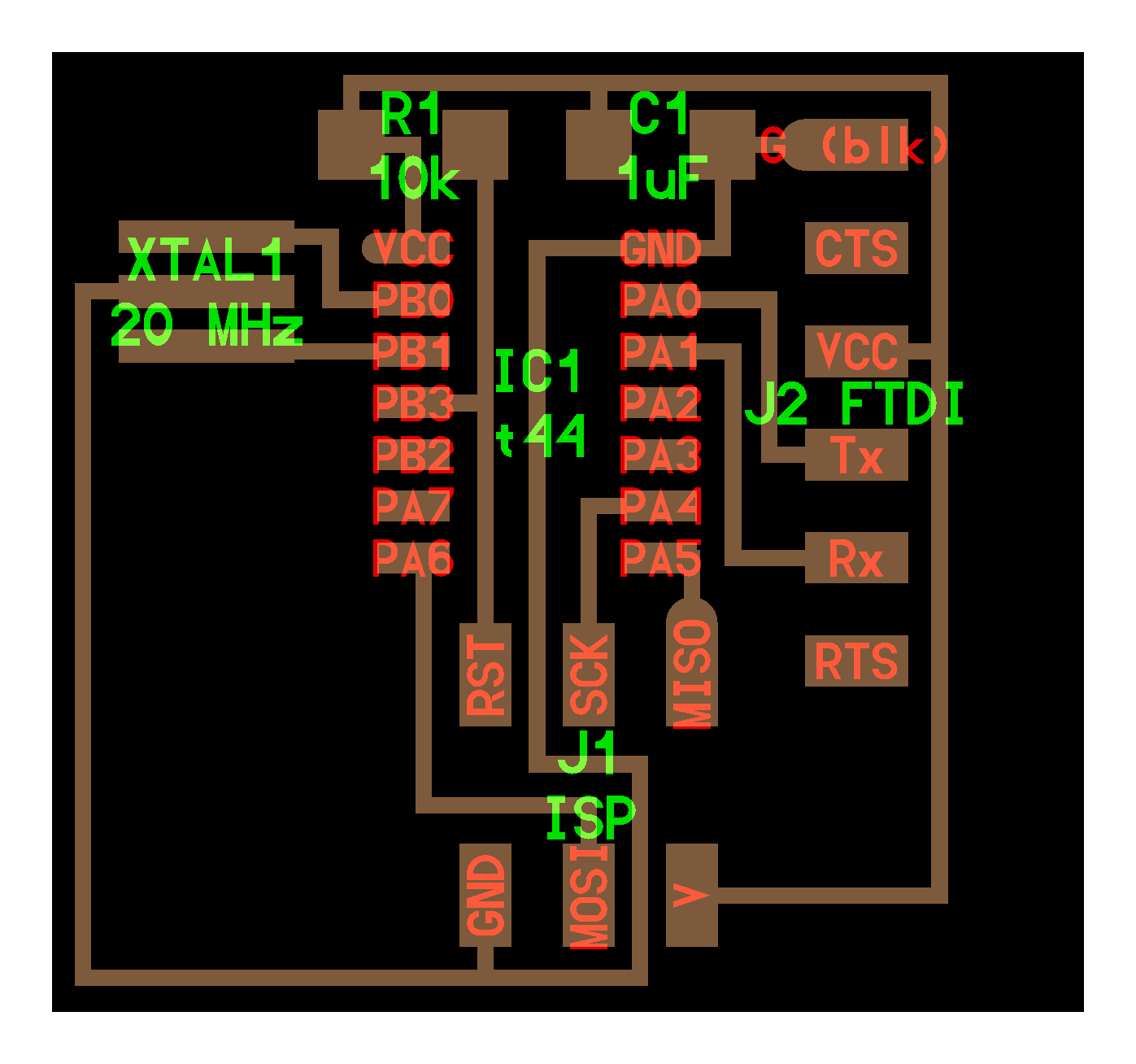 I Install Eagle from this Link
and i follow this Tutorial and i search information about the component I need
expecially the resistor for the led. It's possible to calculate the resistor we need on this website:
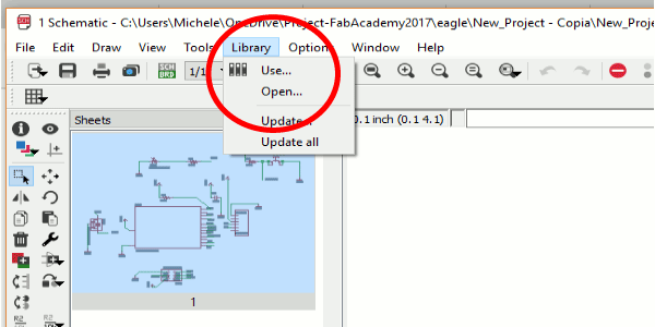 After do this I have all the component i need in Eagle.
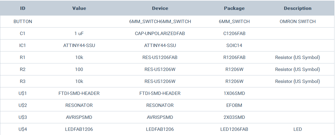
 this is the list of the component :
Attiny 44
For undertand how use better the Attiny 44 I read the datasheet for undertand the Pins and his internal architecture: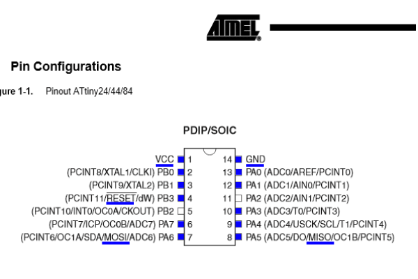 SCK(Serial Clock): Programming clock, generated by the In-System Programmer (Master)
MOSI(Master Out - Slave In ): Communication line from In-System Programmer (Master) to target AVR being programmed (Slave )
MISO( Master In - Slave Out ): Communication line from target AVR (Slave) to In- System Programmer (Master)
RST(Reset): To enable In-System Programming, the target AVR Reset must be active. To simplify this, the In-System Programmer should control AVR Reset
GND(Ground): Common Ground


In my case I use Port B for connect the chrystal resonator so the attiny can work at 20 Mz and I use port A for connect the led and the button. This information show the voltage, the temperature and the current of the chip
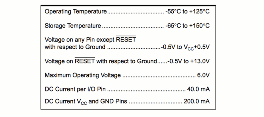
With this information we can calculate the value of the protection resistor for the led. You can use this Website
- So i have this information:
- Source Voltage:5V;
- Diode Forward Voltage:2,2V;
- Diode Forward Current:20 mA
The Pull Up resistor
The pull up resistor is a resistor connected between a signal conductor and a positive power supply voltage to ensure that the signal will be a valid logic level if external devices are disconnected or high-impedance is introduced.This kind of connection is used for bus connection, and logic device,
The pull up resistor will ensure that the pin is in either a high or low state. More information Here
The Schematic

For add e move the component:
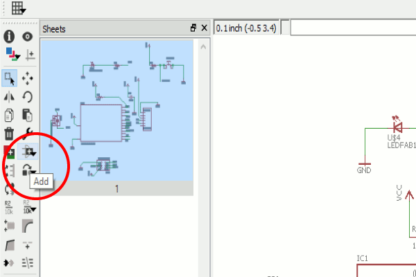
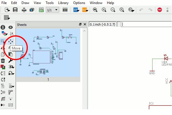
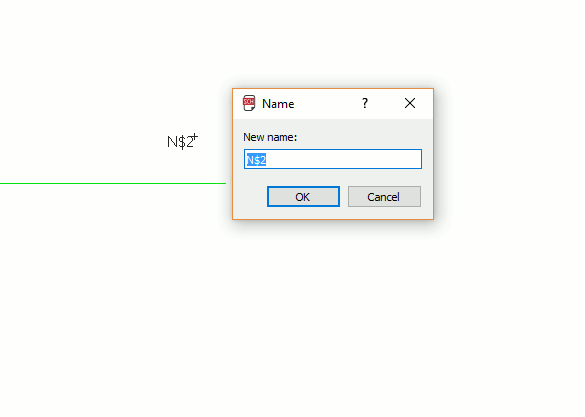
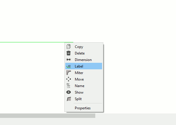
for connect the component I use the label function. and I connect to the component i want using the name funcion. After do this i swith from schematic to board and I move the component where i want
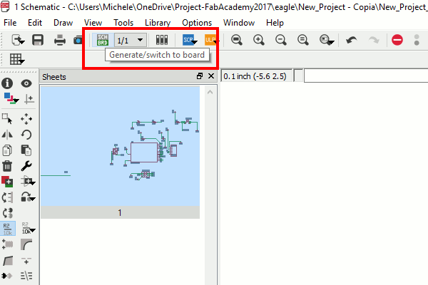
After move the component I set the Design rules for my trace width and distance:
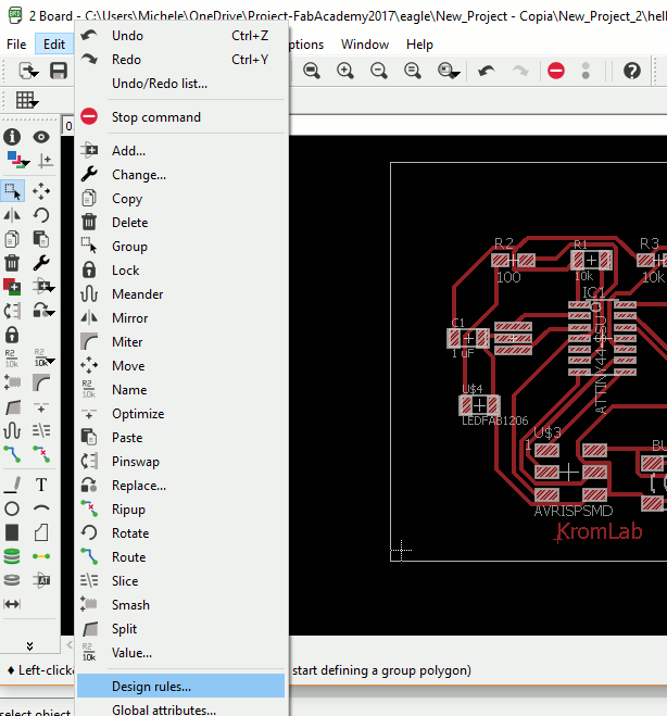
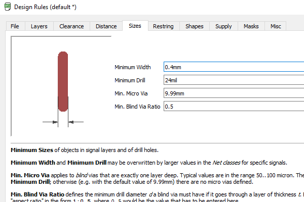
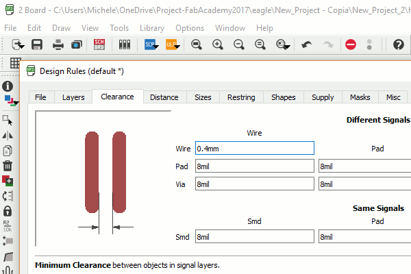
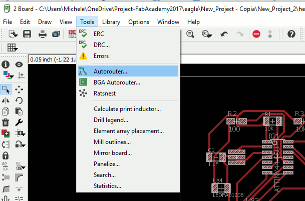
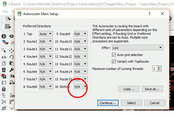
I set them to 0,4mm; and i choose to autorute the trace. Important: choose to autorute only the top of the board.
After do this I export the trace and the cut line as two different image that i this is the design of my hello board:


After I export the png image of the traces and the cut of the board, I use Fabmodules for generate the file .rlm to use with the Roland Mdx 40. When I cut the PCB I understand that I made an error:
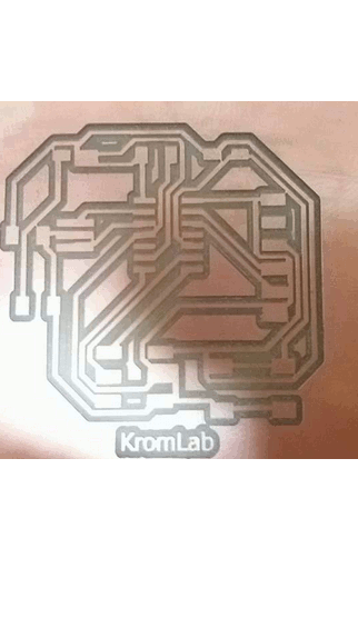
When I set the design rules i don't set the distance between the via and the pad and it's too small, so i set it to 0,4 mm and I regenerate the trace with Eagle, and I export them:
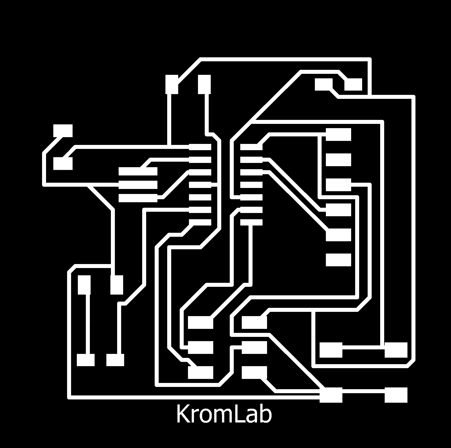

. And I use the FabModules for generate the .rlm file of the board:
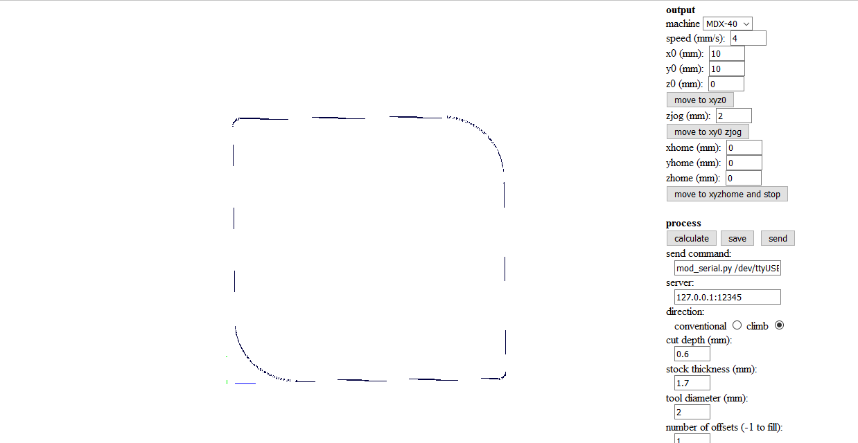
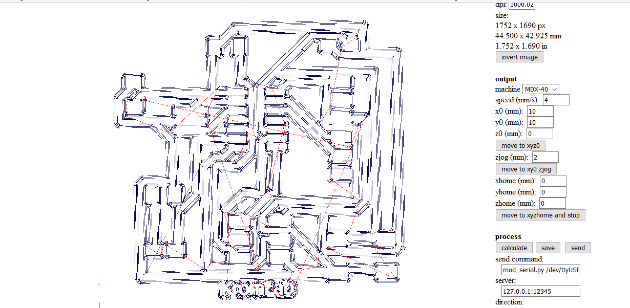
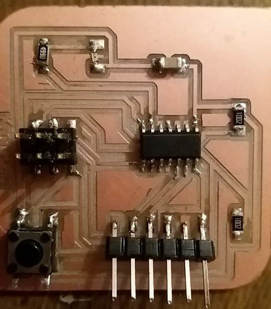
This is the good helloboard I made.
Program the AtTiny 44
For Program the Attiny 44 I use the Arduino Ide, and i set on it some important information:First I install the Attiny microcontroller support: Insert the follow link on the setting of the Arduino Ide like in this picture:
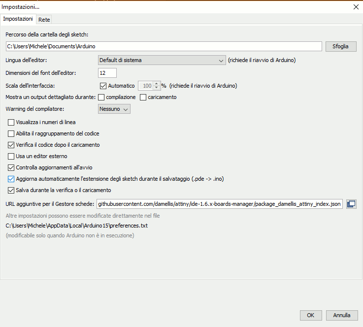
You can download the file here: "https://raw.githubusercontent.com/damellis/attiny/ide-1.6.x-boards-manager/package_damellis_attiny_index.json"
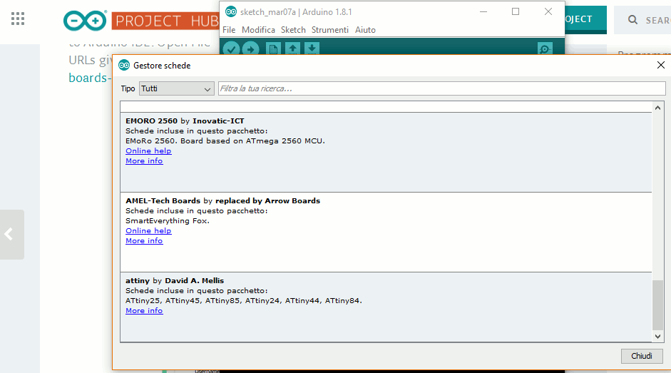
Now we have the Attiny as chip to program

Here a video of my board in function
Download ZONE
- Back To: Home
- Date: 1st March
- Topic: Electronic Design
