
Electronics Design.
For the assignment of the 5th week, it will be divided into 4 differentiated parts: Create an ISP, CAM, Programing the ISP and a group assignment.
ISP
The FabISP is an in-system programmer for AVR microcontrollers, designed for production within a FabLab. It allows you to program the microcontrollers on other boards you make. In my case, I based on the design made by David Mellis to create my design. I chose this design because it was one of the tutorials that were well explained and detailed with the manufacture of the board. Also, the soldering are easier because it is not so small and has a USB connector.Schematic
I did not want to just download the board, but to make design modifications and adapt it to the existing materials in the laboratory.David's design contemplates a 12MHZ crystal and in parallel two 18uF capacitors. In addition to other 2 capacitors of 10uF and 0.1uF in parallel to the power that makes filter. In the following picture you can see David's design.
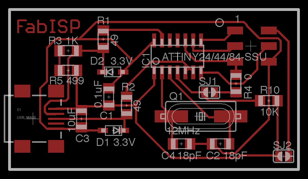 In our laboratory we have another OSC, one of 20MHZ that already incorporate the built-in 18uF capacitors, in addition to the capacitor that uses a filter is only one of 1uF, according to the technical specifications of the Atiny44 will not hinder its operation.
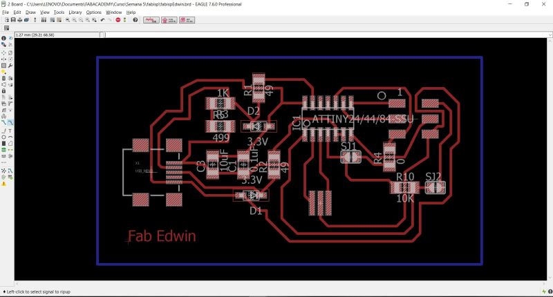
Using the software Eagle of autodesk and with the libraries of the Fabacademy, I realized my design that can be appreciated in the image.
In our laboratory we have another OSC, one of 20MHZ that already incorporate the built-in 18uF capacitors, in addition to the capacitor that uses a filter is only one of 1uF, according to the technical specifications of the Atiny44 will not hinder its operation.
Using the software Eagle of autodesk and with the libraries of the Fabacademy, I realized my design that can be appreciated in the image.
 To proceed with the manufacture of the board, we must export our design in an PNG format, eliminating the unnecessary elements to be able to carry out the work.
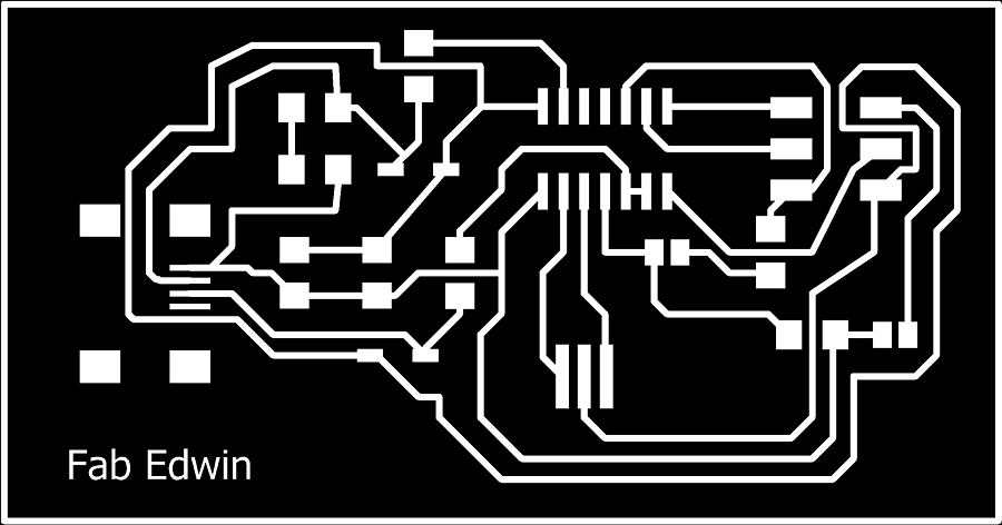
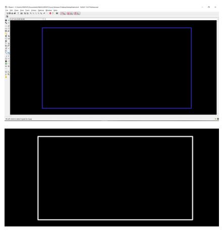
 The result of the exported image is the following picture
Now I export the bottom layer, which will be the file out traces to be able to cut the board
CAM and Fabrication
For the CAM process; fabrication, we must perform several steps that will be explained below.Modules
With the image of our board, we enter the fab modules to generate the code G, since it is the code that the CNC machine interprets. We select our image (png format) as input format, g-code as output format and for process PCB traces (1/64), in this way we generate our board.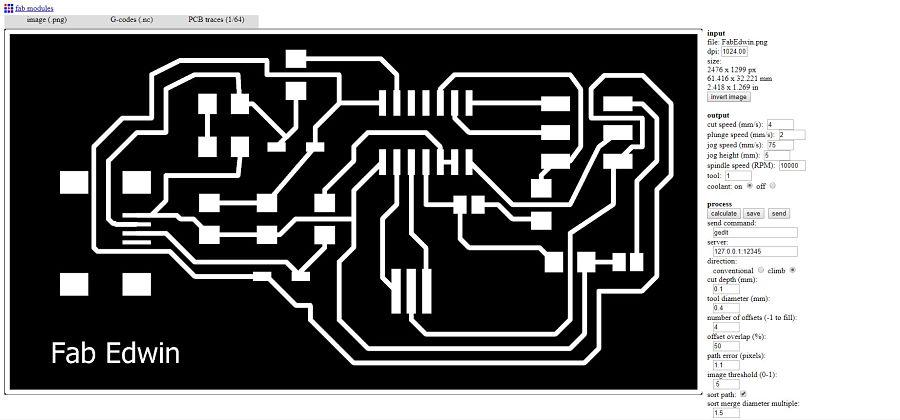
Parameters
The parameters used in the fab module, after several test in the lab, are the following:| Output | Process |
|---|---|
| Cut speed (mm/s) : 4 | direction: climb |
| Plunge speed (mms) : 2 | cut depth(mm): 0.1 |
| Jog speed (mm/s): 75 | tool diameter(mm): 0.1 |
| Jog height(mm): 5 | numbre of offsets (-1 to fill): 12 |
| Spindle speed (rpm): 8000 | |
| Tool: 1 | |
| Coolant: off |
CNC Machine
The machine we use to manufacture PCBs is a Roland MDX540, which is a CNC machine as shown in the picture.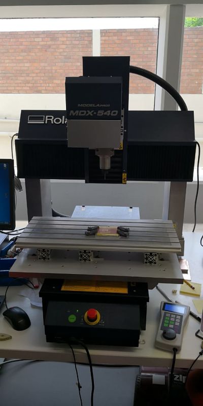
Tool
The tool used is a conical endmill at an angle of 45º, as seen in the picture.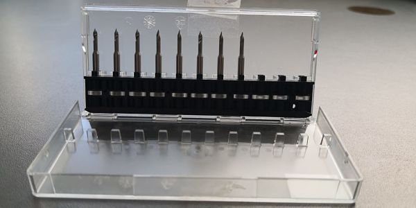
G Code
The fab modules gives us as a result a g code that is interpreted by the CNC machine, this alpha numeric code represents the path and cut that the board makes. Visually it will perform a job as shown in the picture.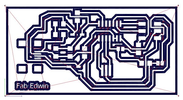
Change tool
Once the g code has been obtained, we must make the tool change for the one selected.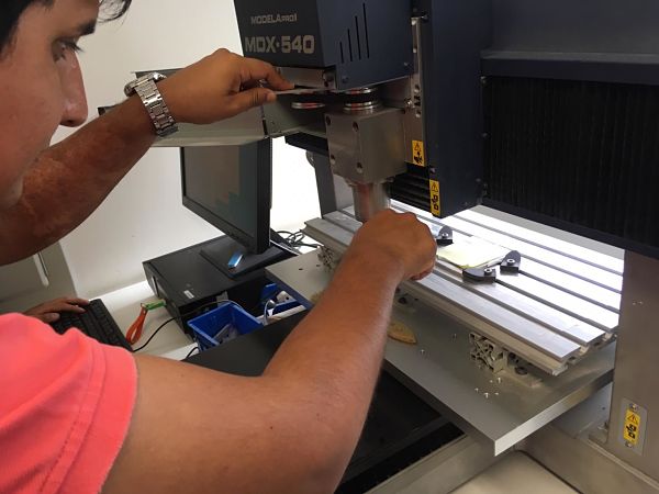
Zero position
We must position the zero position of our board, for this we use the manual controller. Once we have positioned the zero point on the x-axis and y-axis, we press origin. Only in the case of the Z axis do we use a special sensor to locate the zero position on z-axis.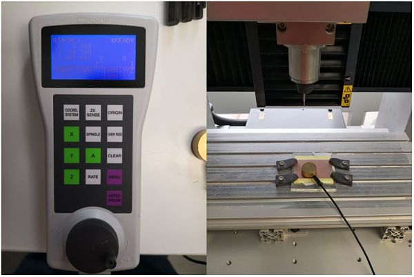
Milling
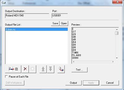
We use the software of the Roland: MDX-540 [NC-CODE] using the speed of 8000RPM, the positions of the x-axis, and, and z are the coordinates of the tool.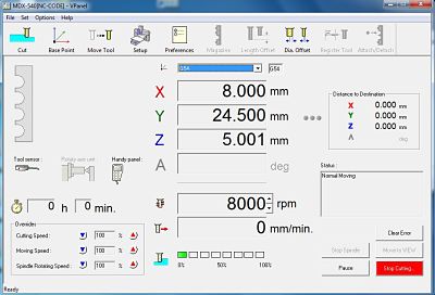
The Cut option is chosen, and we drag our file generated by the Fab Modules, click on apply and finally OUTPUT.
We can see a small video of the ISP cutting process.
Soldering the board
The soldering process used for my plate is with soldering paste, the material for the PCB is CEM3. With the help of a soldering station and some special tools, we proceed to incorporate the components, taking extreme care to damage the PCB or materials. In the image I am soldering another PCB, becuase I like to have an additional ISP in case I have problems with the first one.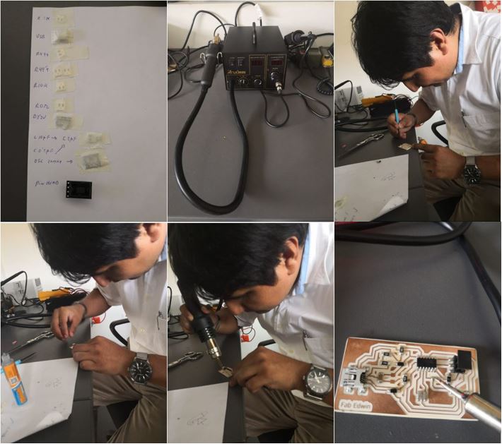
Programming the ATtiny44
For the programming of the ISP, a computer with Ubuntu was used. We used a tutorial that can be seen in this link. The necessary software was installed using the following commands:sudo apt-get install flex byacc bison gcc libusb-dev avrdude
sudo apt-get install gcc-avr
sudo apt-get install avr-libc
sudo apt-get install libc6-devwget http://fab.cba.mit.edu/classes/863.16/doc/tutorials/fabisp_programming/fabISP_0.8.2_firmware.zip
unzip fabISP_0.8.2_firmware.zip 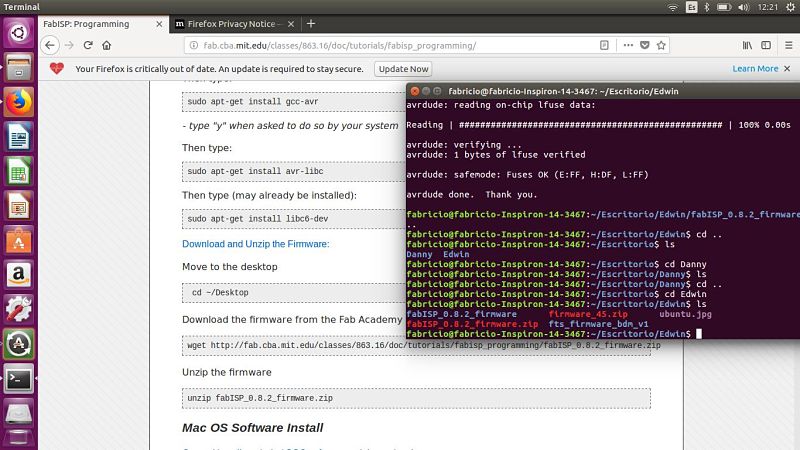
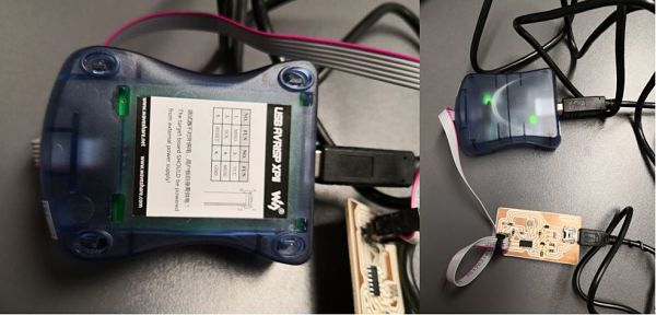
The next step is to connect my ISP to the computer with the help of another ISP programmer, in this case I used the USB AVARIPS XPII.
Once connected and seeing that everything is correct, we use the following commands.
make clean
make hex
make fuse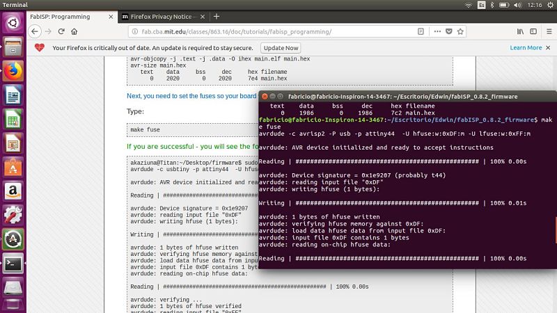
We write the last line of code
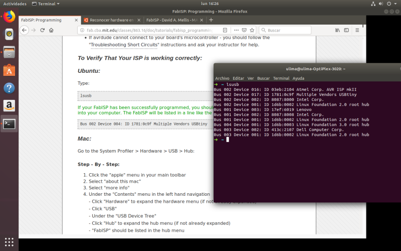
make program and we have our ISP ready!.In this picture, my computer recognize my ISP.
Hero shot
And this is my ISP.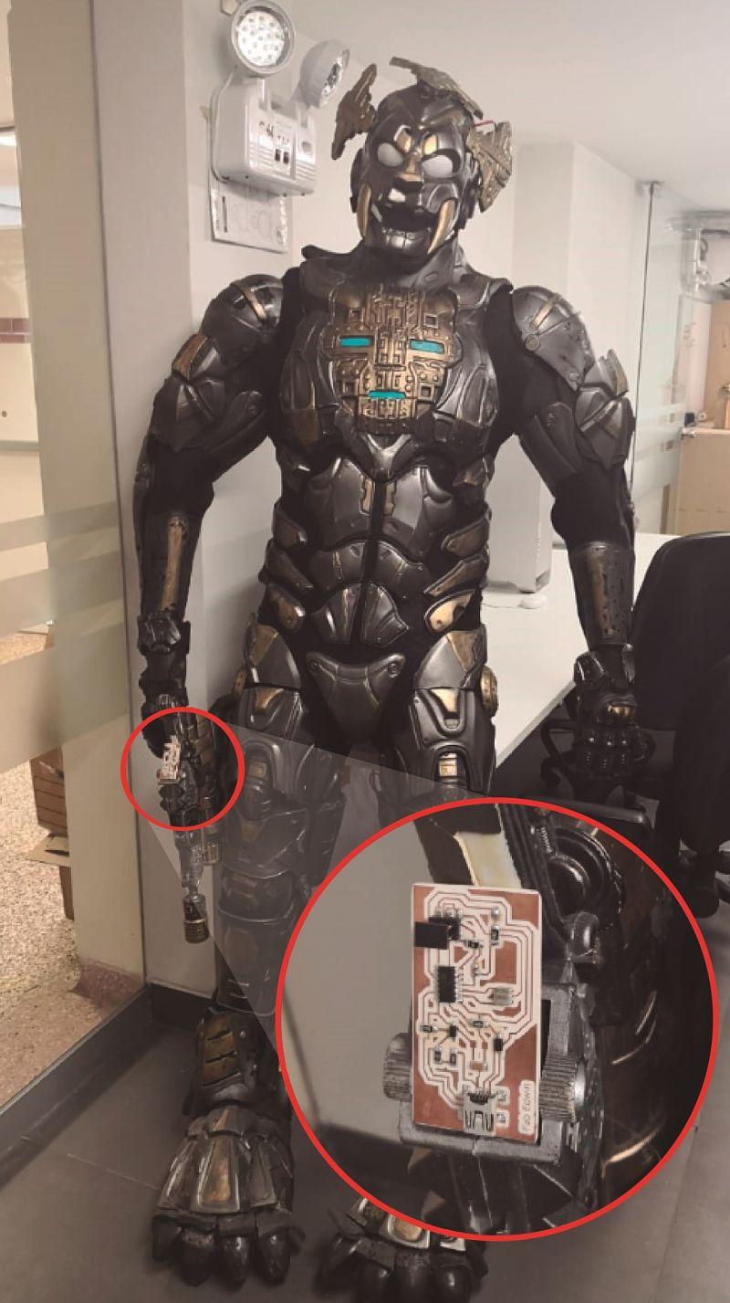
Group assignment
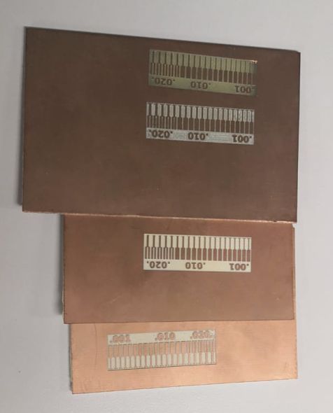
For the group work, as a personal contribution I made the machining of the line test with two types of materials and two types of milling cutters. The materials were a ceramic PCB and a fiberglass one. The milling machines were a 1/64 and the conical endmill.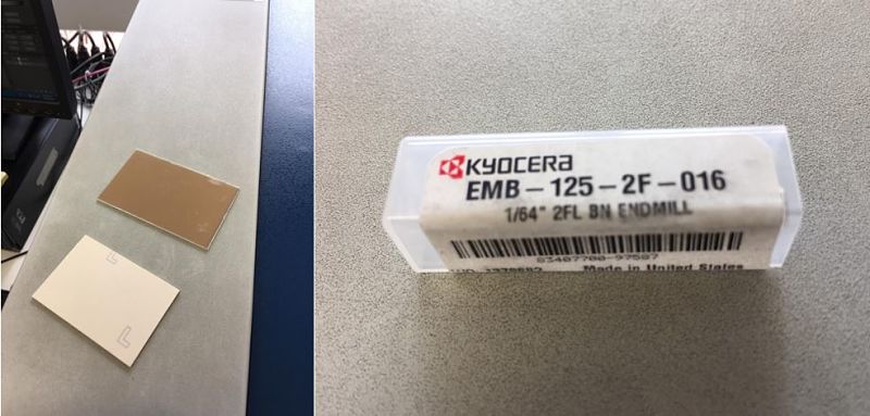
The result of the cuts can be seen in the image.
Yoy can read more in the web of our laboratory: CIT
Download files
You can download this files Here:Schematic.
Board.
PNG Board.
PNG Out traces.