14. Networking and Communications
This week we returned from our break and got back to work. The break was nice, but I’m glad to be getting back to class to learn more and keep working on my final project.
Our individual assignment this week was to design, build, and connect wired or wireless nodes with network or bus addresses, and our group assignment was to send a message between two projects.
Group Assignment
The group assignment this week was to send a message between two projects from different students. To do this, we used Katie’s satshakit and force sensor to send the force value over to Kai’s LCD board. The message being sent doesn’t fit perfectly on the screen, but you can see that the resistance value in the lower left corner changes nonetheless whenever we pushed down on the force sensor.
Individual Assignment
I’ve had no experience with networking at all up until this point, so for the individual assignment this week, I wanted to start out simple and work my way up from there. I began by working with a wired connection of master and slave boards using a serial bus to connect all three under the R-232 serial data standard.
R-232 Boards Production
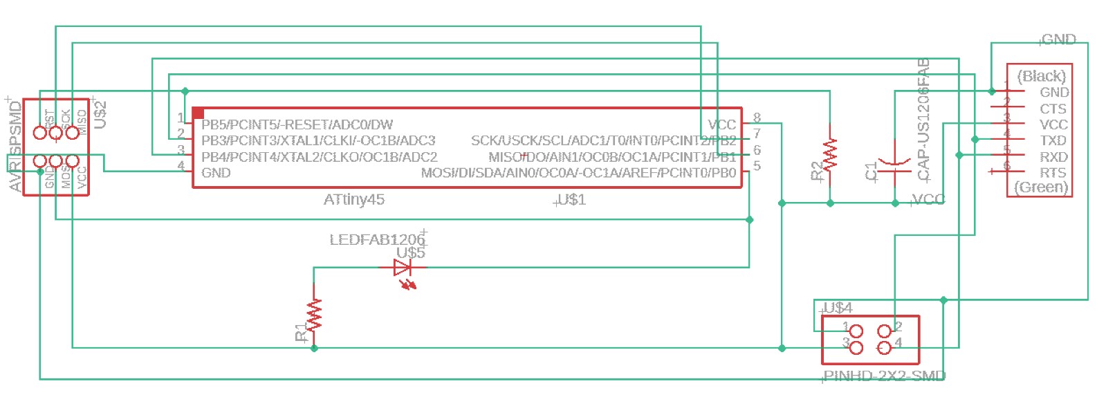
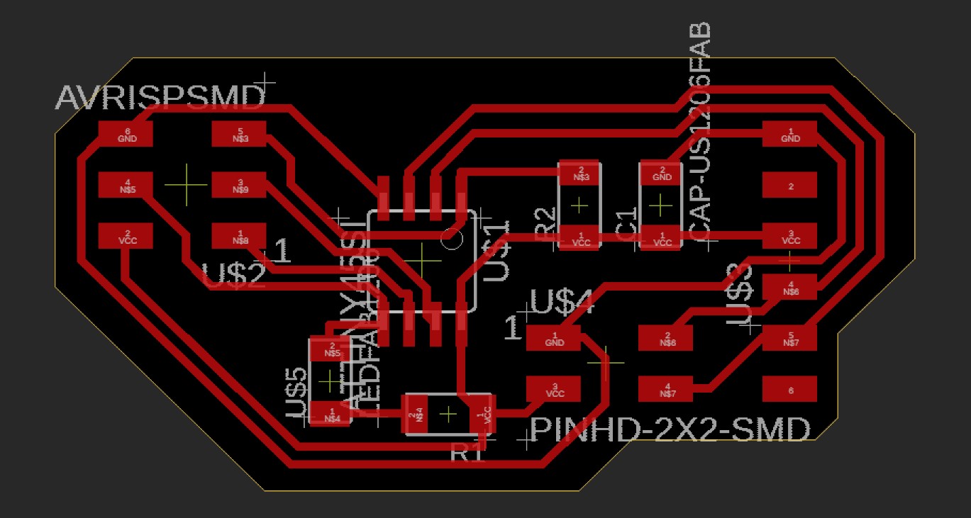
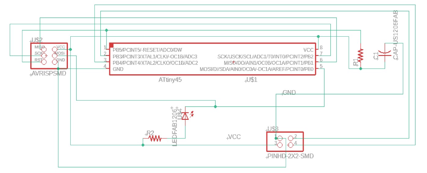
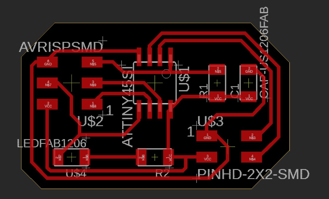
I started my work again with schematics and board layouts for the master and slave boards in eagle. I used the board layout that Neil provided as a reference, but I ended up changing the path of the VCC line to what I found to be a more efficient route.
Here’s the master board layout that Neil used, and you’ll notice that the VCC line takes a longer route to reach all the way to the tiny 45 chip.
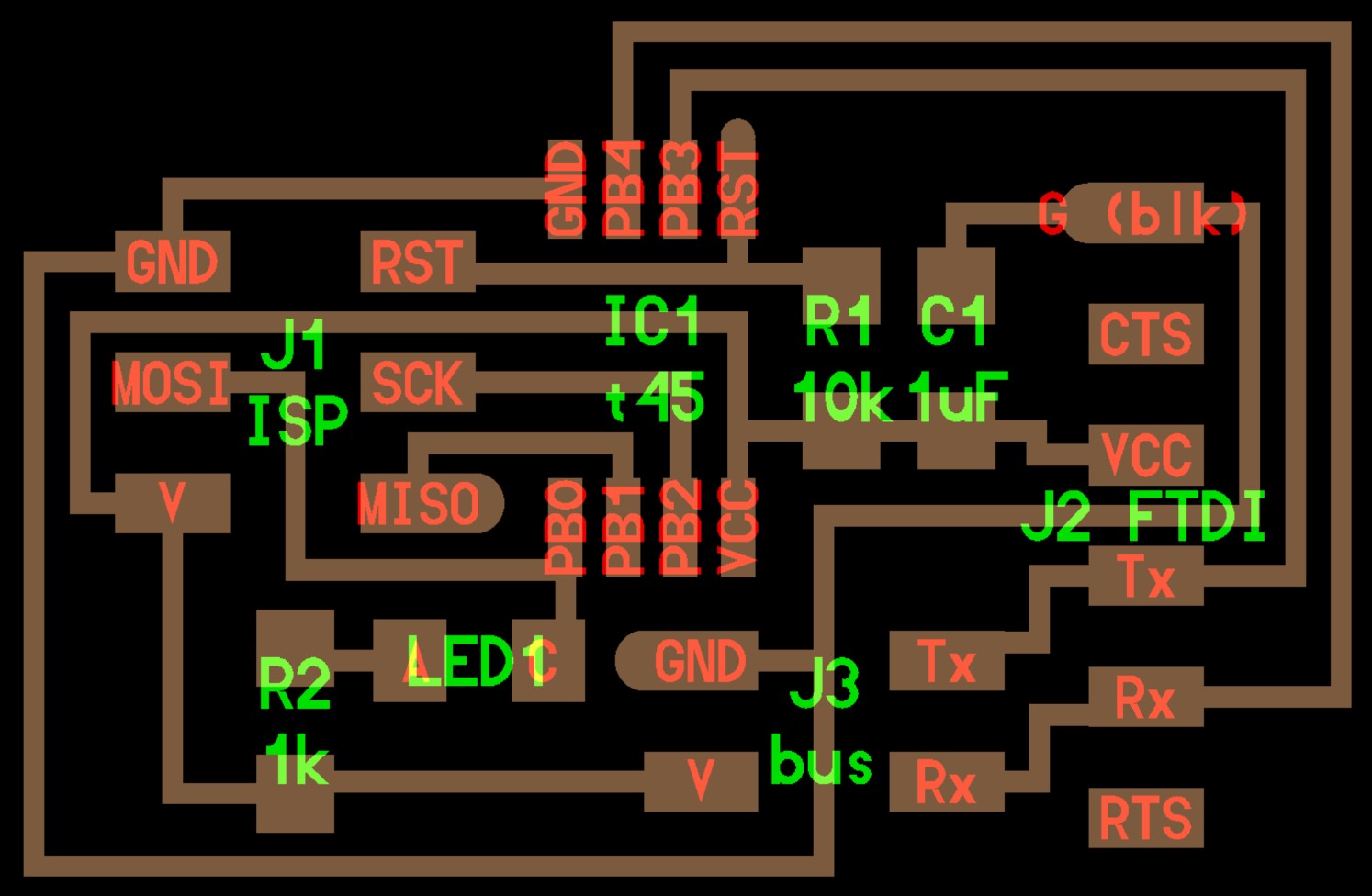
I was able to shorten this a little bit by rearranging the LED and its resistor, leaving an opening for the VCC route to go through.
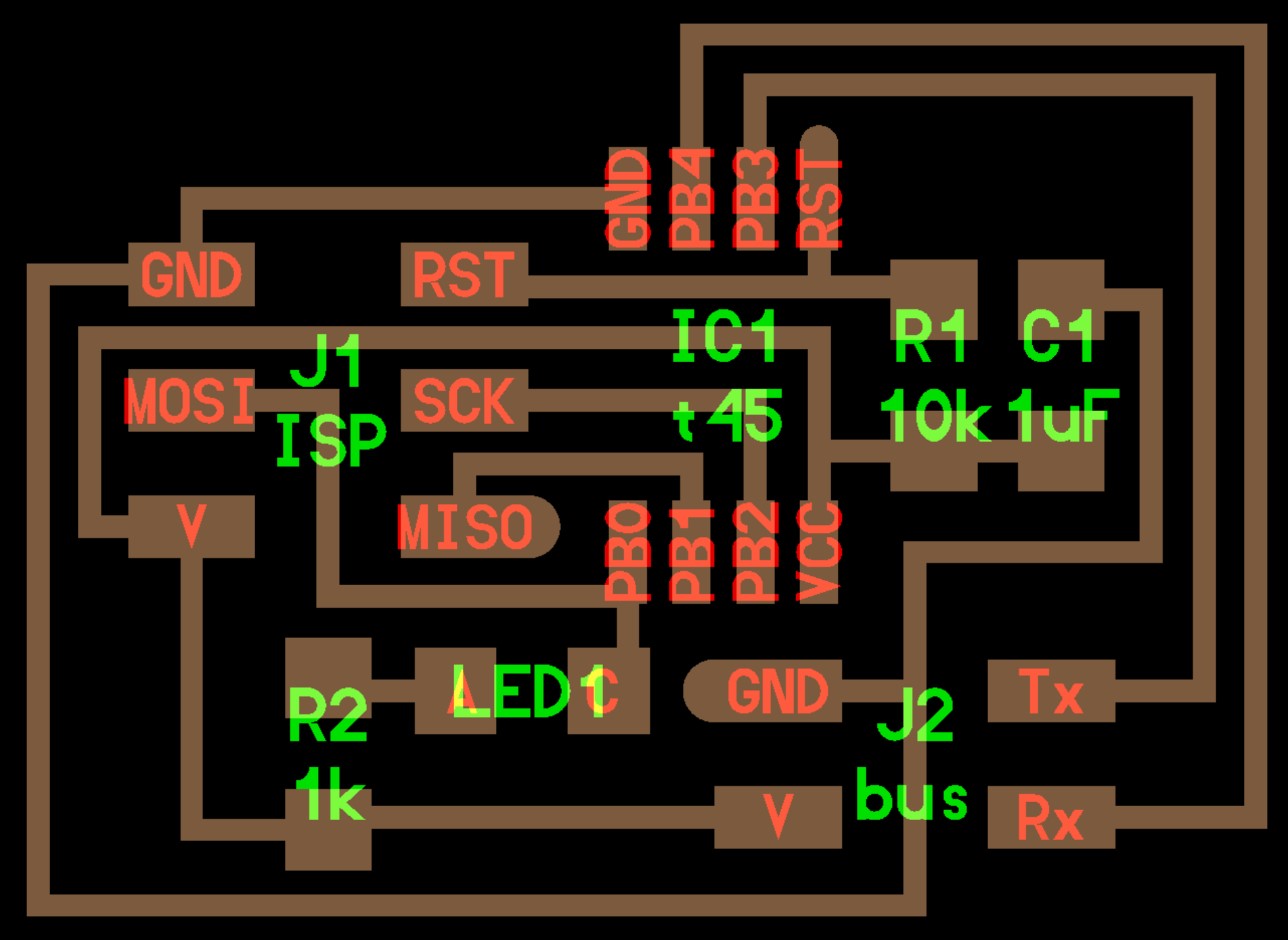
Now here’s the slave board layout he used. Notice that this one does not have an FTDI connection for normal serial communications, but rather it has the single four pin header that sources VCC/GND for power and ground, as well as Tx and Rx for serial communications along the ribbon cable serial bus.
Here’s the board I made, you’ll notice that I used the same path for my VCC line again.
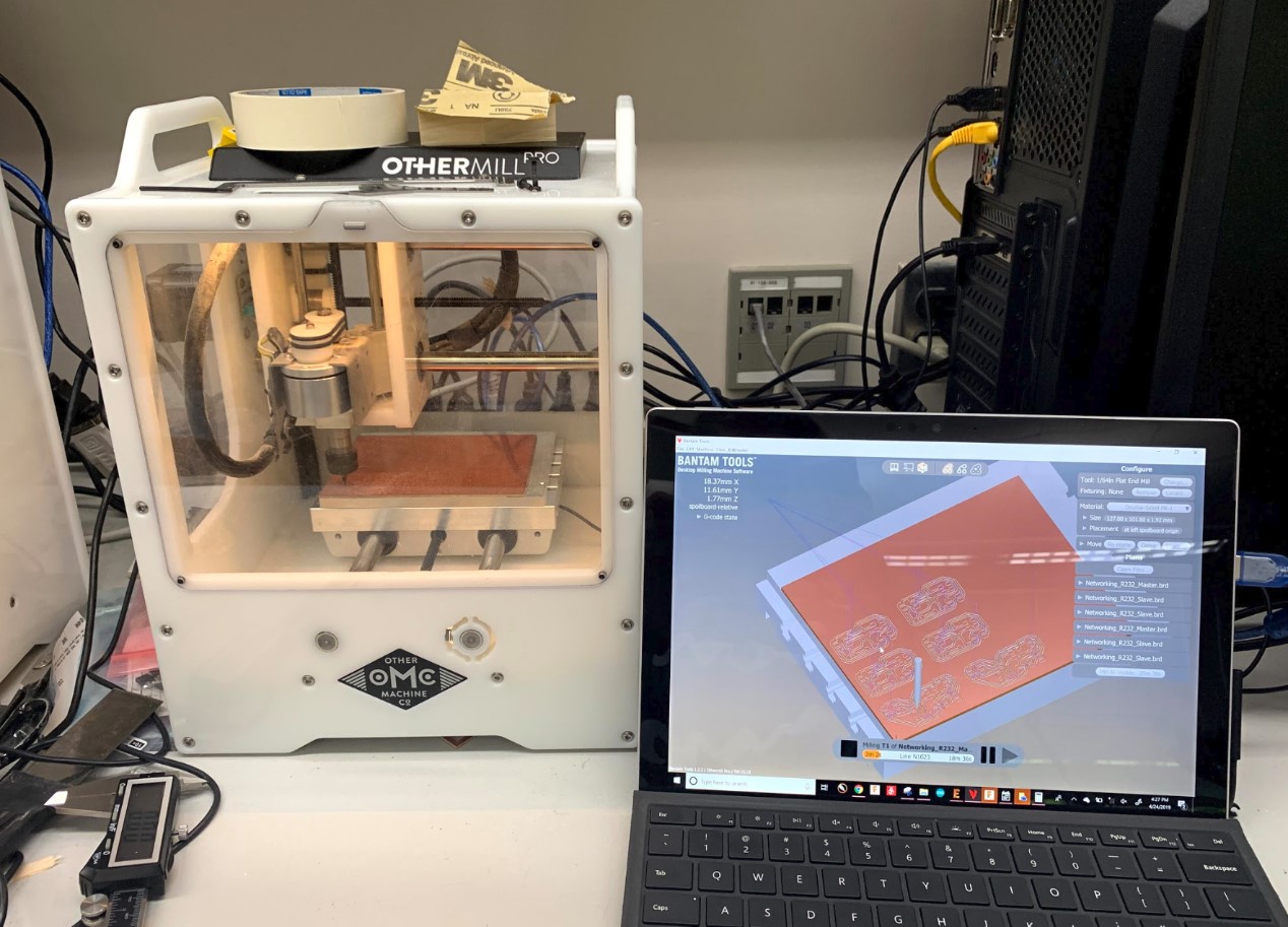
Milling
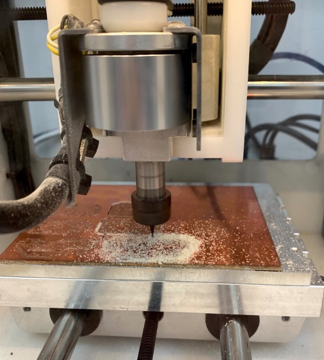
Once I had the boards designed, I went on and cut them out on the Milling machine.
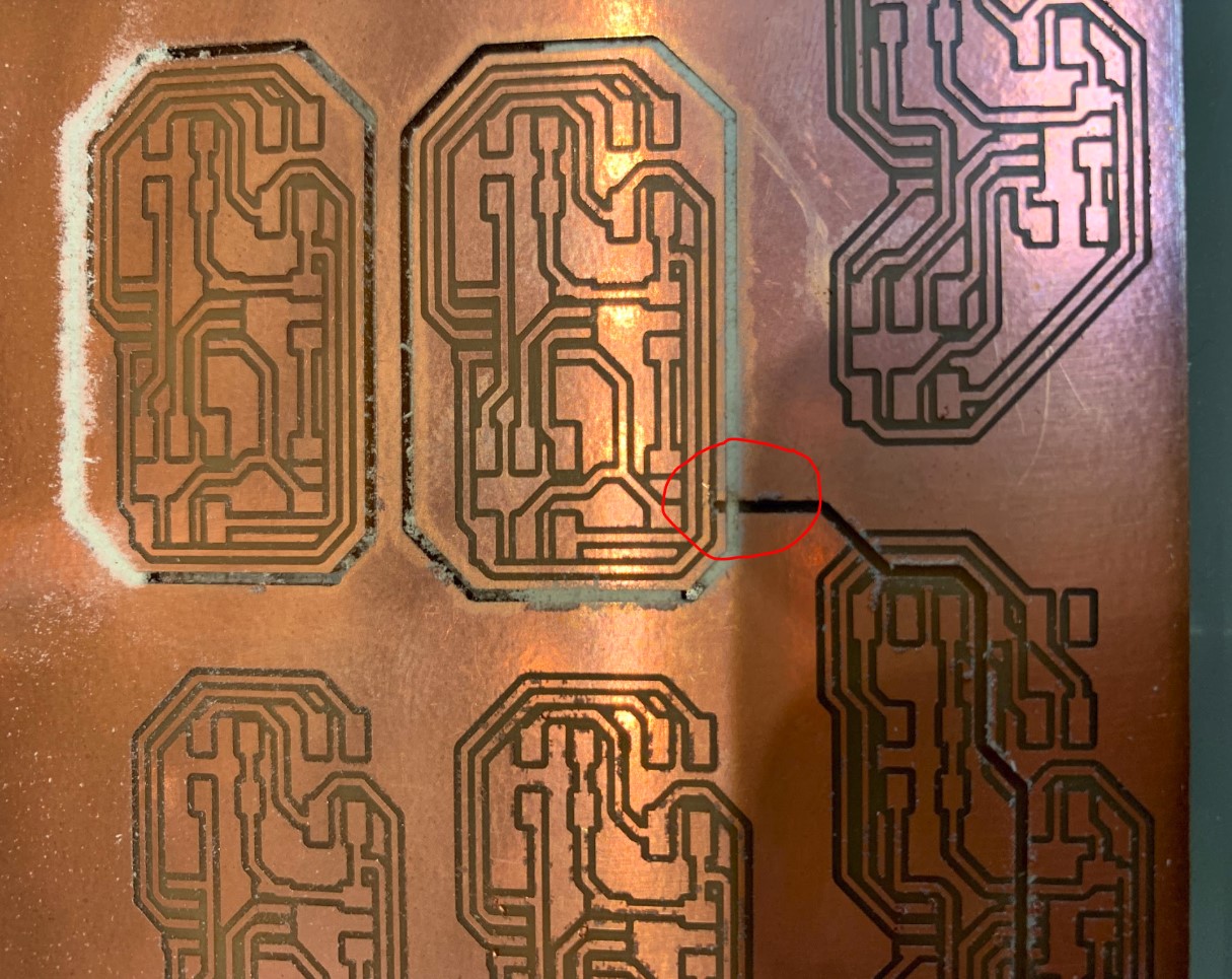
Things were all going well, at least until I started doing the outline cuts. The first two outlines went well, but when it ran back down to do the third outline for my Master board, it started the outline cut right in the middle of the board. I had checked the placement of it, I had looked at basically everything really to be sure that this wouldn’t happen, but somehow it still did. I think the issue is that it got itself out of alignment in the process of doing the other cuts, so when the router came back around it thought it was in the right spot, but it wasn’t.
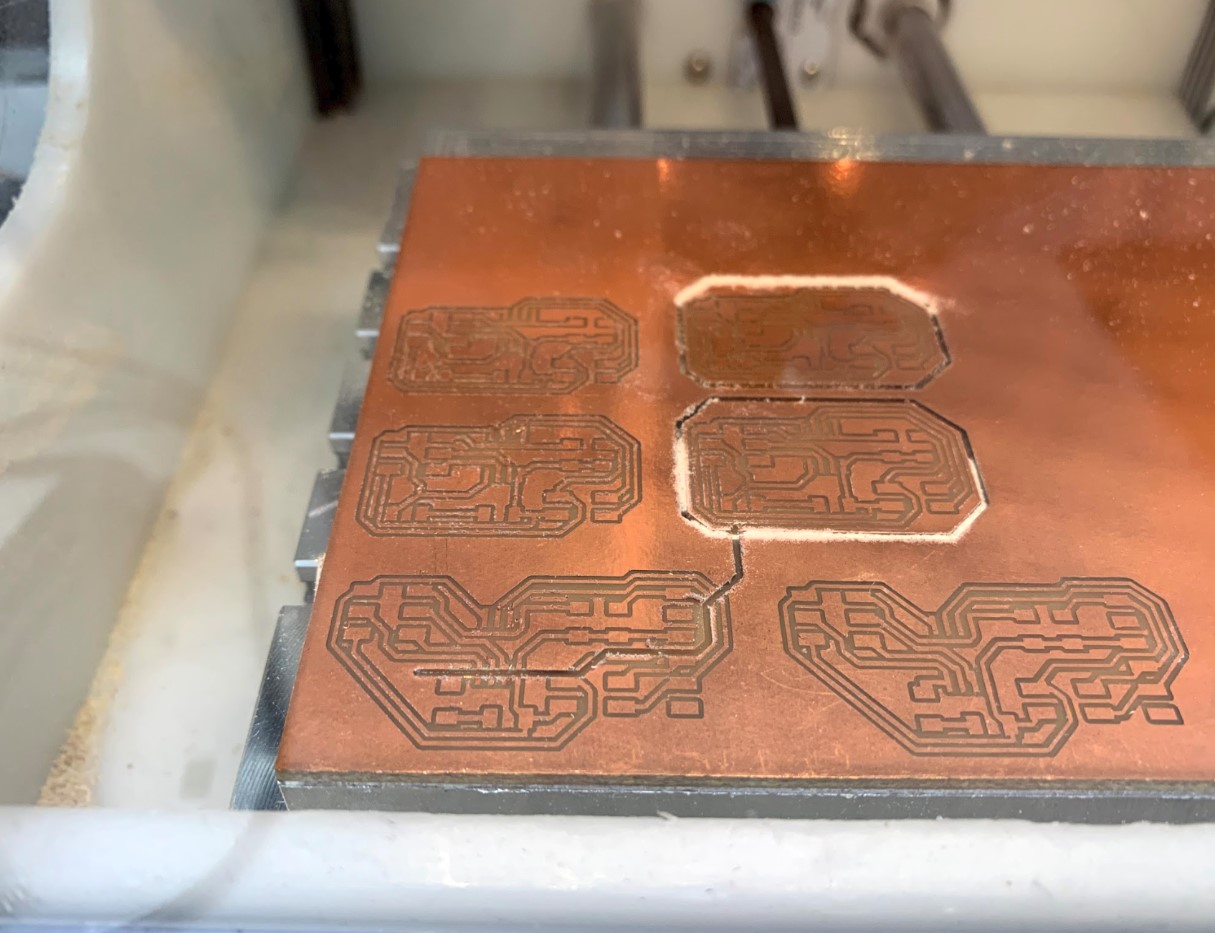
Luckily, the only board that got destroyed was the one that was cut into initially. I managed to stop it just in time from hitting another boards traces, as you can see below.
I think that the issue was the alignment because then I tried running another outline cut again right after that, I watched it do almost the exact same thing. Luckily, though, I was able to stop it in time and keep it from ruining another board. This was when it hit me that the machine was probably out of alignment, so I homed all of the axes and tried it again. This time, the other cuts all ran just fine.
Soldering
Next I got to work on soldering again. I really enjoy soldering, especially when I’m working on new boards, so needless to say I had fun with this.
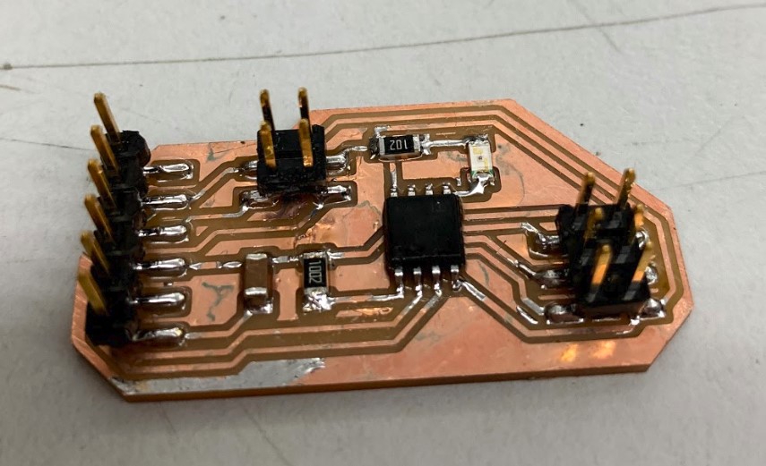
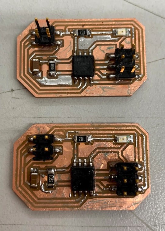
It took a while to get all three boards made, but once I was done I was proud of how they all looked.
Here’s my master board.
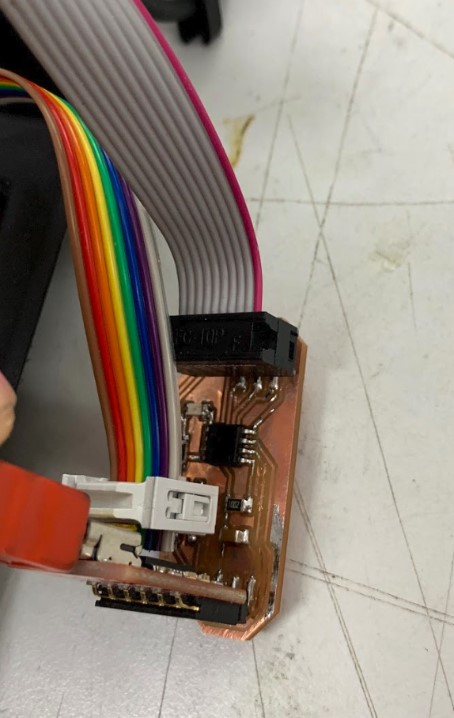
And here’s the two nodes to go with it.
Making the Serial Bus Cable
Next I had to have some way to connect all of the boards. Since we didn’t have any ribbon cables in the lab with three headers, I went ahead and made one. Mr. Taylor showed me the basics of it, and I had it down pretty soon after that.
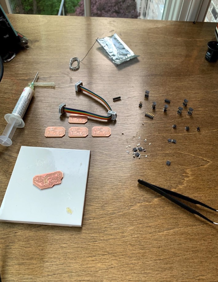
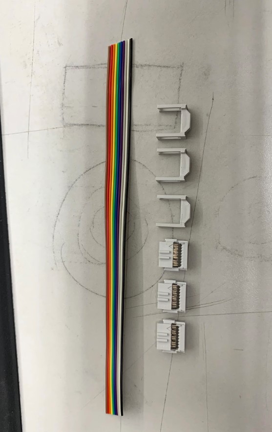
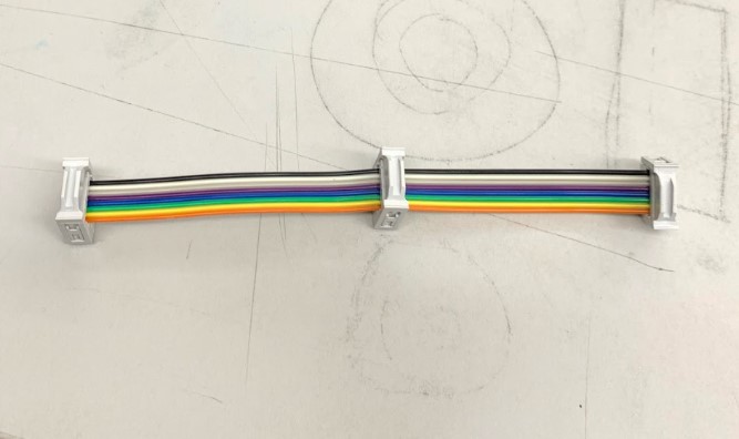
It all starts with the cable itself, as well as the headers and the header caps to go with it.
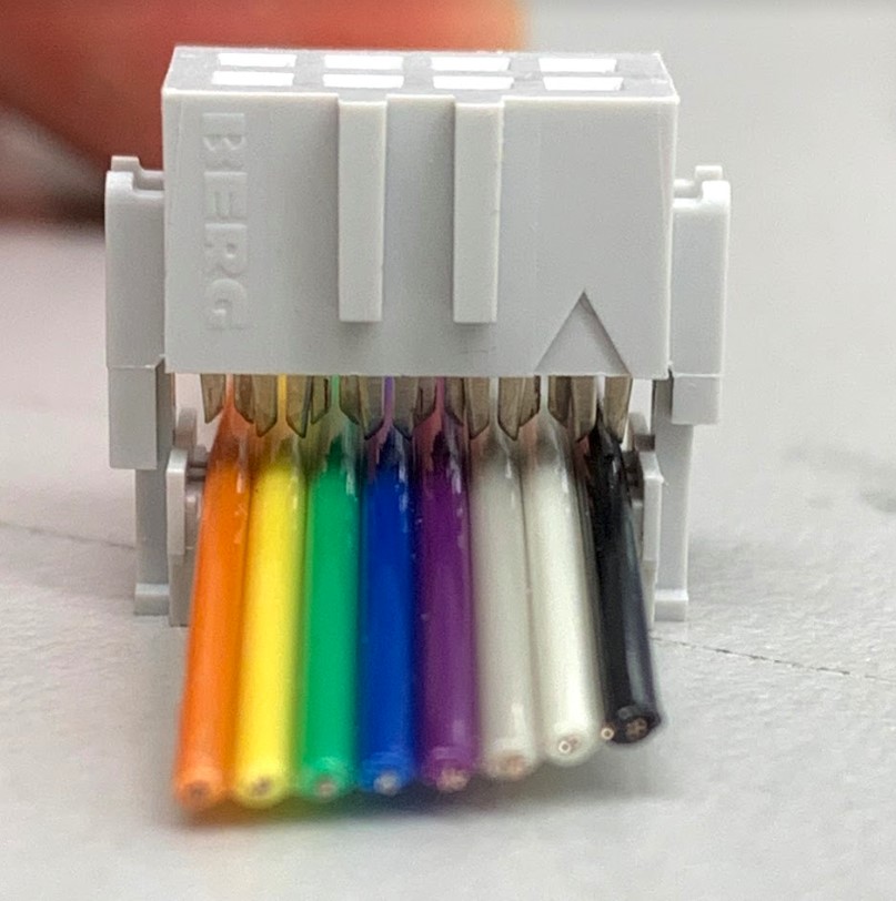
First I had to feed the cable through one end of the header like shown. Notice how the teeth all line up perfectly with the individual wires below them.
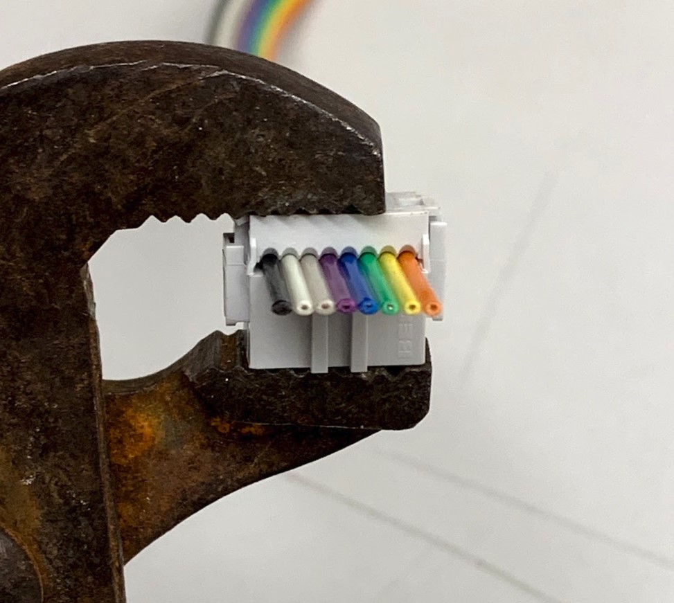
Then I used pliers to squeeze the header down into the cable securely, making a nice snug fit.
Then I just did the same thing two more times for the other headers.
Programing
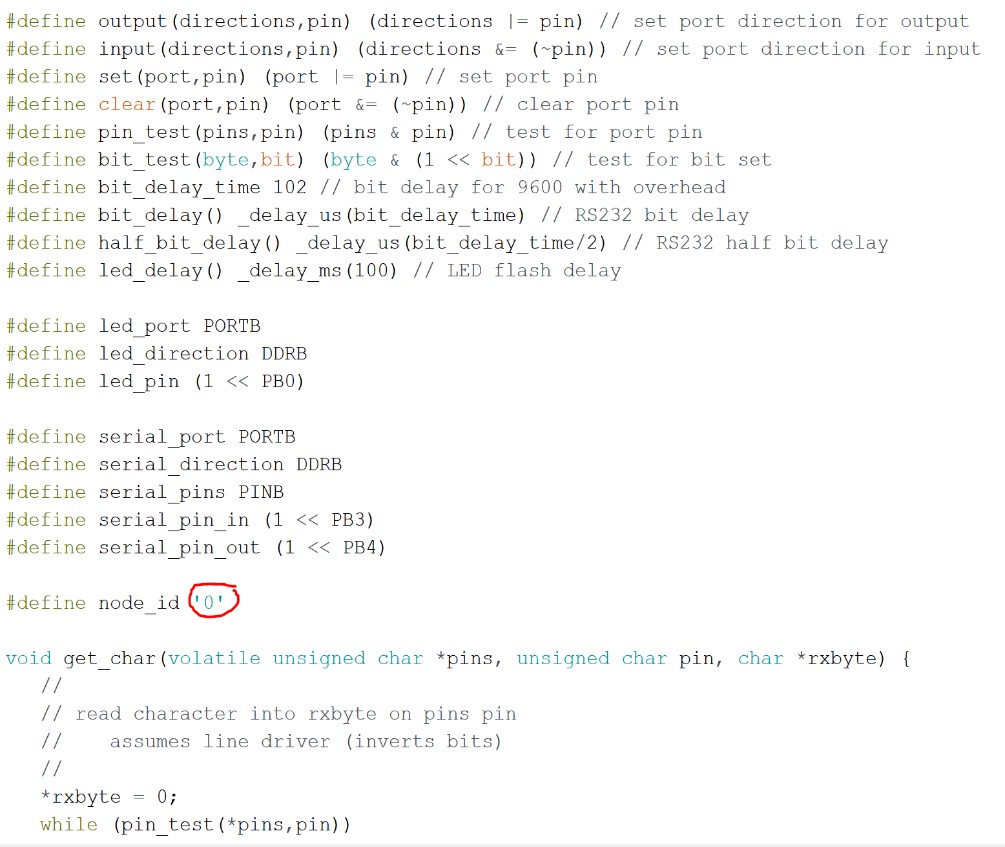
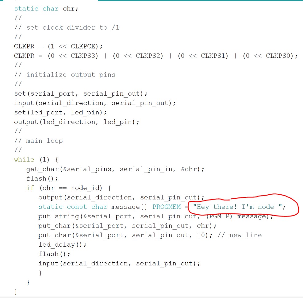
Next came the fun part, programing each of the boards. I began by getting the C code from the lecture notes, then I pasted it in Arduino to see what I could find. Once again I felt like I was in over my head with all of the code, but after some time I started to understand differrent parts of it all.
The main thing I had to focus on for each board was the individual nodes ID. Each node has an ID, a number ranging from 0-2 based on which of the three boards is being named. The master board is node zero, the first slave board is node 1, and so on. I changed the node values in the code for each board, then I also adjusted the messages that they would all send to give them their own identities.
Once I had each different version of the code ready, I hooked up the boards to my programer and tried uploading the code through the arduino IDE.
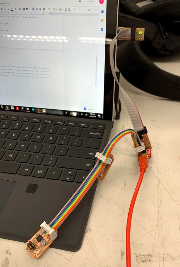
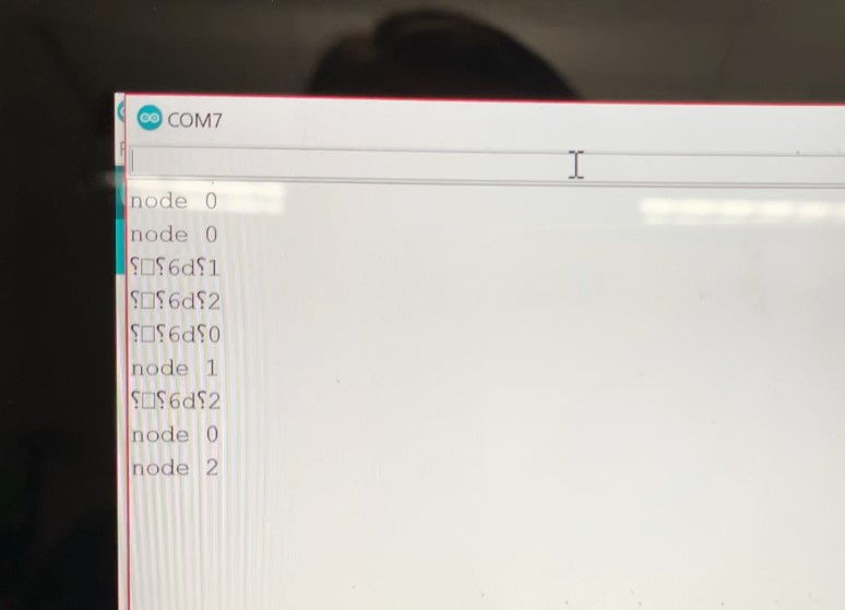
Everything looked ok when I was uploading the code, in fact all three boards went smoothly with no issues. When I actually tried communicating with them through the serial monitor, though, I kept on seeing these weird symbols.
The video below shows this weird behavior. You’ll notice that the leds are lighting up when they are supposed to, and the one that I call out to specifically blinks twice, this is how it’s supposed to be. The issue is that my serial communications are all jumbled up. Sometimes, (rarely), the message would come through clearly, but more often than not there would be a jumble of symbols followed by just the node’s ID.
The Issue
For two reasons, this leads me to believe that the issue is in the timing between serial communications. First of all, the leds on the boards are all working as intended. They all turn on once when they receive a message from the host board, then the individual board that is being called out to blinks a second time in response. This means that it’s not a hardware issue, because the chips are sending and receiving the signals as intended, and that’s shown by the blinking of the leds. I explain this further below.
At first I was thinking that if the signals between boards aren’t timed just right for serial communications, then the boards wouldn’t be working at all, and therefore the leds themselves wouldn’t even be turning on. The issue with that theory, though, lies behind the reason why the leds turn on in the first place. The first time the led turns on, it’s because it received some sort of signal, and this signal doesn’t necessarily have to be correct, it just has to be received. The second time the led turns on is because the chip sent a message back out, and once again this signal doesn’t necessarily have to be correct, it just has to be sent.
This, coupled with the fact that the symbols you see in the serial monitor are commonly caused by timing errors in serial communications, leads me to believe that the signals, while they are being sent between the boards, aren’t being sent correctly. The timing between signals is off somewhere, and this causes the serial monitor to interpret them as random characters that no one can understand.
Powershell
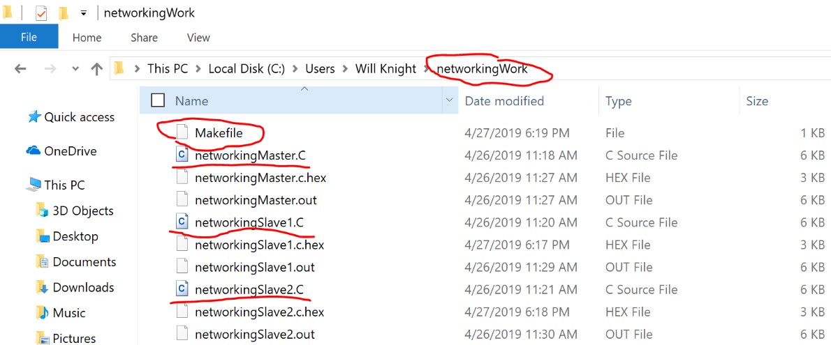
This was pretty confusing because everything looked right in the code and the bootloader and all of that. I had the right clock speed, I had the right baud rate, but regardless of this it was still messing up sometimes. I didn’t really know where to go from here except for maybe trying to program the board in a different IDE? I figured if I was going to do this I should put my powershell skills to use, so I got a makefile ready and made a new folder in my computer to work from.
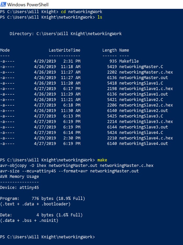
Then I hooked up my boards to my programmer, opened up powershell, and navigated to the correct folder from there.
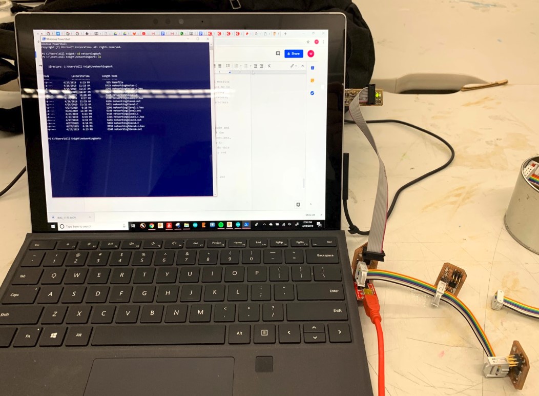
Next I ran the makefile to generate the hex and out files.
Then I entered “make program-usbtiny” and got the code uploaded to my board.
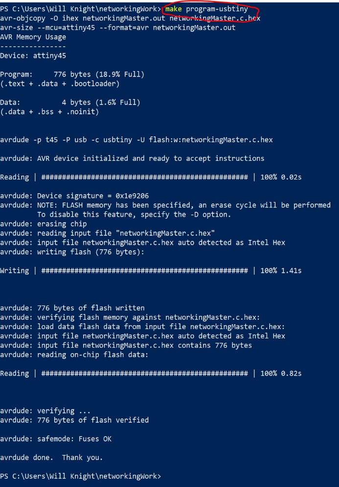
I did the same thing for the rest of the boards, changing the makefile as I went to use the correct .C file for each board individually. Once I was done, I hooked everything up to my computer and tried sending a communication through the serial monitor. This time, it worked!
I’m not entirely sure why this would work when the Arduino IDE didn’t, but I’m glad that I’ve learned how to program through powershell now more than ever. Everything has been running smoothly since then, and I’ve only had one more of the timing errors so far out of the many many times that I have sent signals.
Extra Nodes
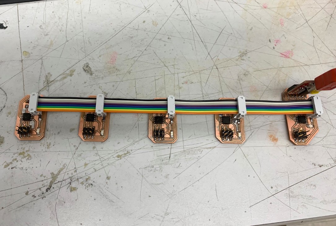
I had completed the assignment at this point, but I still had the parts and boards leftover to make two more nodes, so I went ahead and did just that. It didn’t take me long to get everything soldered together, then I programmed both of the boards with their own ID’s, (3 and 4 respectively), plugged them up with a new serial bus cable I made that has five connection headers, and started sending messages successfully!
Here are all of my files from this week.