4. Computer controlled cutting
Assignment
This week we had both individual and group assignments to work on. Individually, my assignment this week was to cut something on the vinyl cutter, as well as to design, lasercut, and document a parametric press fit construction kit which accounts for the kerf of the laser and that can be assembled in multiple unique ways. As a group, our assignment was to characterize our laser cutter by making test parts which varied in cutting settings as well as in dimension.
Vinyl Cutter
I started this week out by getting to work with the vinyl cutter. The cutter that we have in our lab is the Silhouette Cameo 2, and the cutter that I have at home is the Silhouette Cameo 3. I ended up using both interchangeably this week, but that wasn’t an issue because the only key differences are the range of cuttable materials as well as the size of the cutting space. For the sake of only cutting out vinyl, both machines operate virtually the same and both will use the same software called Silhouette Studio.
You can find more about Silhouette America here.
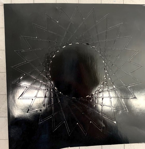
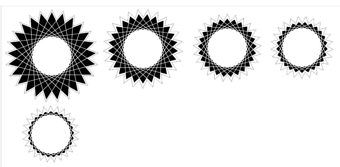
The first thing I did was get a design drawn out in CorelDRAW that I wanted to cut for my sticker. I started this by drawing out two shapes, one slightly smaller than the other, with the “Complex Star Tool”, pictured below.
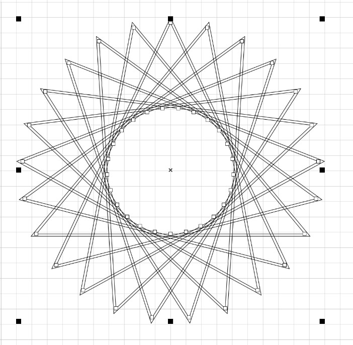
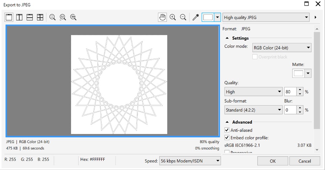
Then, I used the virtual segment delete tool to trim away unwanted lines inside of my pattern. This took quite a while. After getting my file all cleaned up, I then exported it out of CorelDRAW as a JPEG file.
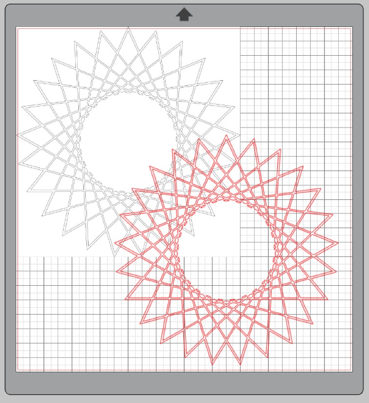
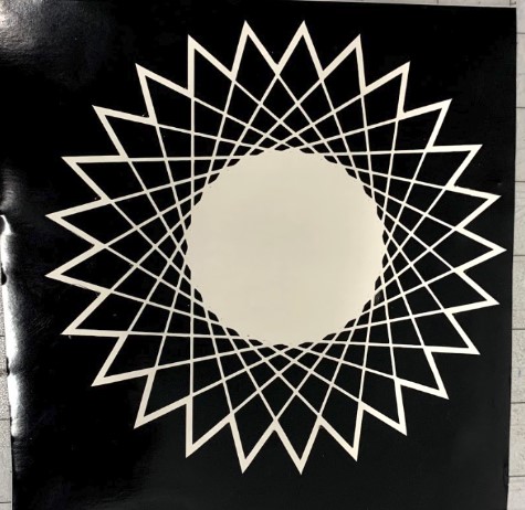
After pulling it up in Silhouette Studio, I then had to trace the jpg file to get cuttable lines that the vinyl cutter can work with. To do this, I opened up the trace panel in the Silhouette software and clicked “select trace area”. After selecting my design, I chose “trace” under the style options and the software made cut lines from my design. In the photo below, the original JPEG is in black and also has a white background which covers up the grid behind it, and the trace is the design with red lines.
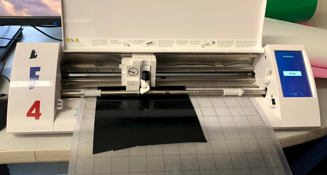
Next, when I had a cuttable pattern ready to go, I connected my computer to the Cameo vinyl cutter and got it ready to send over. The cutter itself is very intuitive to operate, the only real hands on work that you have to do with the machine is loading in the cutting mat. These mats are very useful because they have a slightly sticky side that holds down the vinyl piece to keep it from bending up and ruining the cut mid progress. All that’s left to do after loading the cutting mat is to simply press send in the Silhouette Studio software and the cut will start going right away.
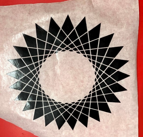
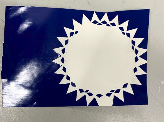
After the cut finished up, I realized that the very innermost ring of diamonds was so small that they got messed up and pulled away by the cutter, but the design still looks great without them anyways. After weeding the rest of the design, this is what I was left with.
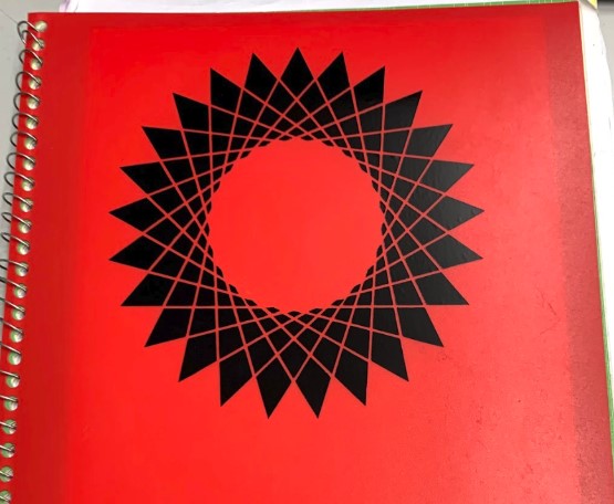
I then used a type of transfer paper to only pick up the parts of the sticker that I needed. Transfer paper makes it super easy to perfectly place complex designs right where you want them.
Finally, here is the end result. I put it on one of my folders for school and it looks great.
After a bit more thinking, I wanted to go further with my design. Instead of just having an all black sticker, I want to use different colors of vinyl for each ring so that is has a nice gradient to it. I went back into Corel and started deconstructing my pattern so that I could cut out the differently colored rings as necessary. This is what I was left with after that.
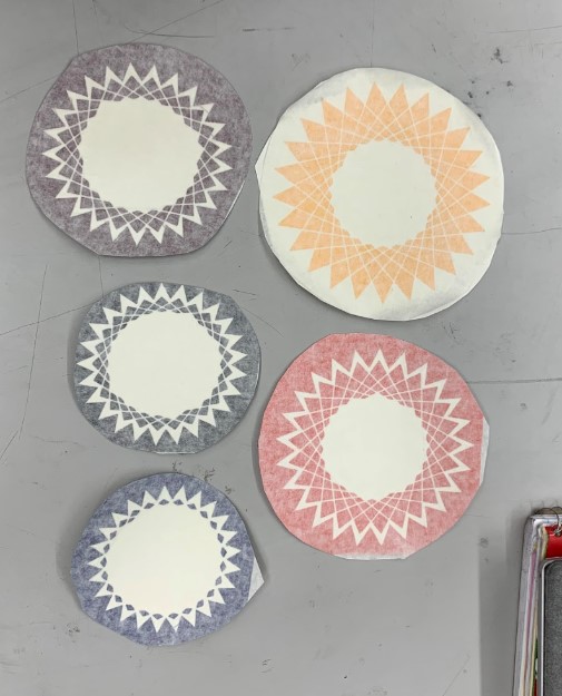
After getting each set of rings ready, I sent them over to the vinyl cutter again individually and cut them all out in different colors. Once all of the cuts were completed, I weeded out the designs and was left with these.
I had to run a few of the cuts twice because when the cutter was going it would occasionally pull a few of the small pieces away along with the blade as it moved. This is what one of those inconveniences looked like.
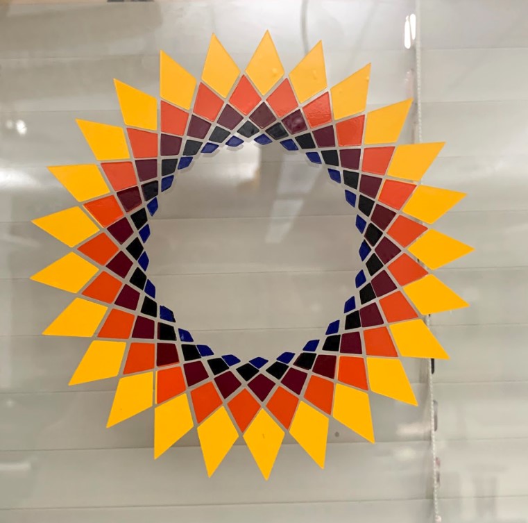
After getting every ring cut, I then had to weed out all of the diamonds that I didn’t need from each ring. This took quite a while and involved a TON of tiny stickers, but after seeing the final result it was well worth it.
Laser Cutter
The next thing I worked on this week was my parametrically designed laser cut construction kit. I looked around at some of the previous kits that people have made in past years to give myself a bit of inspiration, and then once I understood what I was really trying to make I got to work on the design.
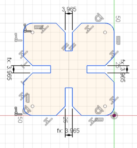
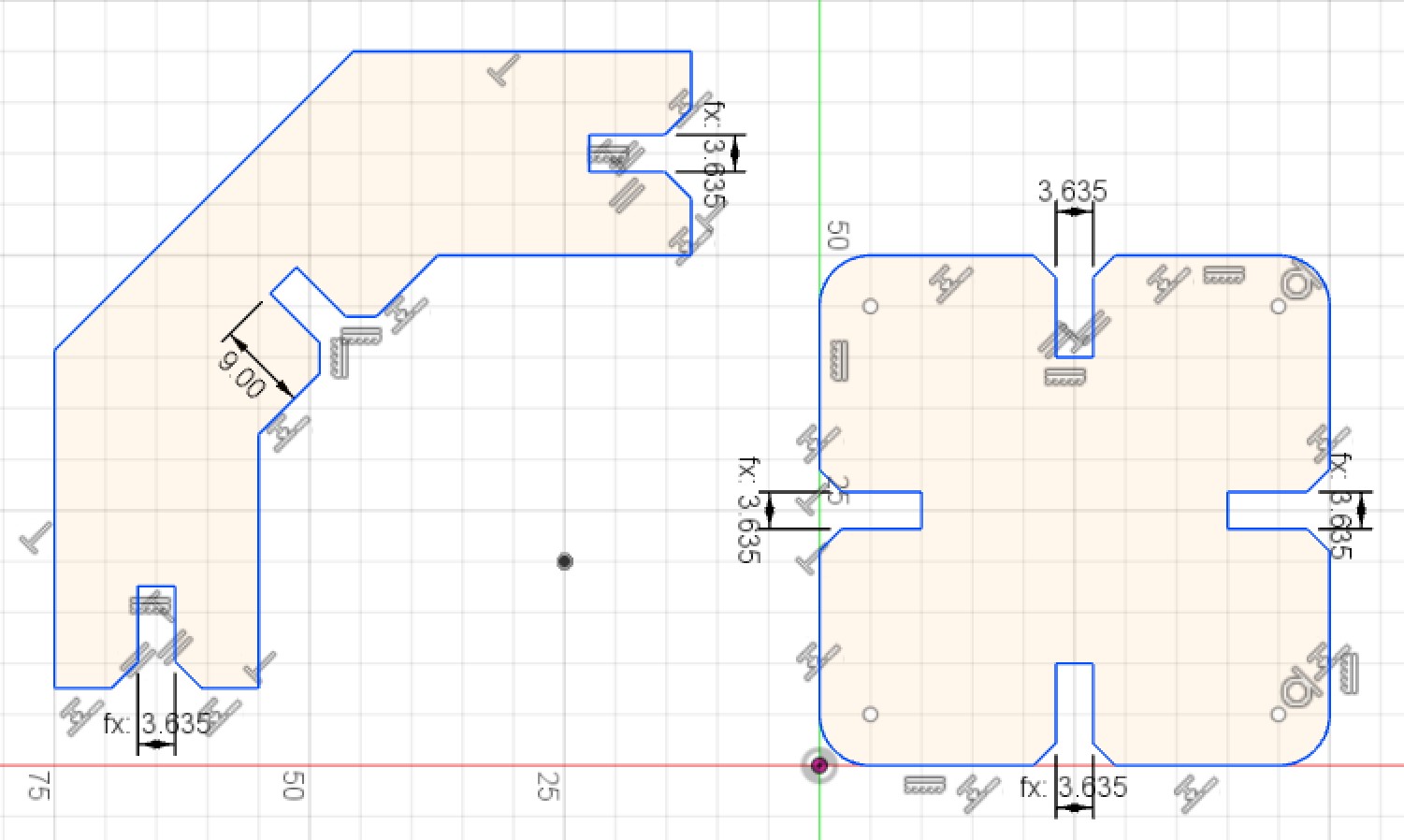
I wanted to make the design in fusion because that’s what seemed easiest to use and work with when it came to parametrics before. I started out in the sketch environment and got the first shape drawn out.
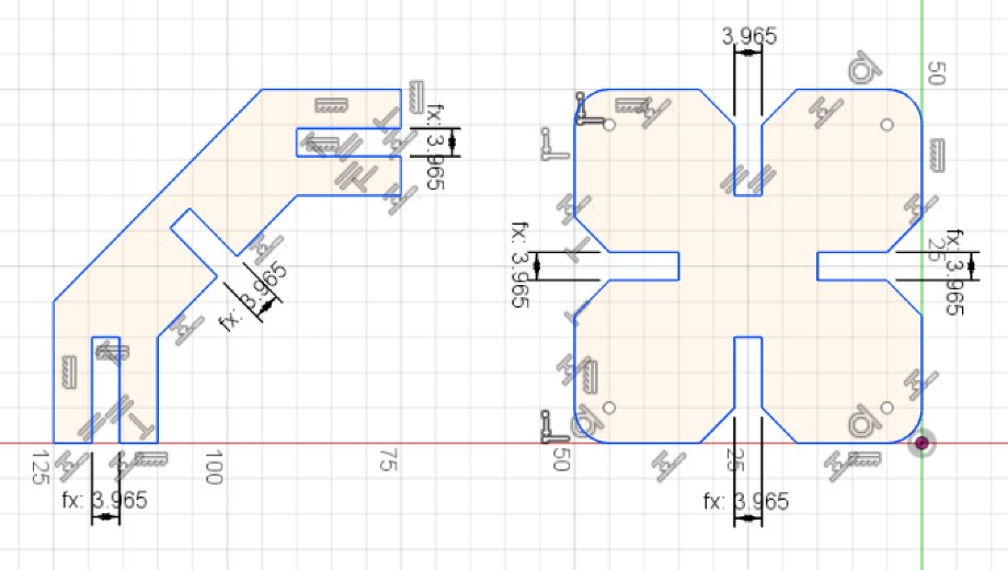
Next, I made the second (and last) shape for my kit. This is also pictured below.
Both of these shapes are designed parametrically, which means that I can change the dimensions of one of the press fit gaps, and the dimensions of every other gap will change along with it. This is extremely useful when you want to make one design work with many different materials. All you have to do is measure the thickness of the material you want to use in that instance, input the thickness you got over to one of the gaps in the design, and watch as every other gap automatically resizes itself because the project was designed parametrically. It really is a very helpful concept to understand.
One other thing I had to account for was the kerf of the laser itself. The laser cutter doesn’t just separate material into two pieces the same way a blade does, it actually destroys the material that’s in its way through a process called laser ablation. The laser basically just gets rid of whatever is in its path, and when you get down to very precise fits and measurements, that can make a difference. For example, if you were to cut out a circle that’s supposed to measure 1 inch in diameter, you would actually be cutting out a circle with a diameter that is 0.015 inches less than 1 inch.
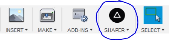
After I had the two shapes for my construction kit made and ready to go, I needed to somehow send the file over to CorelDRAW because that’s what we use to communicate with the laser cutter in our lab. To do this, I installed an add-in for fusion called Shaper Utilities which you can find here. What it does is let you easily export sketches out of fusion as an SVG file, which means I now have a way to bring my models over to CorelDRAW.
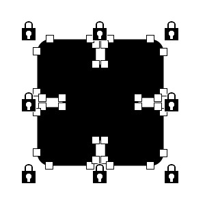
After saving as an SVG and then opening the file in corel, I had to unlock the svg so that I could make changes to it.
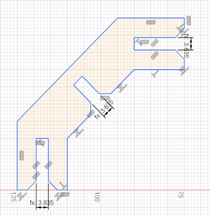
Upon unlocking the SVG in Corel, I suddenly realized that I had forgotten to chamfer the edges of the leg of my design, so I went back into Fusion and made those adjustments.
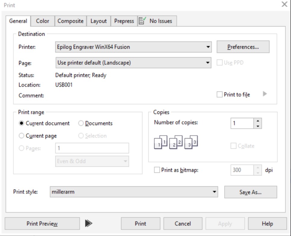
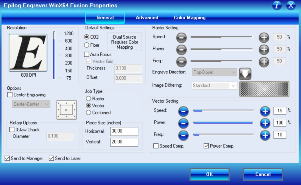
After getting the designs all set up in Corel to be cut, I opened up the print window and made sure all of the necessary settings were correct. Under the print window, select preferences to change the the speed, power, and frequency of the laser.
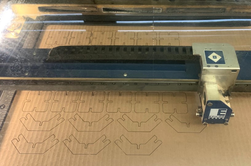
After making sure the settings were all corect on the software side of things, I then moved over to the actual laser itself and began getting it ready. It had already been in use by other classmates, so all I did was focus it for my material, which was cardboard, and then jog the homing point over to work for my cut.
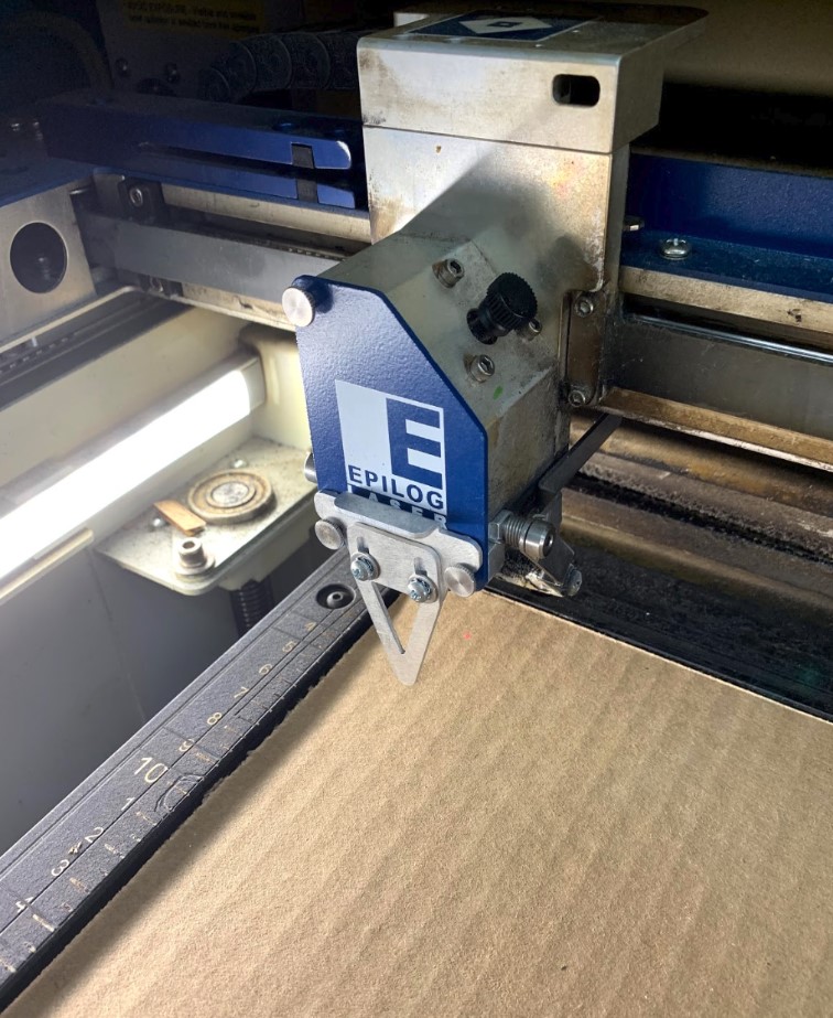
Once everything was set and ready, I hit go on the laser cutter and let the machine do the rest of the work for me.
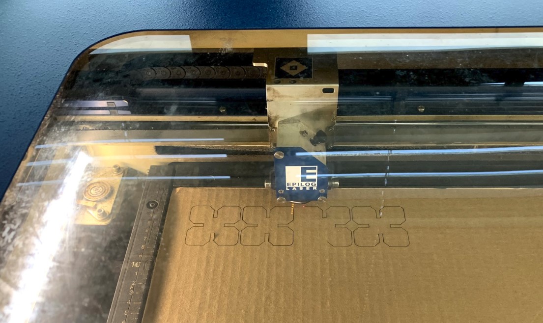
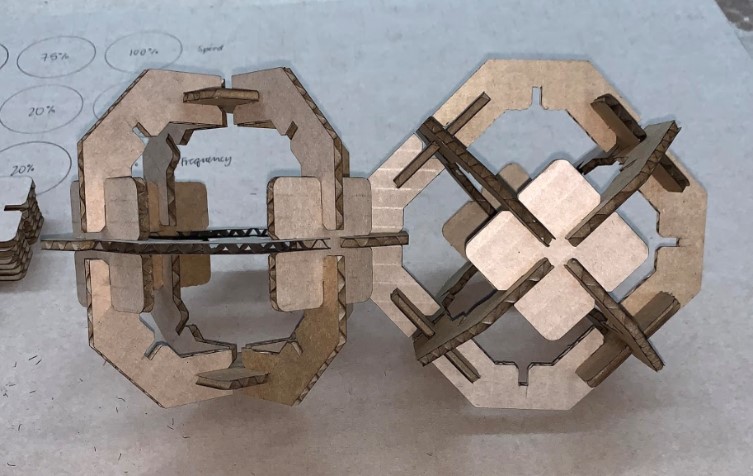
Unfortunately though, Once the cut finished up I recognized the first of my two problems. I only did one pass on the cardboard with those settings which meant the laser wasn’t quite able to punch all the way through the material on some of the pieces.
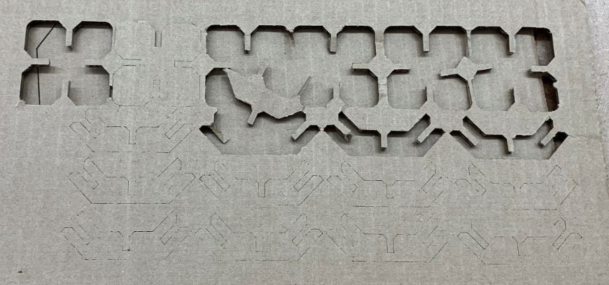
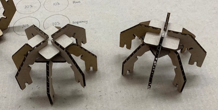
Thankfully, this didn’t happen to every single one of my pieces so I was able to get a few of the shapes into my hands. After messing around with them for a bit, I recognized the second of my two problems. Even though the pieces all fit together very well, I didn’t size the core shapes correctly which lead to the legs running into each other when you pressed them together.
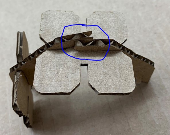
Obviously, this was an issue, so I quickly made a couple more models with parametric design that would actually fit together correctly and work well.
After I was sure that this design version would work, I went through the same process mentioned before to get the file set up in Corel and ready to cut. This time, I ran a second pass on the laser cutter to make sure everything was properly cut out, which worked very well and left me with all of the pieces I needed.
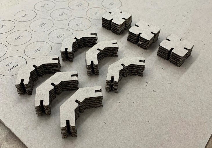
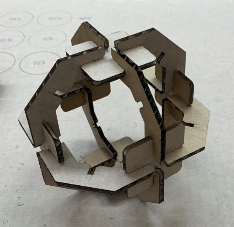
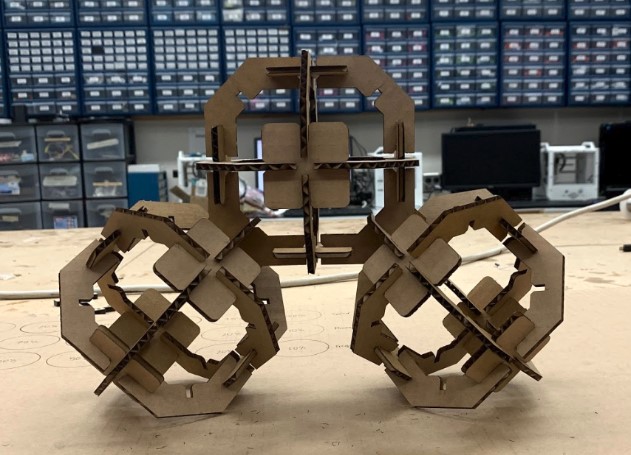
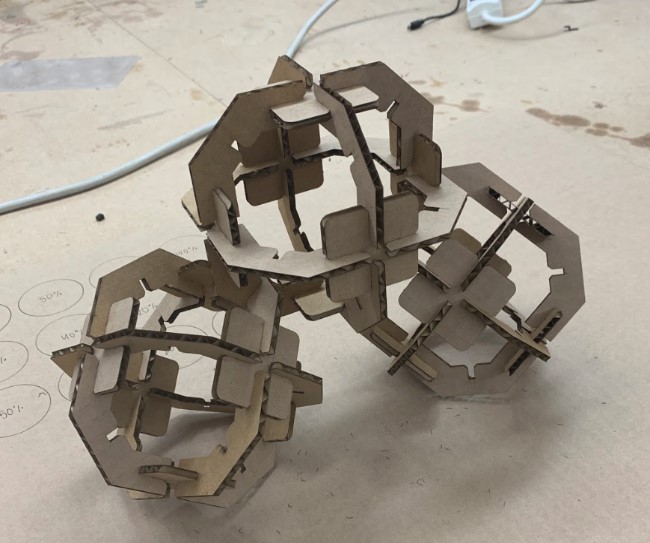
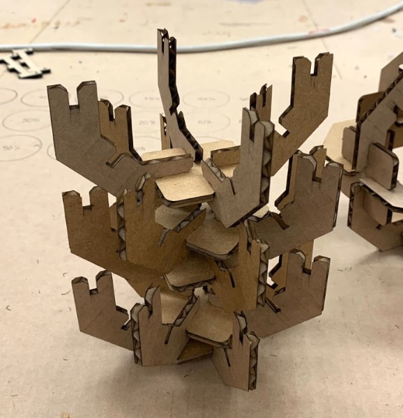
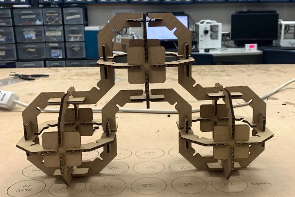
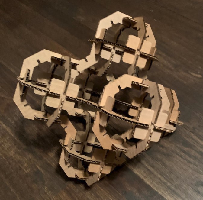
I’m really happy with how this project finished up as well. I spent over an hour messing around with the shapes just seeing what I could make with them, and I’ve included some of the highlights below.
Group Project
EDIT: The following information is still relevant, but not correct. I realized a few issues after meeting with my instructor and have included accurate information below.
The final thing to work on this week was the group project of characterizing our laser cutter. Unfortunately, due to a communication error, I was not there when my fellow classmates worked on this, but to keep myself from just taking all of their findings as my own, I’ll be re-working the measurements for the kerf of the laser so that I can determine it in metric units, which is what I like to use whenever possible.
To determine the kerf of the laser, my classmates cut out what was supposed to be a 2x2 inch square. In metrics, this square would therefore have side lengths of 50.8mm. When I went to measure the square, though, it actually measured less for one side’s width than the other.
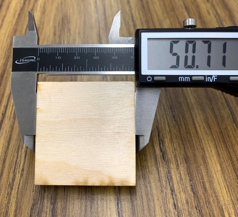
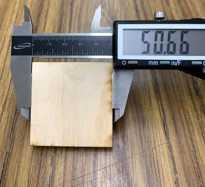
The measurement off of one side of the square showed that the kurf was taking away 0.09mm of material, whereas the other measurement showed that the kurf took away 0.14mm of material. To give you an idea of just how small were talking here, the thinnest edge of a credit card is usually ~2.00mm thick. To get the best possible measurement for the kerf of the beam, I averaged both together and found that the laser has a thickness of 0.115mm.
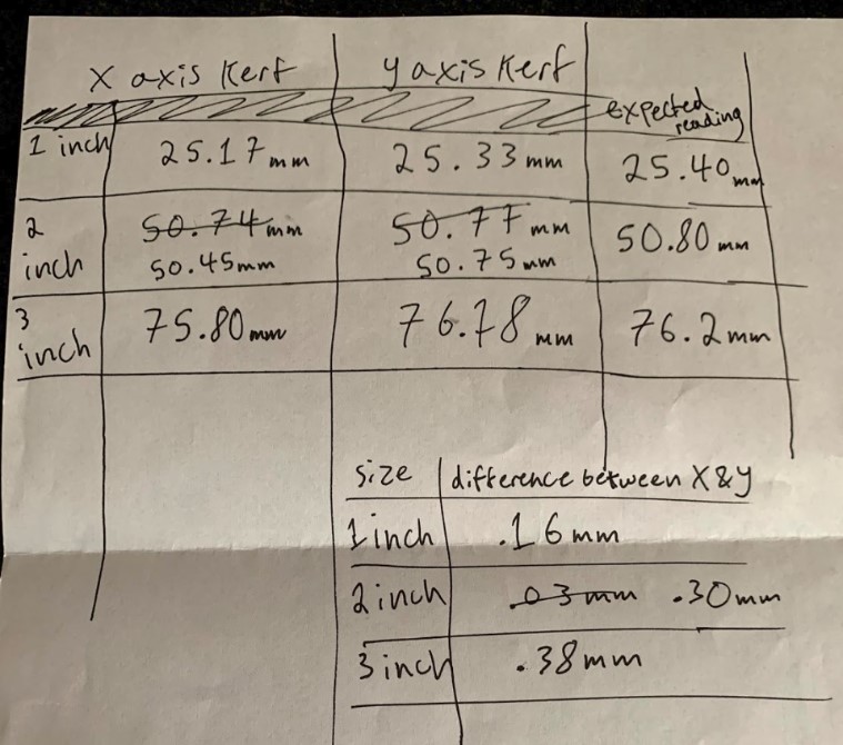
After meeting with one of my instructors, he brought it to my attention that there really shouldn’t be a difference in the kerf regardless of which side of the square I measured. He suggested that rather than trying to find the kerf for now, I should instead try to identify more about the issue that caused the previous variance in measurements. He figured that it was probably one of the belts being off a bit, and suggested that to find out which axis was causing the problem, I should cut out three squares of increasing size. With these three squares, I could then see which axis had a consistent kerf, and which axis was dropping off more and more because of how the belt issue would compound on itself as the size of the cut increased.
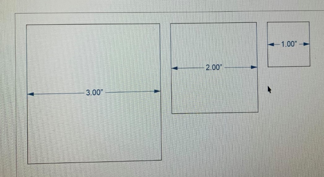
To do this, I drew out three squares in CorelDRAW sized at 1, 2, and 3 inches respectively.
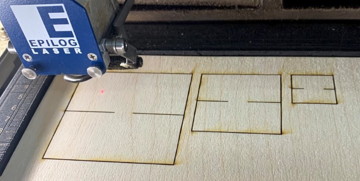
Then, I went through the same process as before of getting the cut sent over to the laser. Once everything was set I began the cut, but as you can see below the dimensions from the document actually got cut out by the laser itself as well, meaning there were a few extra passes where there shouldn’t have been any at all.
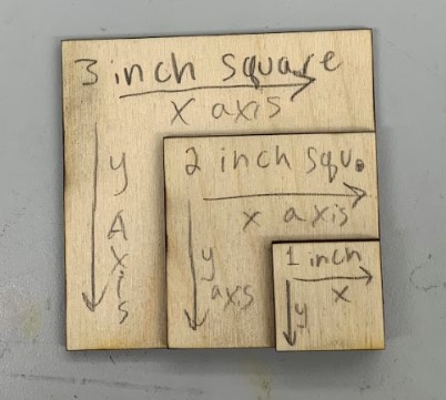
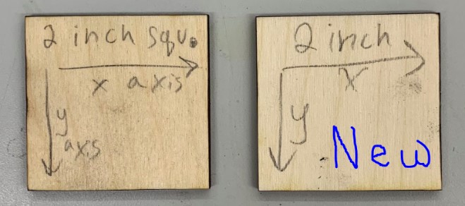
To fix this I just went back over to corel and removed the dimensions, then I got the cut prepared and started a second time. It took 2 passes to cut out, and after getting them cut I made sure to distinguish which side was cut off of the X axis and which one was cut off of the Y axis.
When I took the squares out to measure them, I realized that the dimensions I was getting off of the 2 inch square were not adding up with everything else. I checked the square out to see what could have been the issue and I think that what happened was that the beam of the laser lined up perfectly along the grain of the plywood as it cut out one of the sides, causing one side of the square to burn at a faster rate and therefore lose more material to the ablation process. I cut out another 2 inch square and this time everything lined up as expected.
Doing these tests for the cutter let me see a lot of things. I organized some of the data I got and was able to determine that it is the X-axis belt which is causing the issues.
The other thing my classmates did to help characterize the laser cutter was to run a series of test cuts at varying settings. The three main settings to think about when operating the laser are speed, power, and frequency. Speed controls the speed with which the laser cuts out material, power controls how much power the beam is actually using, and frequency affects how often the laser actually fires. To show how changes in each of these settings can affect a cut, they created three rows, one for each setting, of circles. Each one starts at the standard setting and then increases a specific setting the farther along that row you move.
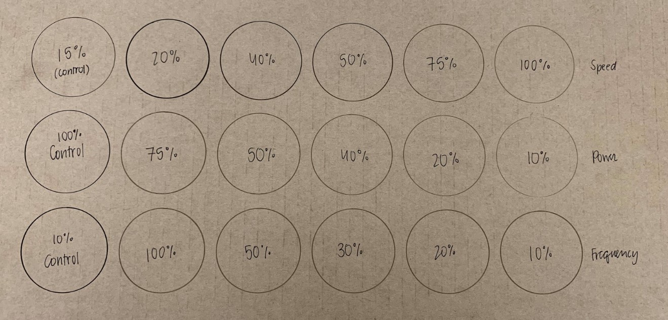
This has been very helpful because it shows me how certain settings may actually look before I even run my cut. With this around, there is less guesswork involved when working with new materials, too.
Here are all of my files from this week.