EMBEDED PROGRAMING
9.WEEK
This assignment was like attachment to “Electronics design” where we were making Hello world board. At the end it was great task, so that’s why I suppose this one is also going to be. Reading the tasks, individual, where we need to read our microcontroller data sheet that we used for “Electronics design” and to study and explain it. Also for individual assignment is to program the board to do something, but to try it using different programming languages and environments.
And for the group task is to compare the preferences and development workflows.
So…let’s get down to business.
INDIVIDUAL ASSIGNMENT
First is to read data sheet of the microcontroller, so I looked up in ATMEL data sheet for my ATtiny44 that I used for my hello world board. Right a way on the first page there is whole list of Atmel features for ATtiny24A/44A/84A.
Because I’m still new to this world, I really put my head into it to understand it from top to bottom. First thing that is important is Pin configuration, every pin has it’s own “job”, so let’s se how are the pins for ATtiny ordered.
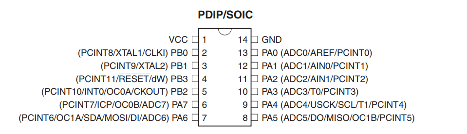
As you can see the pins are separated in groups:
VCC-supply voltage
GND- ground
RESET-reset input, for resetting when the pulse is longer than the minimum pule length and it also can be used as a week I/O pin
Ports A (PB0-PB3): 8-bit bi-directional I/O port with internal pool up resistor
Ports B (PA0-PA7): 4-bit bi-directional I/O port with internal pull-up resistors, can use PB3 as RESET capability or as I/O pin
There is one thing that I didn't put earlier and that are ADC pins, it's short for Analog to Digital Converter and it means as it says, to convert analog signal into digital.
ATtiny24A/44A/84A are as I wrote before, low-power CMOS 8-bit microcontrollers based on the AVR enchanced RISC architecture that uses Harvard architecture in order to maximize performance and parallellisam.
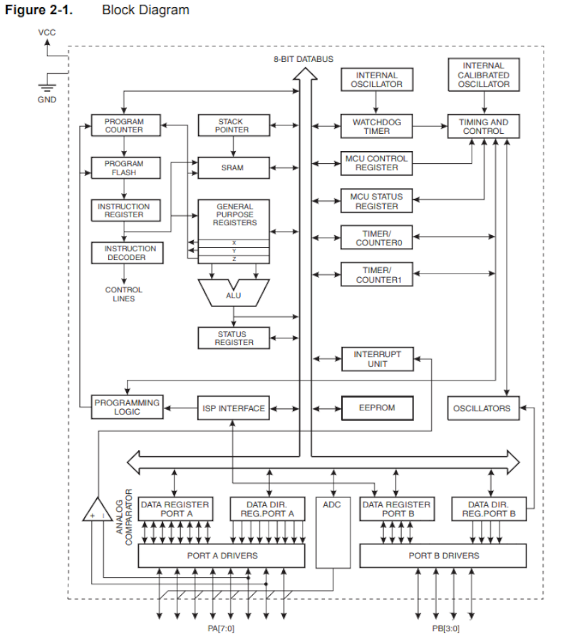
After learning about ATtiny microcontrollers I can continue to programing one and try different cods and languages.
PROGRAMMING
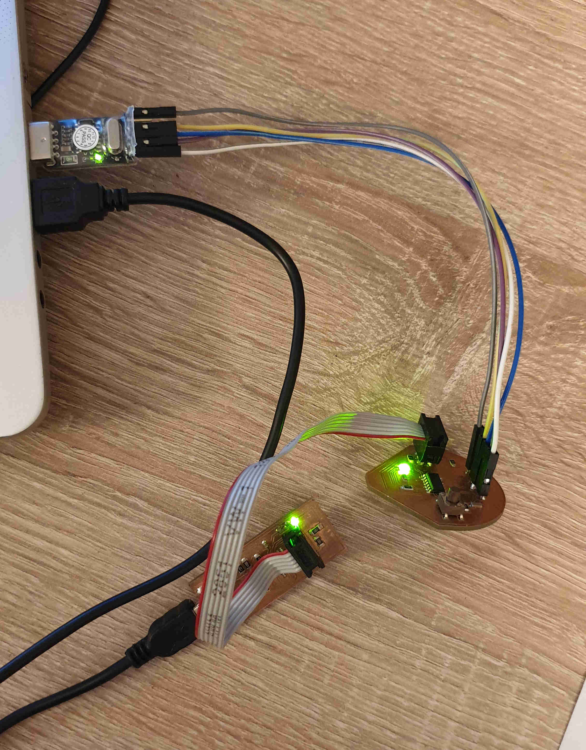
For this part I need my Hello board connected to my computer so I can try to program it a little bit more. I need to have in mind that I can use LED and BUTTON on my board. First I'll go for Arduino IDE and than try to progrem it with C.
Arduino IDE
I’m already familiar with Arduino IDE because it was our task for Week7, so I connect my board, opened a Arduino IDE, went on “File>Examples>Basics>Fade”, for first attempt I tried code for fading the LED. But before I can upload it I need to look at the schematics first to make sure where my LED is, on which pin. And for me it is on pin 7, the fade amount I leave it like basics but it can be configurate.
/*
  Fade

  This example shows how to fade an LED on pin 9 using the analogWrite()
  function.

  The analogWrite() function uses PWM, so if you want to change the pin you're
  using, be sure to use another PWM capable pin. On most Arduino, the PWM pins
  are identified with a "~" sign, like ~3, ~5, ~6, ~9, ~10 and ~11.

  This example code is in the public domain.

  http://www.arduino.cc/en/Tutorial/Fade
*/

int led = 9;           // the PWM pin the LED is attached to
int brightness = 0;    // how bright the LED is
int fadeAmount = 5;    // how many points to fade the LED by

// the setup routine runs once when you press reset:
void setup() {
  // declare pin 9 to be an output:
  pinMode(led, OUTPUT);
}

// the loop routine runs over and over again forever:
void loop() {
  // set the brightness of pin 9:
  analogWrite(led, brightness);

  // change the brightness for next time through the loop:
  brightness = brightness + fadeAmount;

  // reverse the direction of the fading at the ends of the fade:
  if (brightness <= 0 || brightness >= 255) {
    fadeAmount = -fadeAmount;
  }
  // wait for 30 milliseconds to see the dimming effect
  delay(30);
}
Here you can see the result of that. It's not much but it's cool.
Now I wanted to add the function of button also, so I searchet again in examples and found under digital "Button", again need to change pin for LED and also for button. And thatn I'm good to go for uploading.
/*
  Button

  Turns on and off a light emitting diode(LED) connected to digital pin 13,
  when pressing a pushbutton attached to pin 2.

  The circuit:
  - LED attached from pin 13 to ground
  - pushbutton attached to pin 2 from +5V
  - 10K resistor attached to pin 2 from ground

  - Note: on most Arduinos there is already an LED on the board
    attached to pin 13.

  created 2005
  by DojoDave <http://www.0j0.org>
  modified 30 Aug 2011
  by Tom Igoe

  This example code is in the public domain.

  http://www.arduino.cc/en/Tutorial/Button
*/

// constants won't change. They're used here to set pin numbers:
const int buttonPin = 2;     // the number of the pushbutton pin
const int ledPin =  13;      // the number of the LED pin

// variables will change:
int buttonState = 0;         // variable for reading the pushbutton status

void setup() {
  // initialize the LED pin as an output:
  pinMode(ledPin, OUTPUT);
  // initialize the pushbutton pin as an input:
  pinMode(buttonPin, INPUT);
}

void loop() {
  // read the state of the pushbutton value:
  buttonState = digitalRead(buttonPin);

  // check if the pushbutton is pressed. If it is, the buttonState is HIGH:
  if (buttonState == HIGH) {
    // turn LED on:
    digitalWrite(ledPin, HIGH);
  } else {
    // turn LED off:
    digitalWrite(ledPin, LOW);
  }
}