COMPUTER CONROLLED MACHINING
8.WEEK
For shure I can say that this is my favorite assignment by now. It’s make something big this week so let’s get down to business. Unfortunately we don’t have big CNC at Bottrop, so colleague and I drove to the FabLab Kamp Lintfort witch is part of Hochschule Rhein-Waal where we got help from their instructors Ahmed and Marcel, so big thanks to them for helping and making sure that we understand everything and that we are using machine correctly and safely.
GROUP ASSIGNMENT
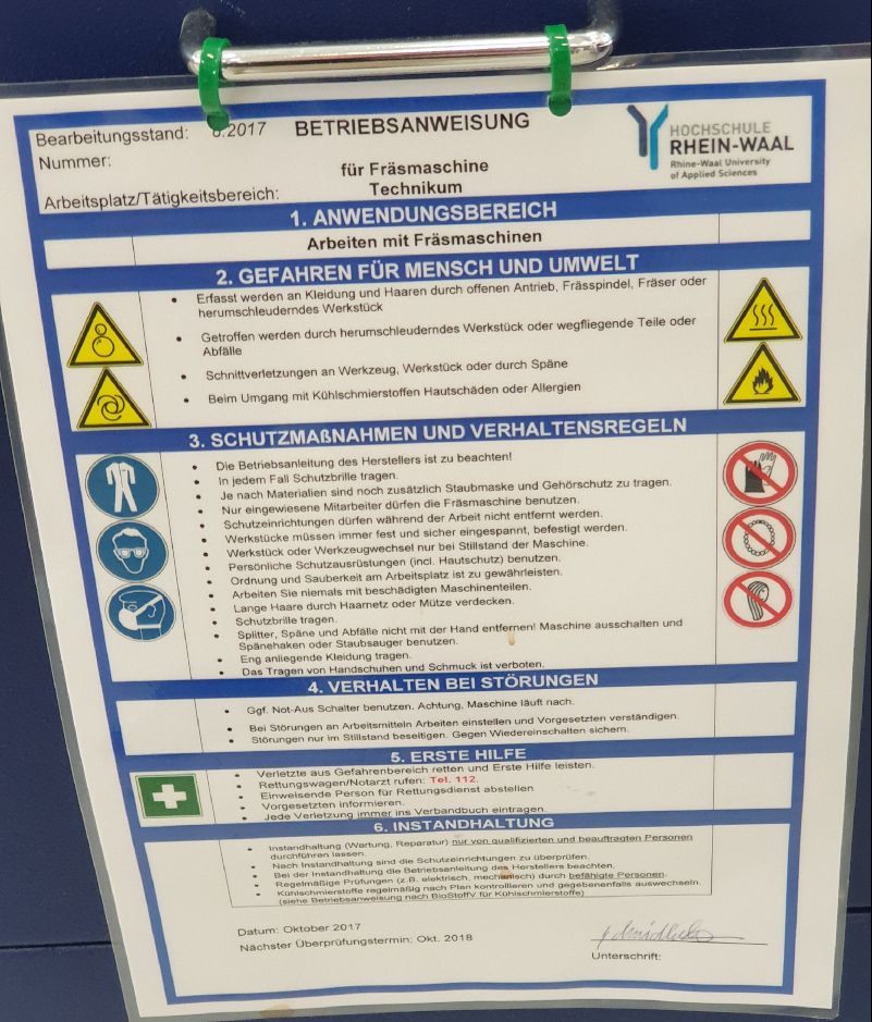
Before turning on the machine we need to know all the safety procedure and really be careful when we are using the machine. So Ahmed got us trough the whole safety procedure step by step and I think the most important rule is to all the time have our eyes on the machine when the machine is working, so in case something goes wrong we can react in shortest time.
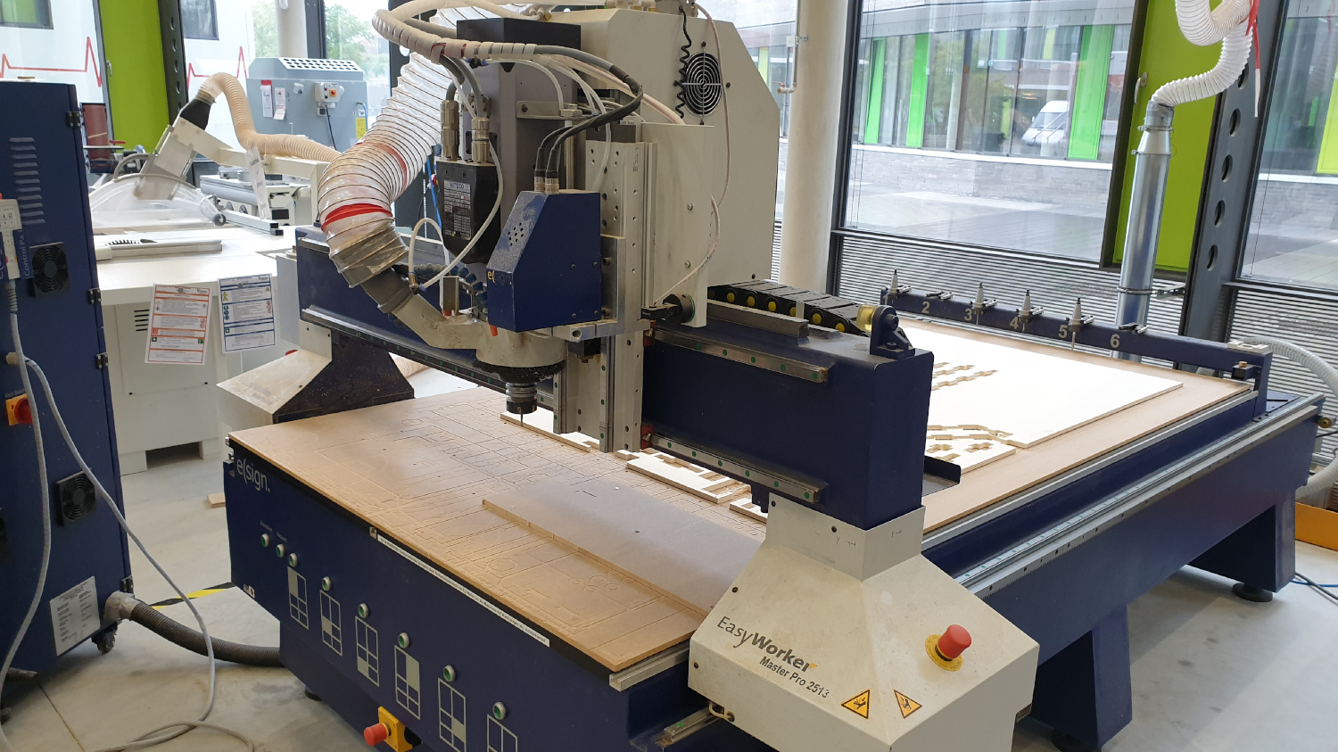
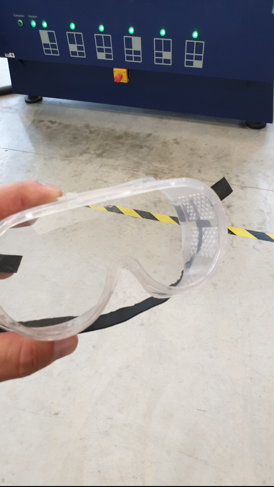
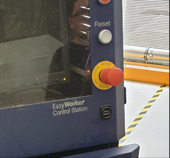
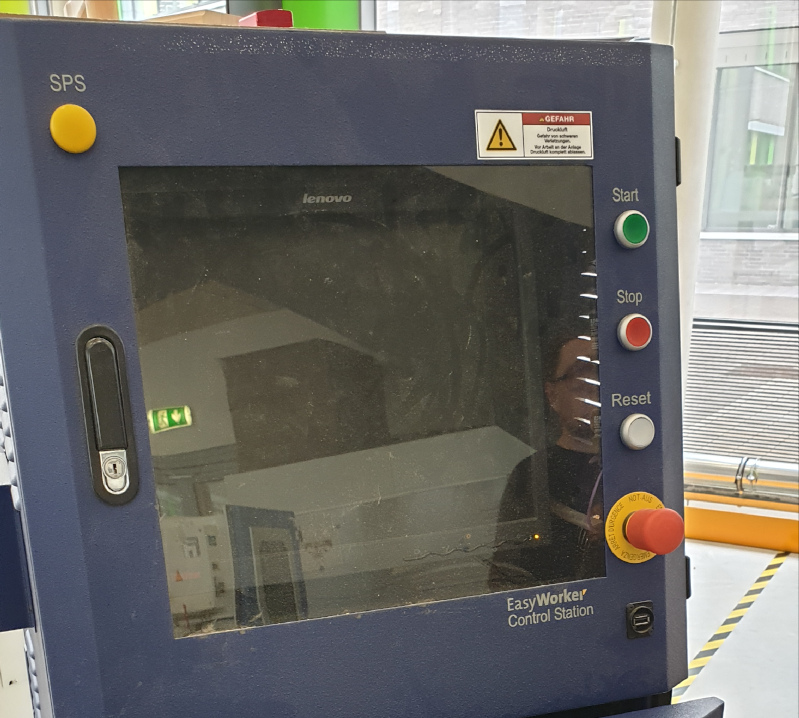
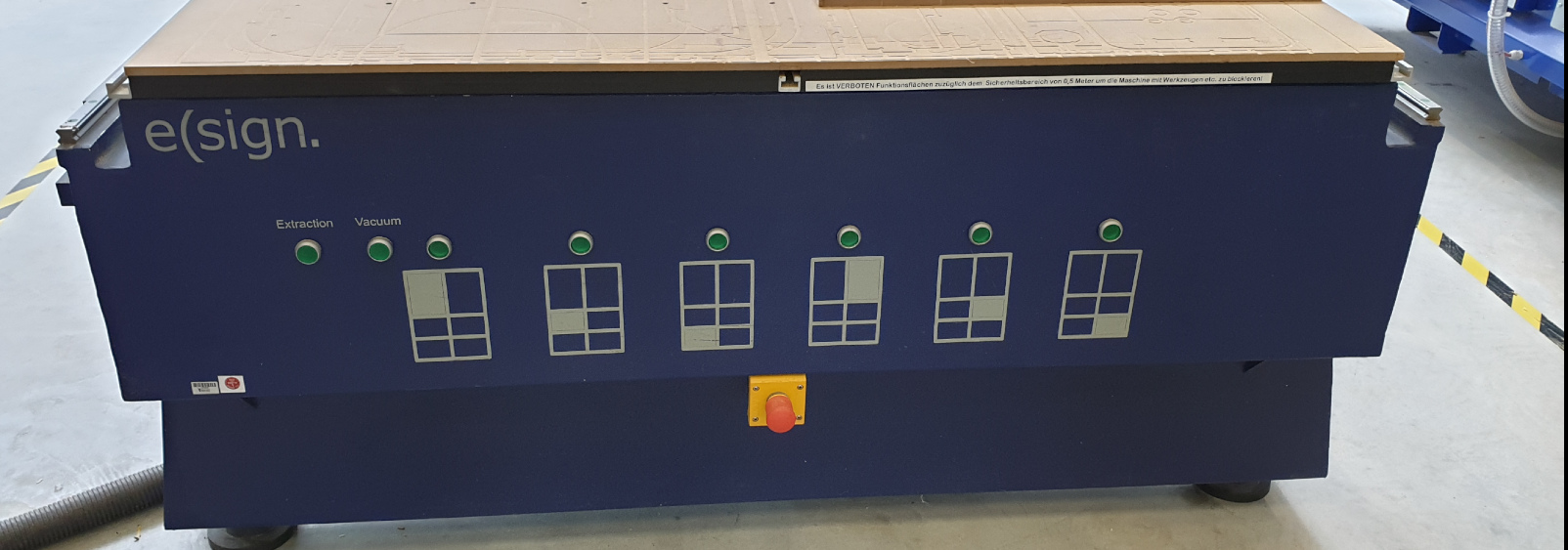
Machine that we are using is Easy Worker Master Pro 2513. Mayor rules for handling the machine: Always wear the protection glasses and ear plugs or ear covers when the machine is working and newer cross the line on the floor when it’s working. We were also told that there is several emergency buttons on the machine in case of failure, just like one below.
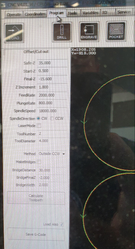
Now after I know how to handle it safely I can get to work and first test some of futures of the machine. We need to be careful when we are measuring parameters that we are going to put in the program, because it can cause some errors like in my case that I’ll show latter. So here are some of the parameters.
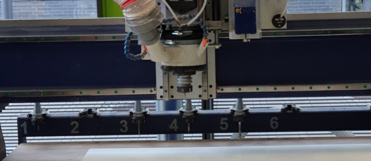
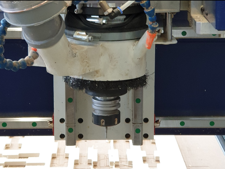
The size of the work bench is 2500mm x 1250mm and it has opportunity to use 6 different tools during one job. But for my test model and table I was using only tool number 2 witch is 4mm mill in this case.
To test the machine I wanted to see how much of the material is the tool taking or what is he deviation from original parameters. So I designed simple model in Fusion 360 and I was also able to see what was the thinnest dimension that we can mill with 4mm mill.
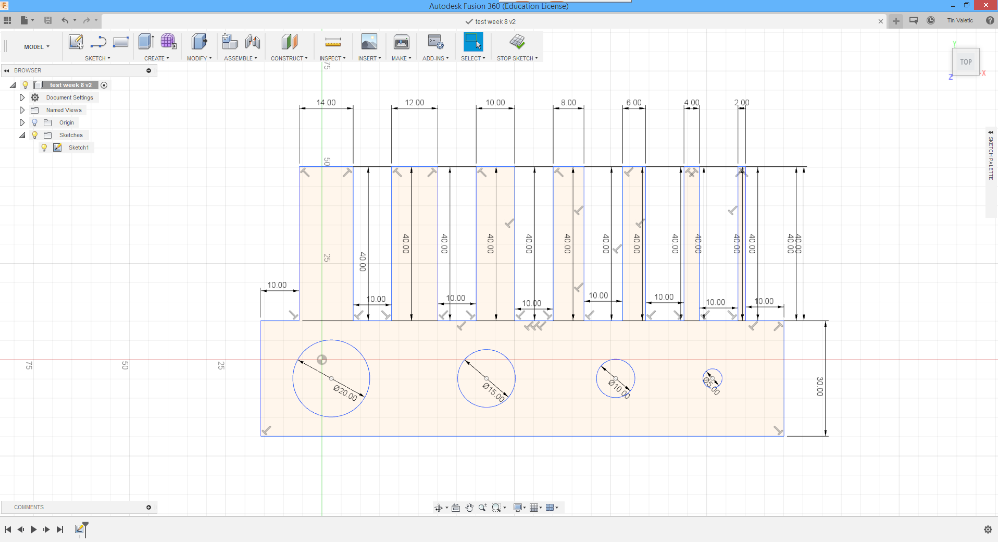
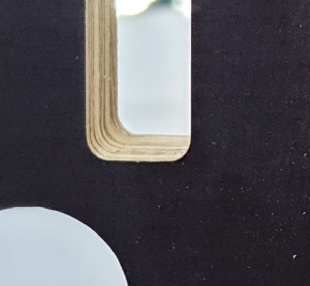
From this model it also can be seen why are we using T-bone structure for joints. It’s because in program we put the 90degree angle but the mill is round so it can not mill the right angle, so in the end if we don’t put T-bone structure we get round corners as it can be seen from the picture below.
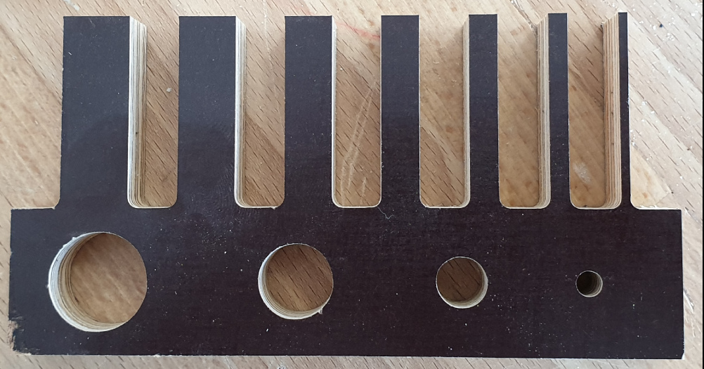
This test model looks perfectly milled, but don’t be so sure because there was two big errors due the job. First I putted wrong parameters for the Z axis, I putted too much and the tool got all the way trough second board but didn’t damaged the machine or the tool. Second the tool got stuck to the model and push the whole board to the other end of the machine, luckily there is lot of emergency red buttons so I pushed one in time to stop the machine. And third is not big error but I put in the program that tool goes from the inside to mil the holes. I was advised from my instructor that is better to tell the tool to go from the outside for bigger holes and to rather chose drilling tool for smaller holes…but in the end holes ended great.

INIVIDUAL ASSIGNMENT
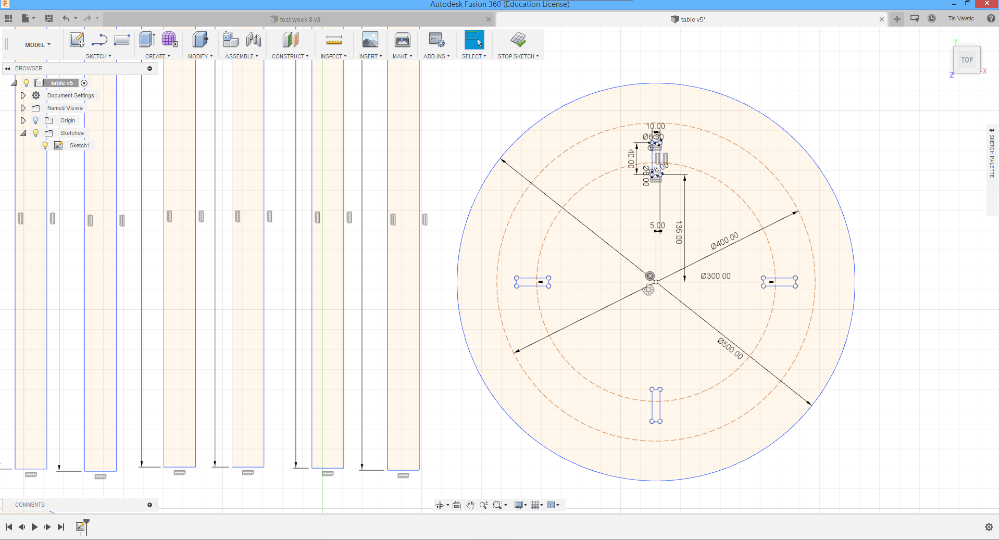
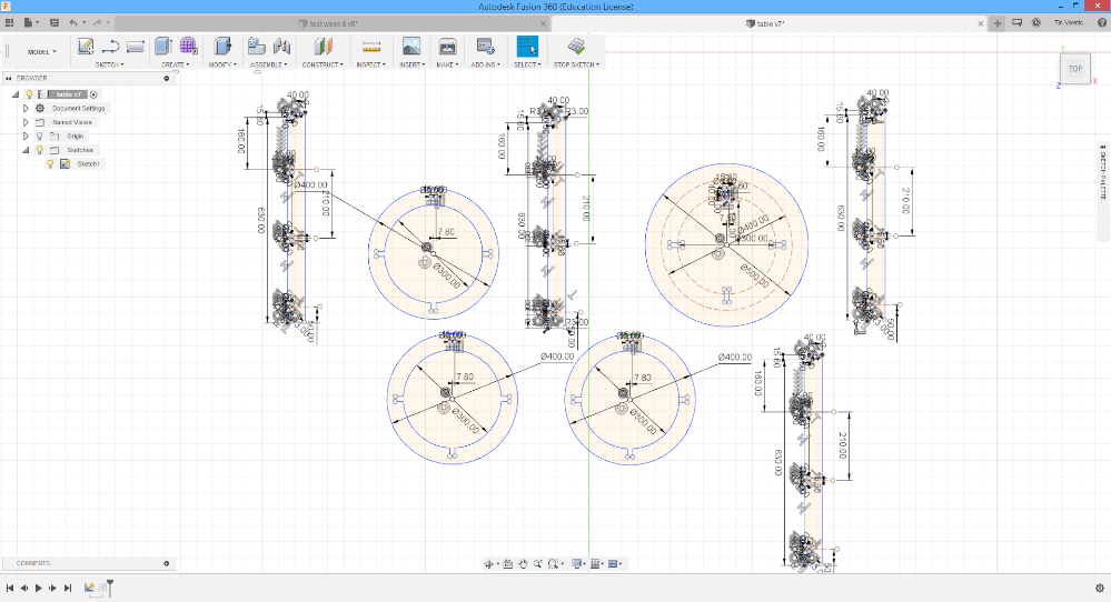
After getting trough security measures I’m ready to make my little table. I don’t have sketch on the paper for this one because idea got to my head while I was already in the program. So the first was to design my idea in Fusion 360 before I can move on to another step. On pictures below you can see all dimensions that was needed for my table.
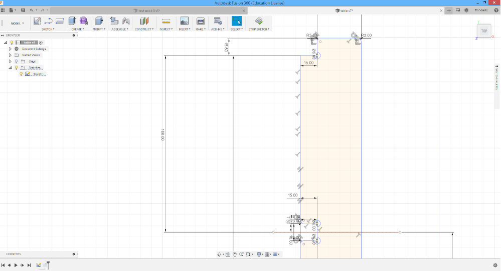
For this task I'm going to design only in 2D because for milling machine I need .dxf files which are 2D. At first picture I made circle that reprisent top of my desk. to do it you need to go on top toolbar and pres Sketch, under that is a lot of linear commands that you can chose, depends what you need.
Putting direct values is easy in Fusion, just select start oint and tipe value, softwer will automaticly set sketch on coordinates. Thise three dotted lines inside of my table are helping lines, tehy are helping me to orientate myself for other layers of table, because I'll need three more layers but only like a rings. Regular lines can be changed on right side "Sketch palette" and press first icon with dotted lines.
If you miss your dimensions, that's not a problem, pres right click on line that is first to measure than pop-up toolbar will show, press "dimensions" and than select second line and tipe value.
This picture is showing T-bone joints. I't really important to mae them for inner parts of joints because it allows second part to come all the way trough. They were also made with line comands and extralines were cutted with CUT command also positioned where the lines are.
Now to multiple legs and lower parts of table. Position and orientation of models are not important now because that step I'll make in Rhino3D. Before going on next step, just to double check all.
Next thing to do is export model to .dxf file, open Rhino3D software and import that file. We are using Rhino to se if there is everything oke with our model, to make shure that all the lines are connected and also to set the layers. First thing to do in Rhino would be to select everything and click on command “explode” than “join”, that allow us to se are the lines connected. Than we need to select everything with the different type of milling or drilling, for example we need one layer for the outer lines and one for inner lines, also one layer for holes and one if want to engrave something.
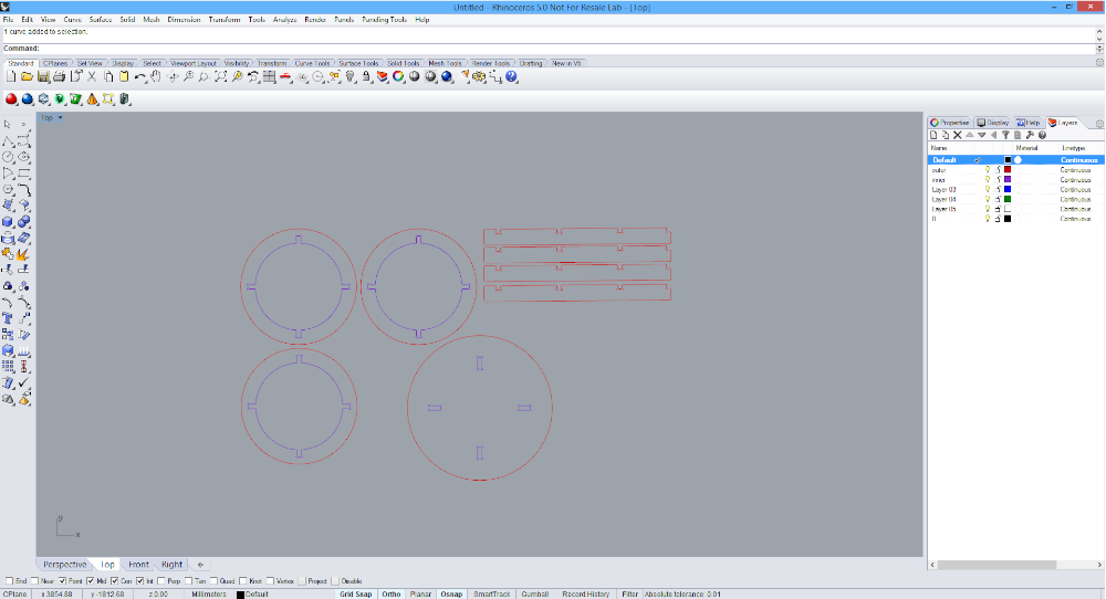
When is everything set in Rhino, exporting is again needed to .dxf file but with the another name and we also need to make sure that we don’t open that file again because the lines might got detached.
Rhino 3D
I can not say a lot for Rhino because I'm not intensive user of it, but like to od some models with him. First time heard about Rhino was 5 years ago when I was applying for architecture student. That is software they are using from first semester until last one. All commands can be runned over the key board easy and fast, values and tipes for each command cand be putted directly or changed in top toolbar. For Rhino is great that he has like Fusion live priview for command that you press, so right away you know is that right command. One thing that I don't like in Rhino 3D is that you can't put dimensions after pressing enter, or maybe you can but didn't get how to do it. After all software is ammazing, has option to have it in four windows with different point of view and for shure that I'll spend ore time to learn about him more.
Now is the fun part…
For this table I decided that I’ll use multiplex with black coat for the material…it looks really nice. Again the important thing to remember is to shut down the machine and the computer in the right way, what unfortunately happened to me, someone before me didn’t do the shutdown correctly so the machine got confused and made the first error on my first try. But that is only great school for me so I got that in mind next time. So…turn on the machine, make shure that all emergency buttons are in 0 position(pulled out), than press buttons RESET-START in that order to turn o the machine, now turn on the computer. Important is to turn on the machine first than the program, not the other way, because the program will not recognize the machine then..
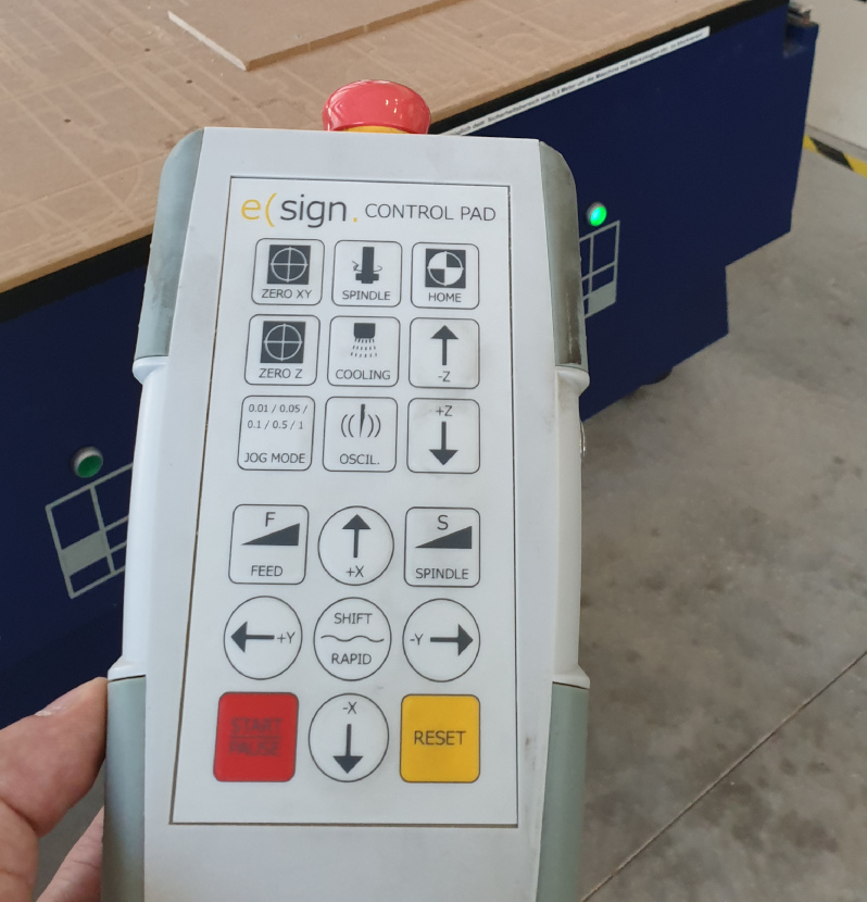
Below is the picture of controller that we use for setting the home and xyz coordinates. First I need to press and hold the silver button and then the home button…silver button is like safety we need to press before any command in case we press something by accident. When machine sets it self to home position we can use faster movement on the axis, now I’ll set the x,y position on corner of the material(it can be set anywhere you want), than press “ZERO XY” button so the machine knows that is the zero position. Than to set up the Z axis I’m using this little thing, forgot how it is called, but it help us to set correct Z axis without touching the table of machine or material.
Now its time to import the .dxf file to the program and set all needed parameters like: safe-z, start-z, final-z, spindle speed, tool and so on. Also to set up witch layer is going to be milled first.
All is set…safety glasses on, ear cover on…let’s check everything before I press START(three major things):
1. Dust cover(needs to be down over the tool)
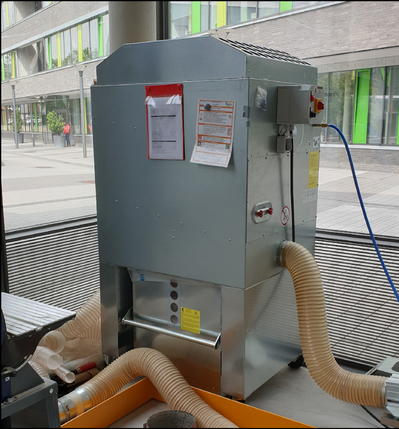
2. Vacuum turned on
3. Ventilation turned on
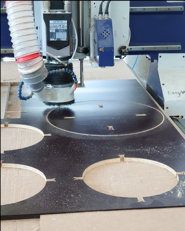
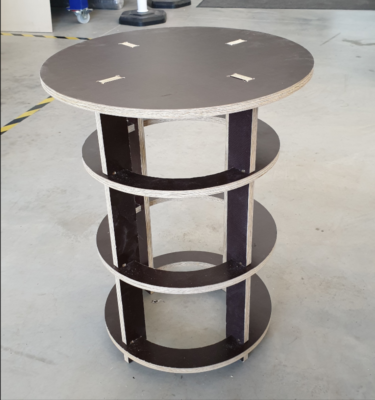
Start the process…all the time eyes needs to be on the machine and controller in the hand. For the end here are some pictures of milling in process and finish assembled table, it looks more than expected.