MECHANICAL DESIGN
15.WEEK
In week 15 and 17 we had the group assignment to design a machine that included mechanics, actuation and automation. This week the focus was on designing the mechanical parts. These should be built and the machine should be able to operate manually.
Therefore I would like to mention at this point that the construction of the cocktail machine would not have been possible without the additional support of Jörg, Ilhan and Benedikt.
IDEA
As an idea we had several machines, but we wanted to build a sustainable machine that could also be used for future events. We wanted it to be something that would represent all the skills learned at the Fab Academy. After some research on the internet we found cocktail machines over and over again - the idea was good and off we go!
We were thinking about the leadership and we just didn’t like it.
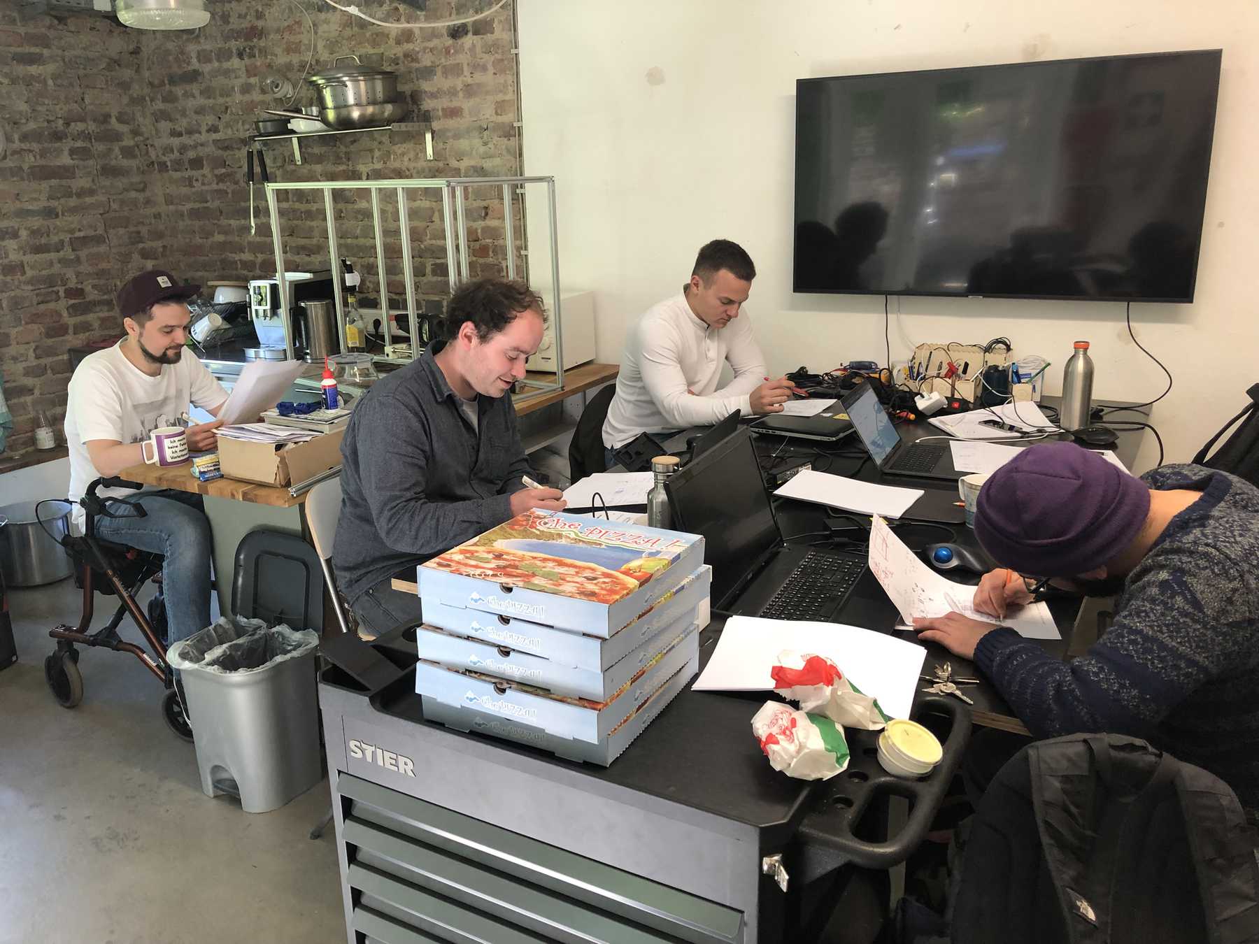
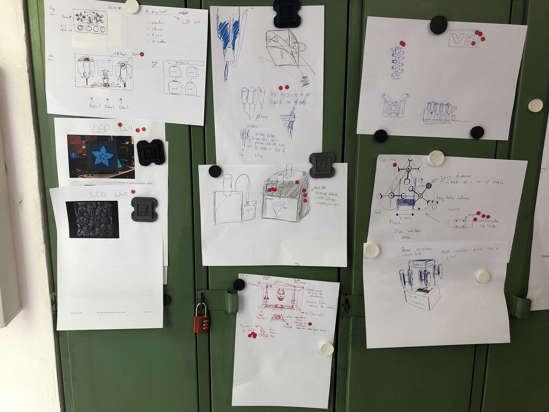
So I invited my friends to come together and look for solutions. We used some creative techniques and ended up with a Wall of Ideas. My beloved dot voting was to decide on the final design by the group. This phase was only interrupted by a delicious pizza.
ASSEMBLING THE FRAME
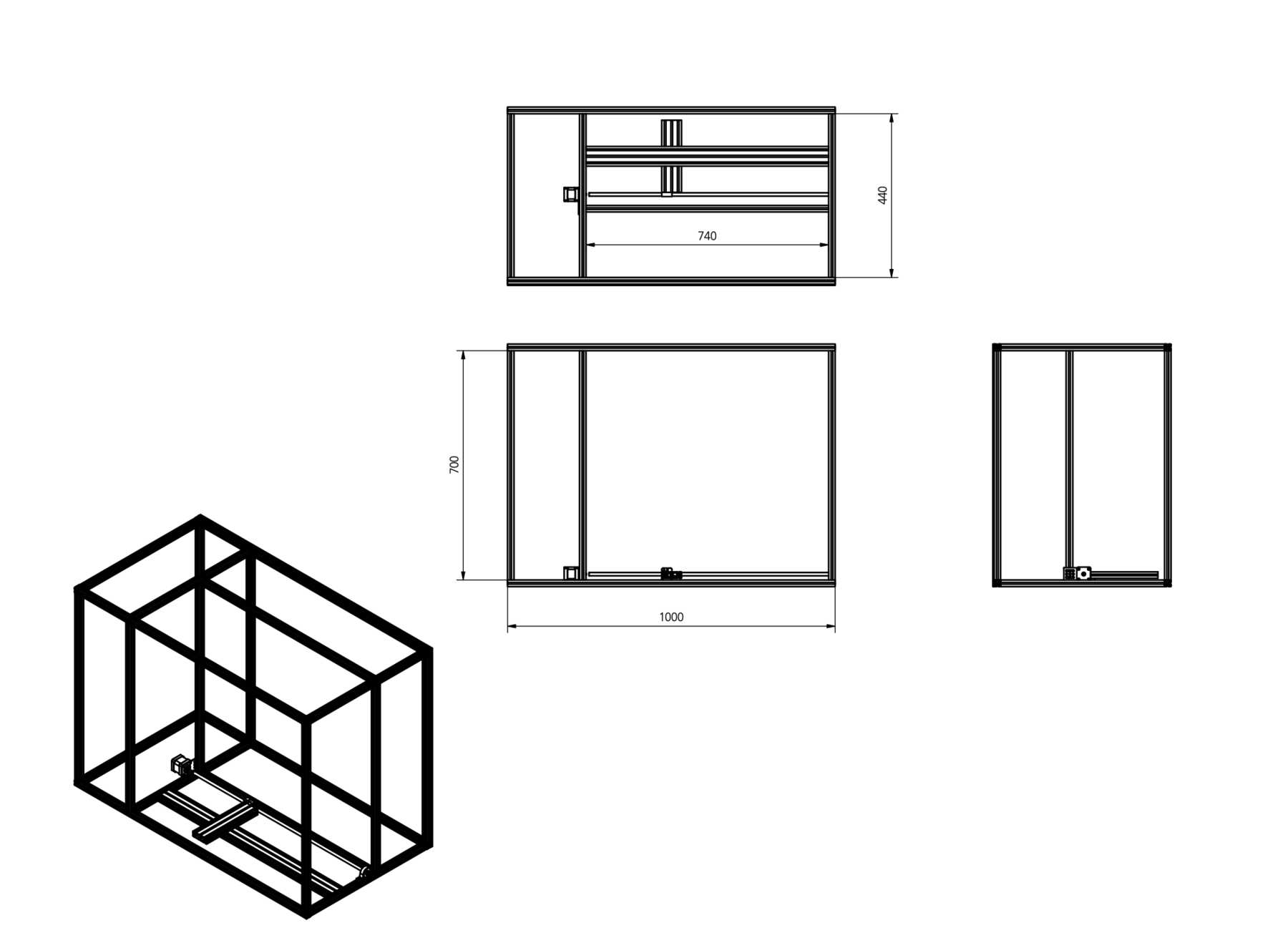
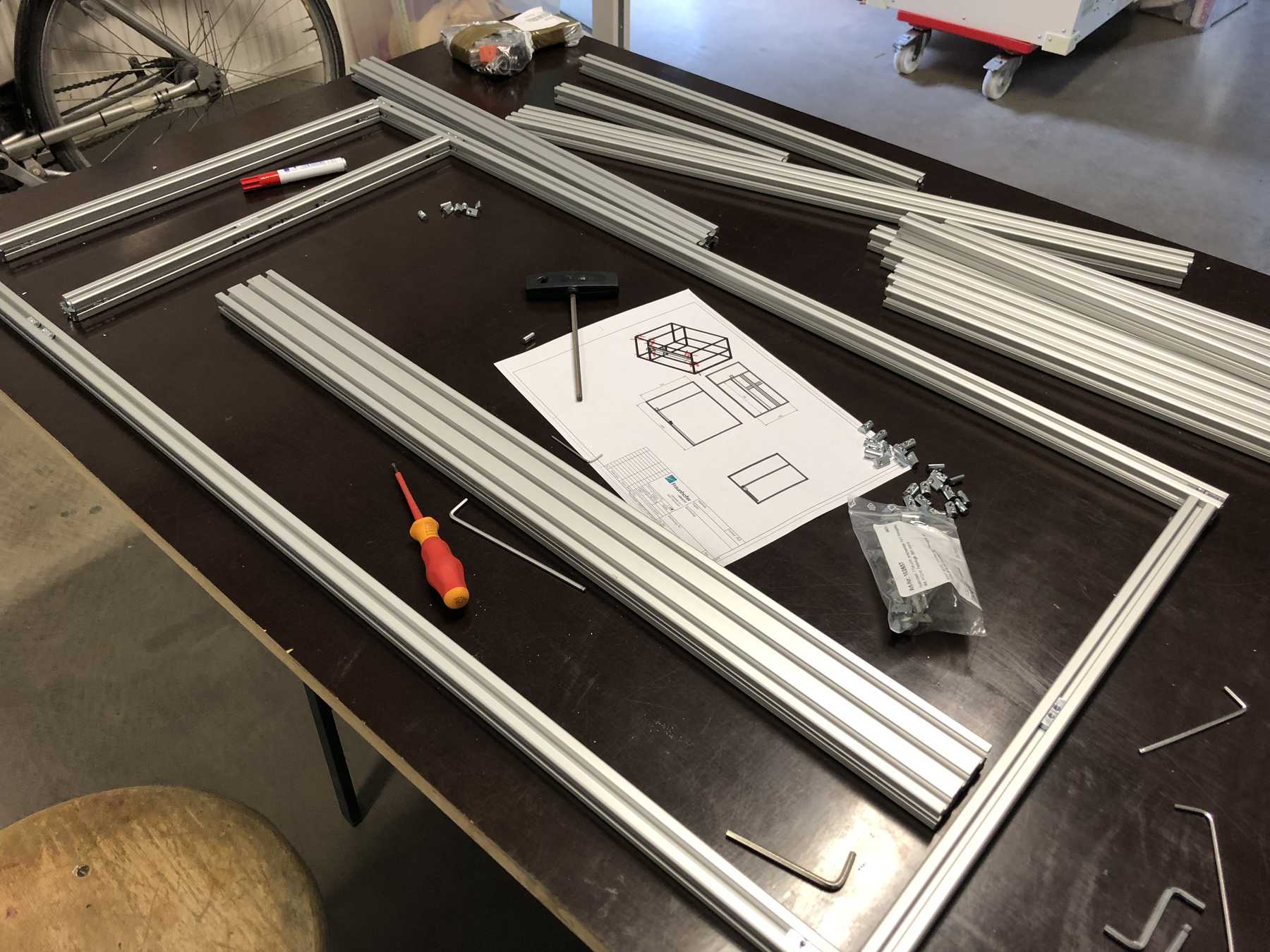
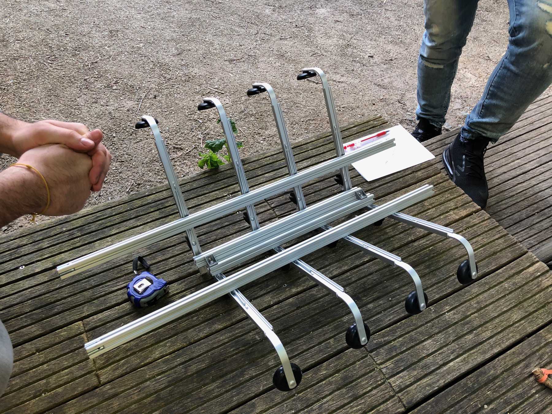
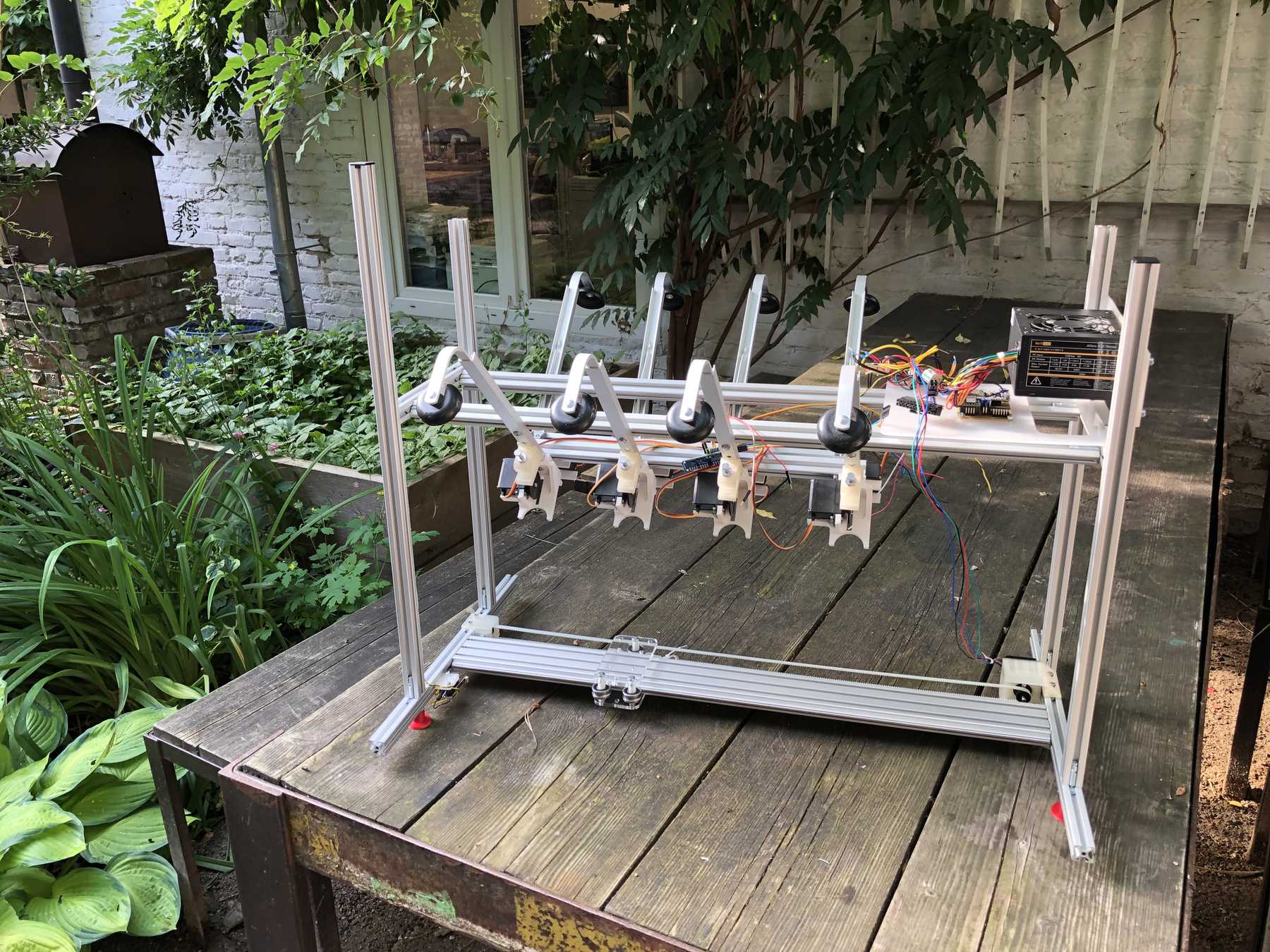
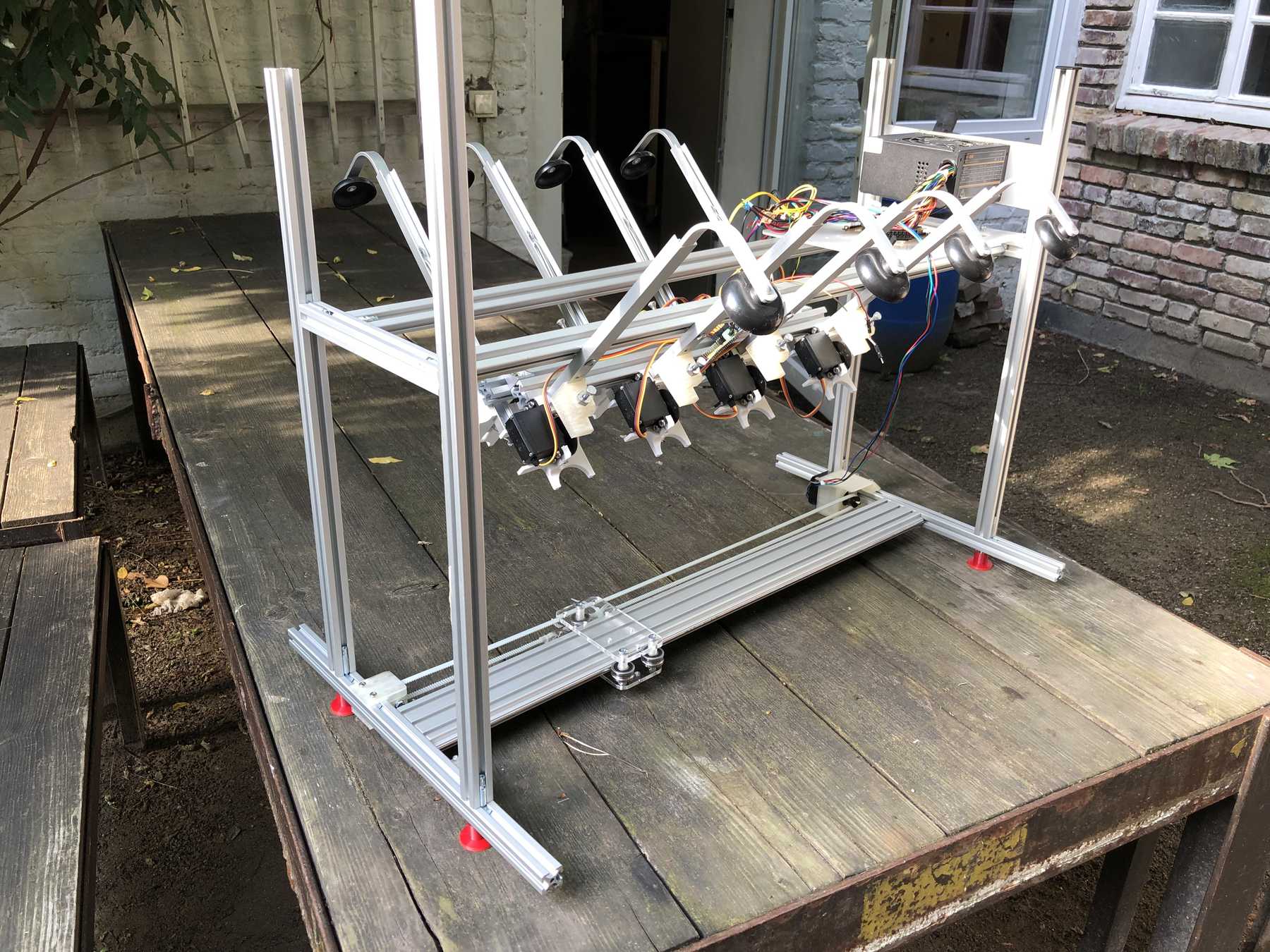
The group has decided: It should be a cocktail machine in the design of a V8 engine. We started with the construction of the profiles and the shortening of individual elements. Since we still don’t know exactly how long the individual profiles will be later, how much space we really need at the end, we left some room.
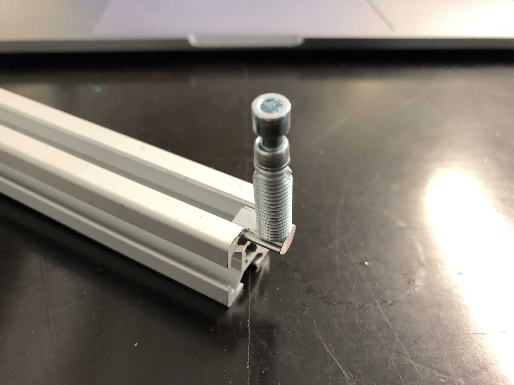
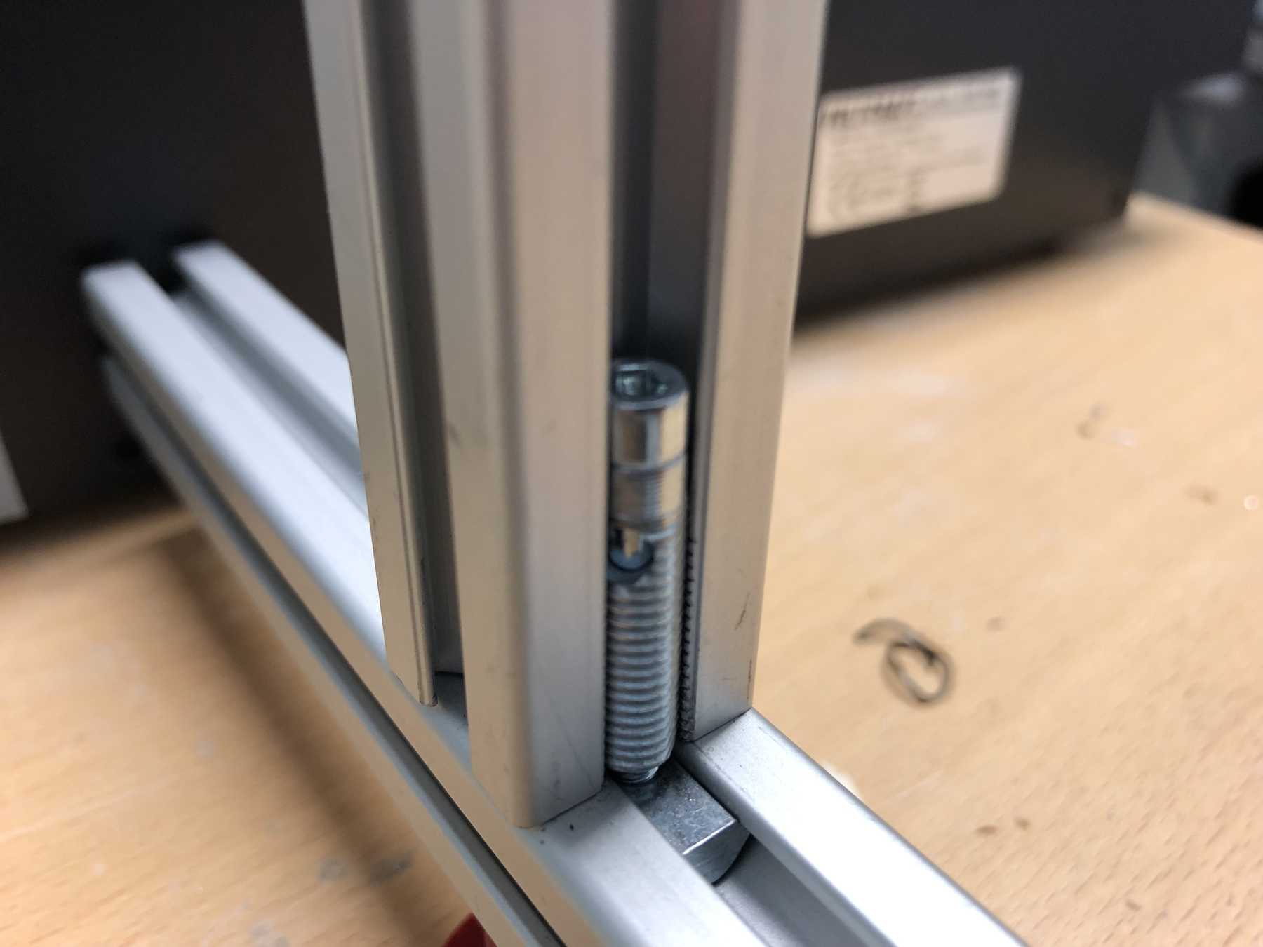
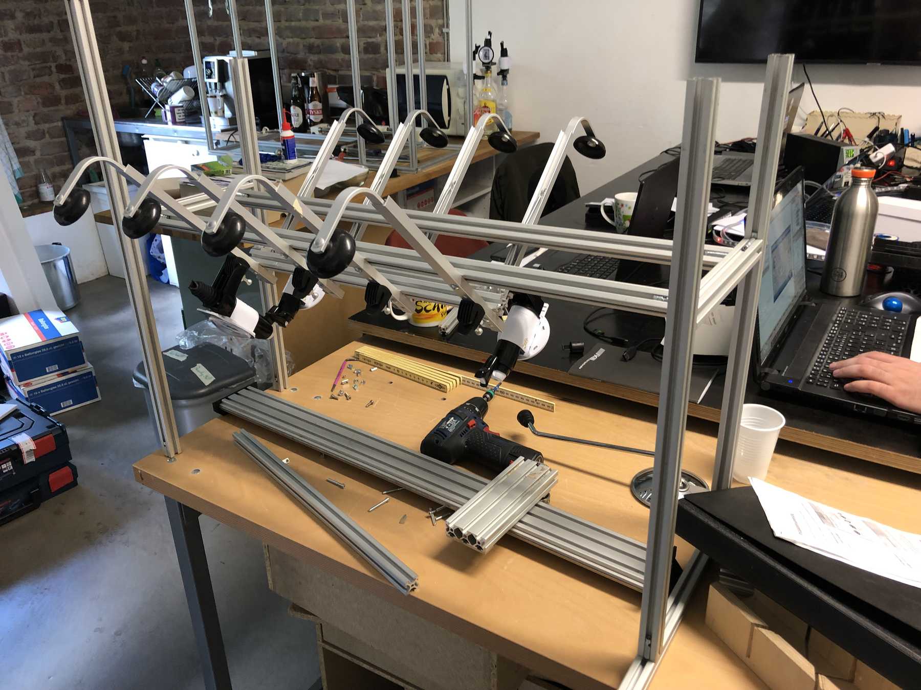
Of course some parts were missing now. The profiles were connected directly via automatic connectors, which are designed to securely connect two profiles. The shell is drilled in self grooving by using a suitable hexagon socket screw key into the profile. The T-nuts are then inserted into the other profile.
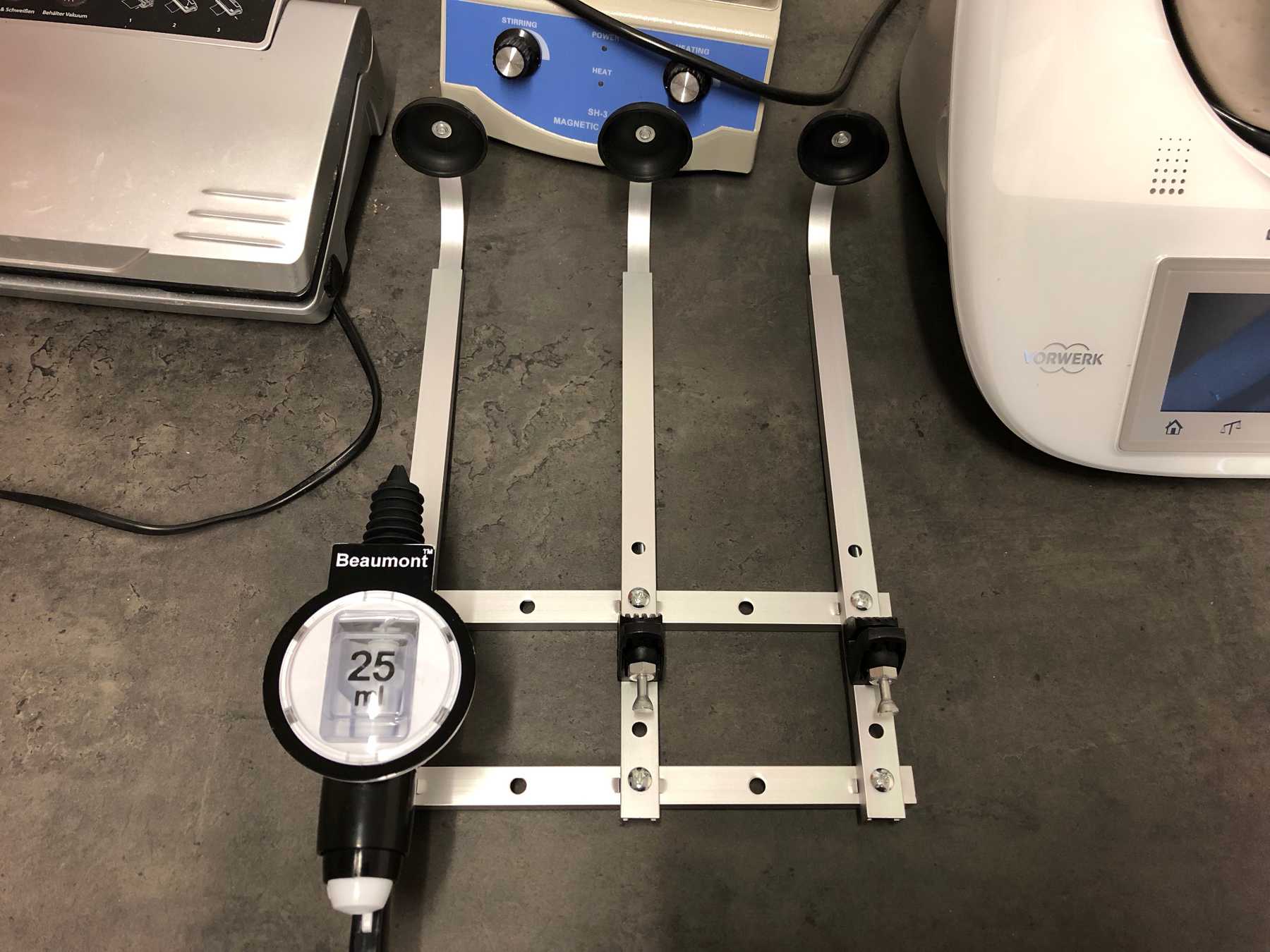
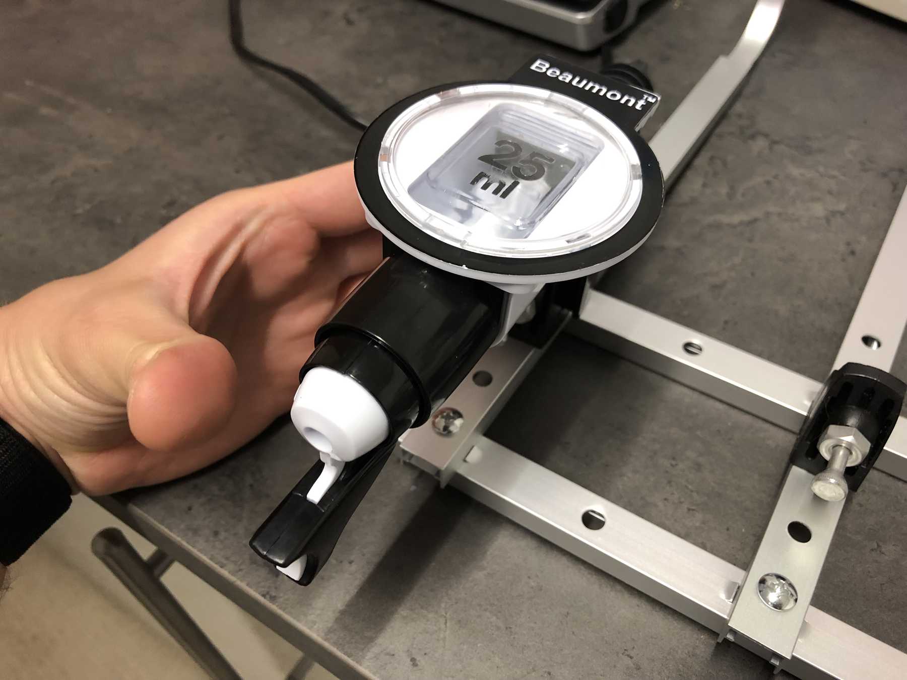
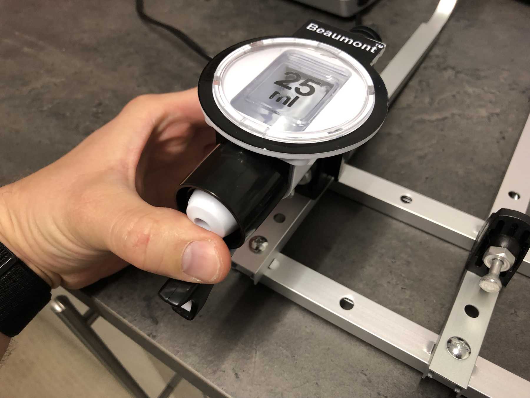
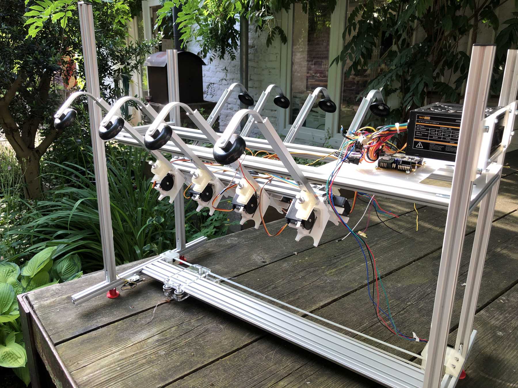
For the bottles we bought the following bottle holders with integrated 25ml dispenser, which has a release mechanism. The bottle holders looked as follows and worked very well. These bottle holders are from the company beaumont and the product has the name 25ml Metrix SL.
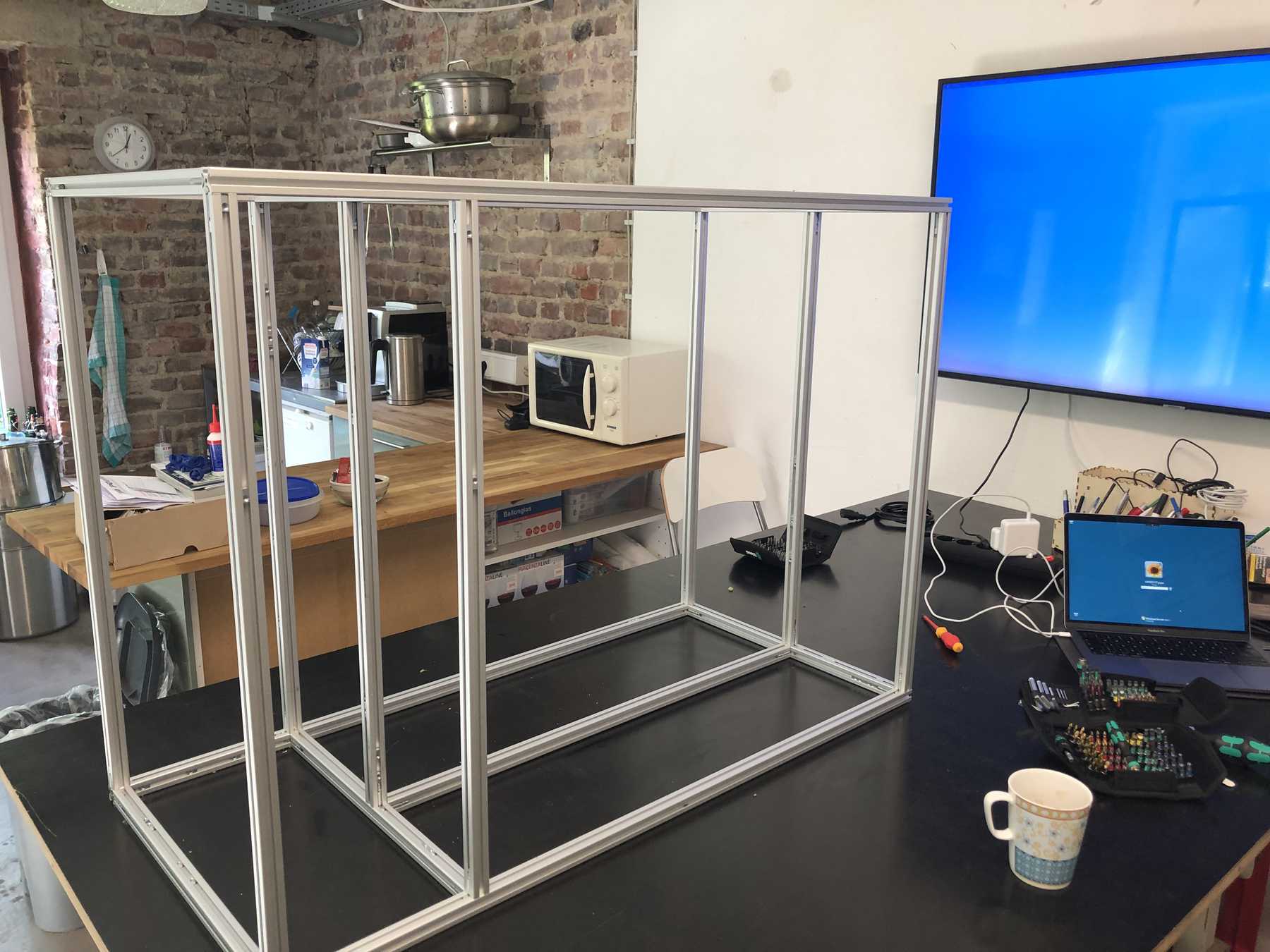
In the meantime the frame has developed. Step by step we came to the following conclusion:
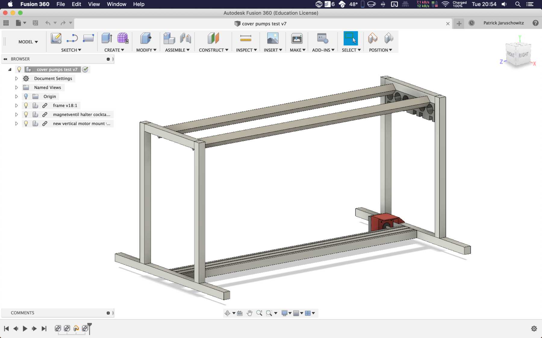
All right, all right. The outer frame stood and further?
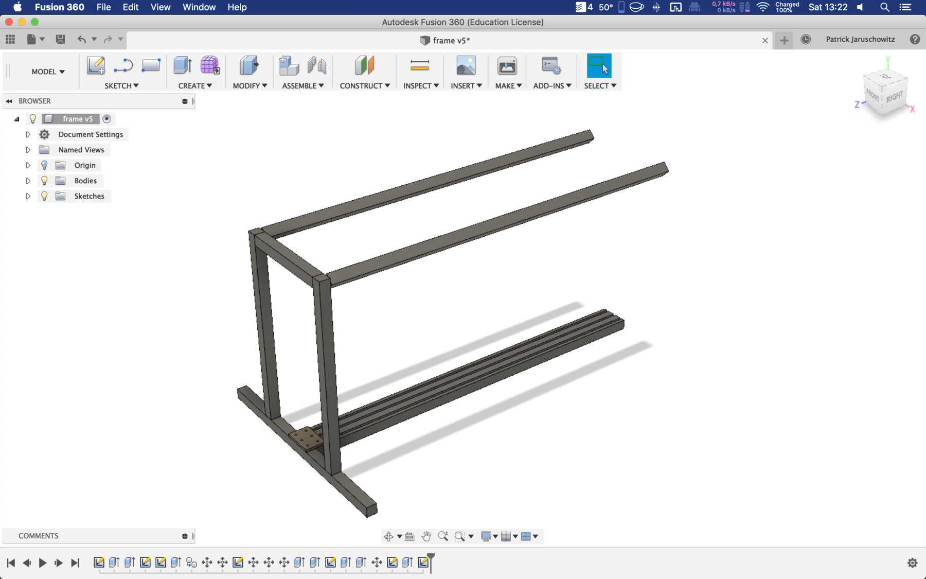
DESIGNING THE MISSING PARTS
Now individual elements had to be optimized so that the entire machine could be improved and function automatically. The following points were missing:
The lower profiles must be on one level.
Feet must be designed.
The holder for the bottles must be turned upside down, so a new design is needed.
The stepper motors must be mounted differently
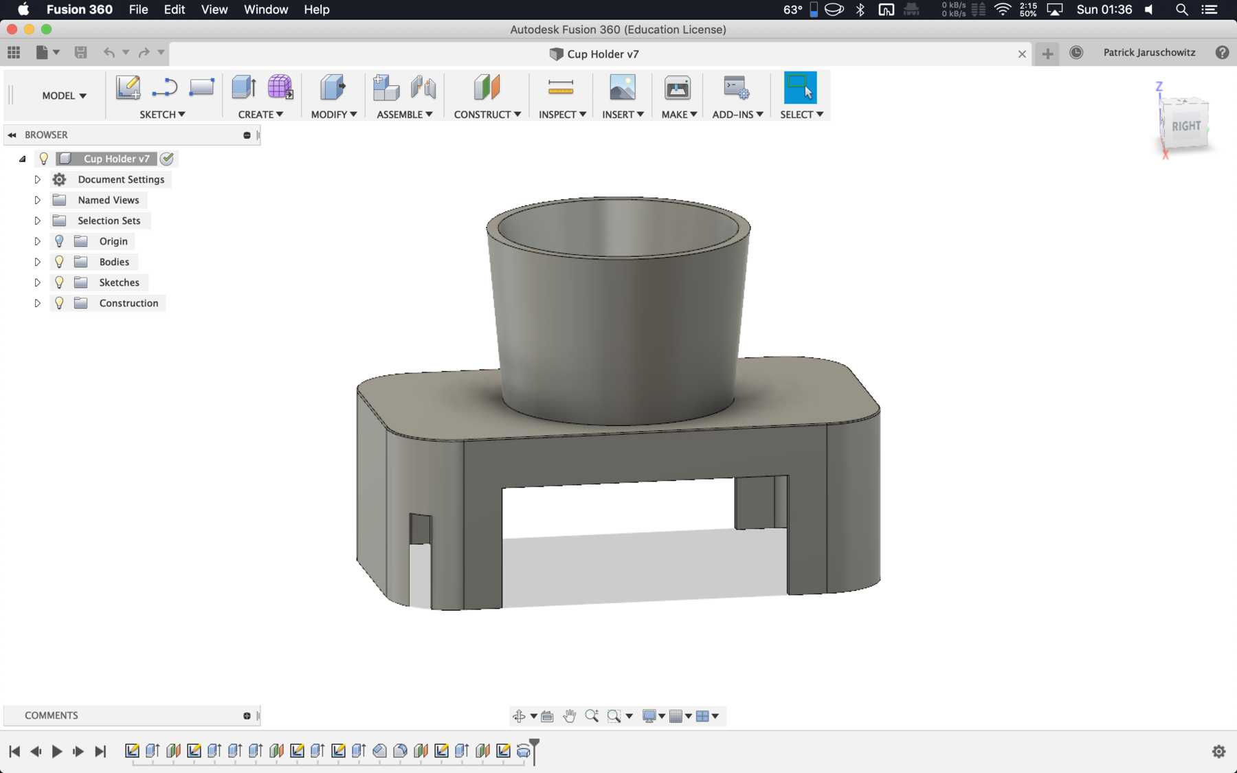
The cup holder must be completely redesigned. Here a modular design is the best solution.
A compartment for the electronics has to be designed.
The dispenser mechanism needs a design for an integration of the servo.
A nice housing must be designed.
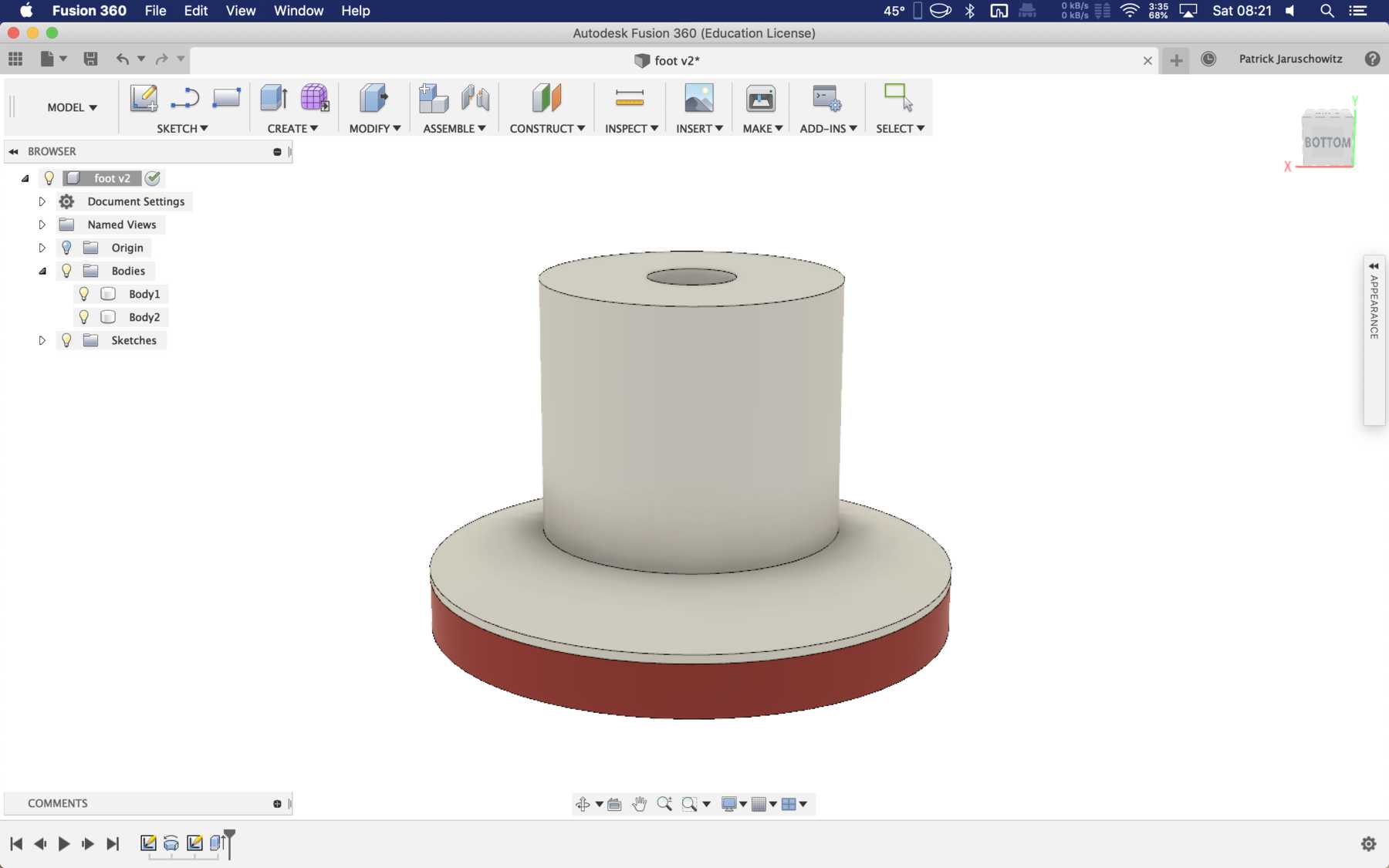
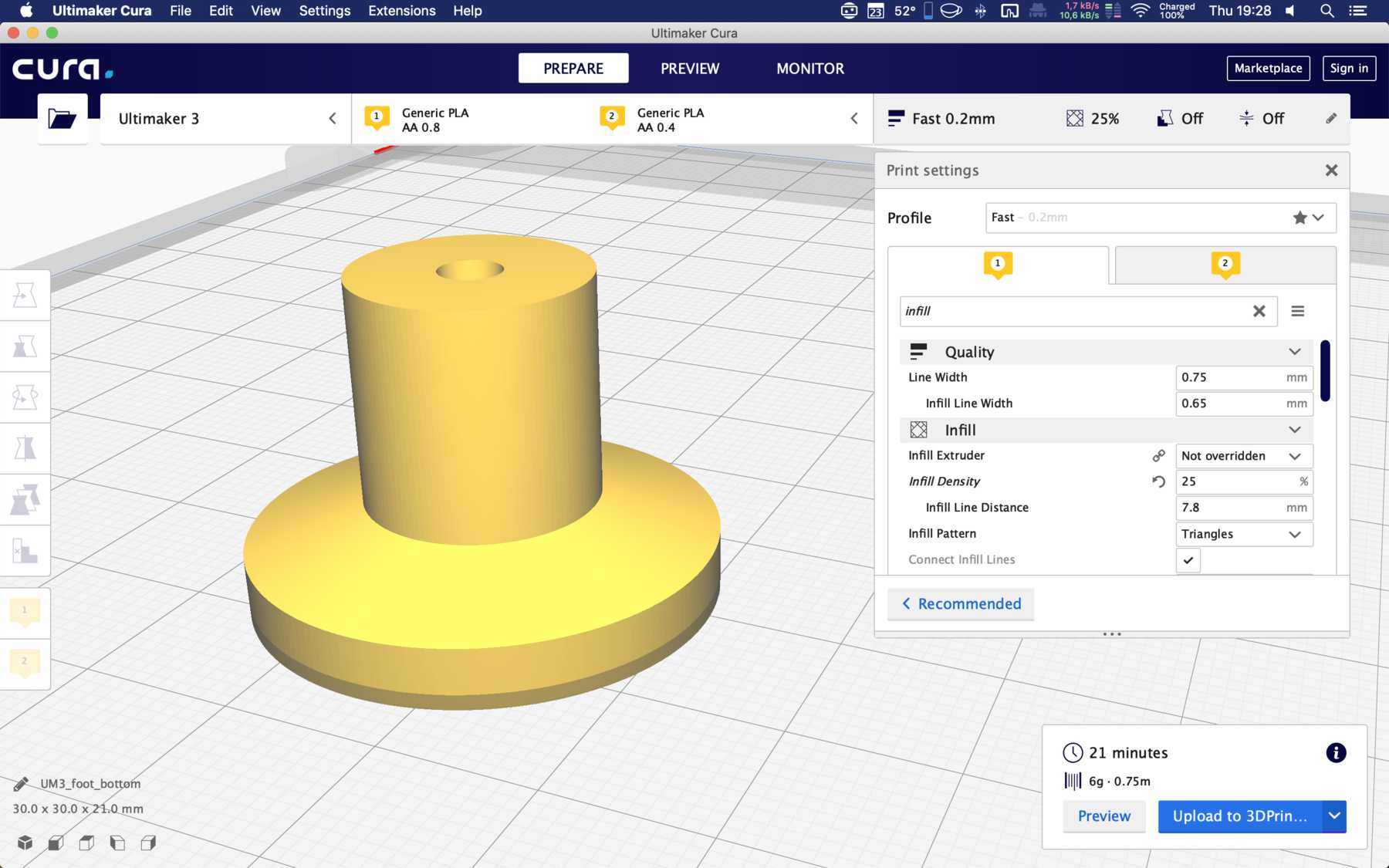
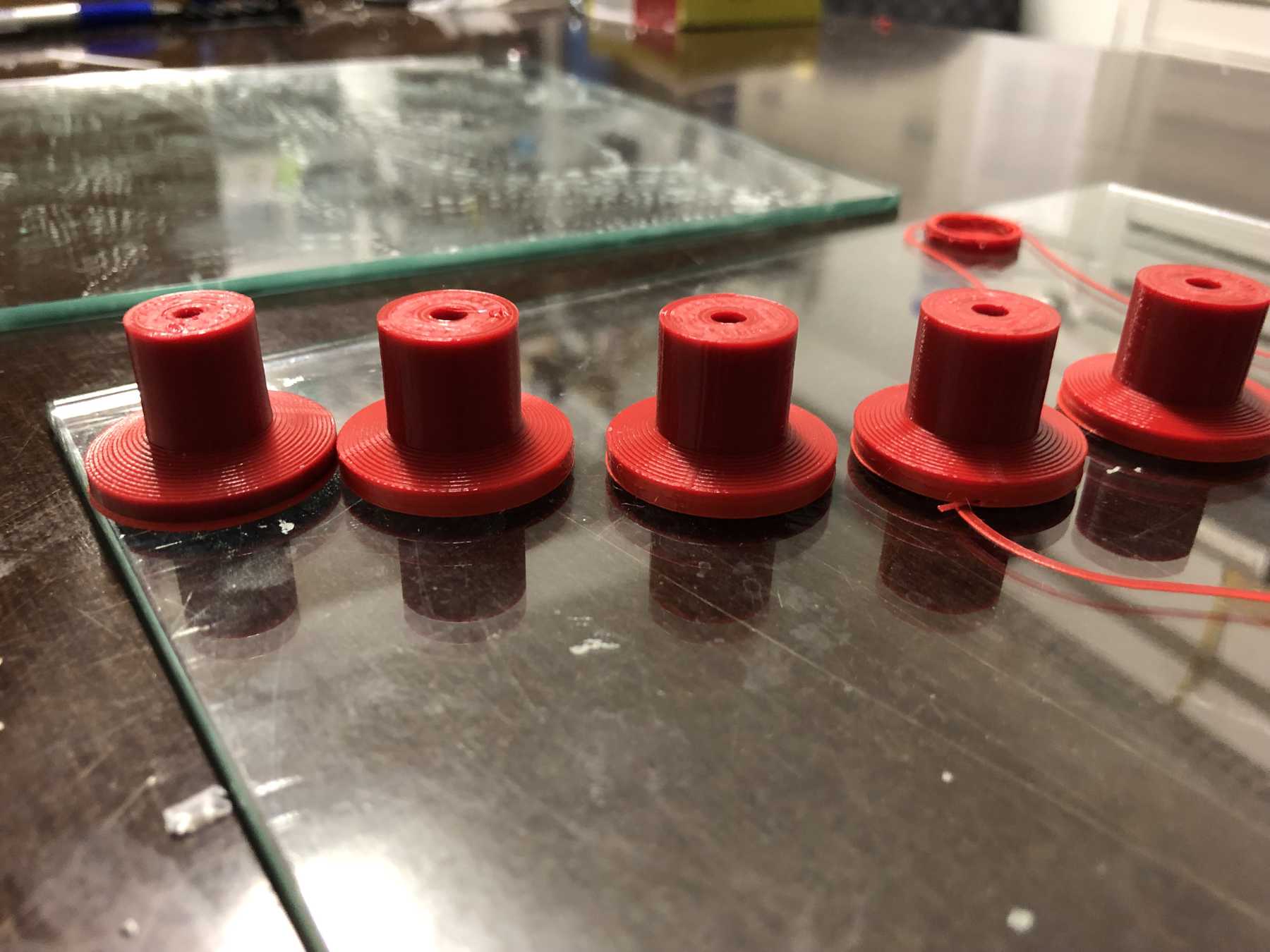
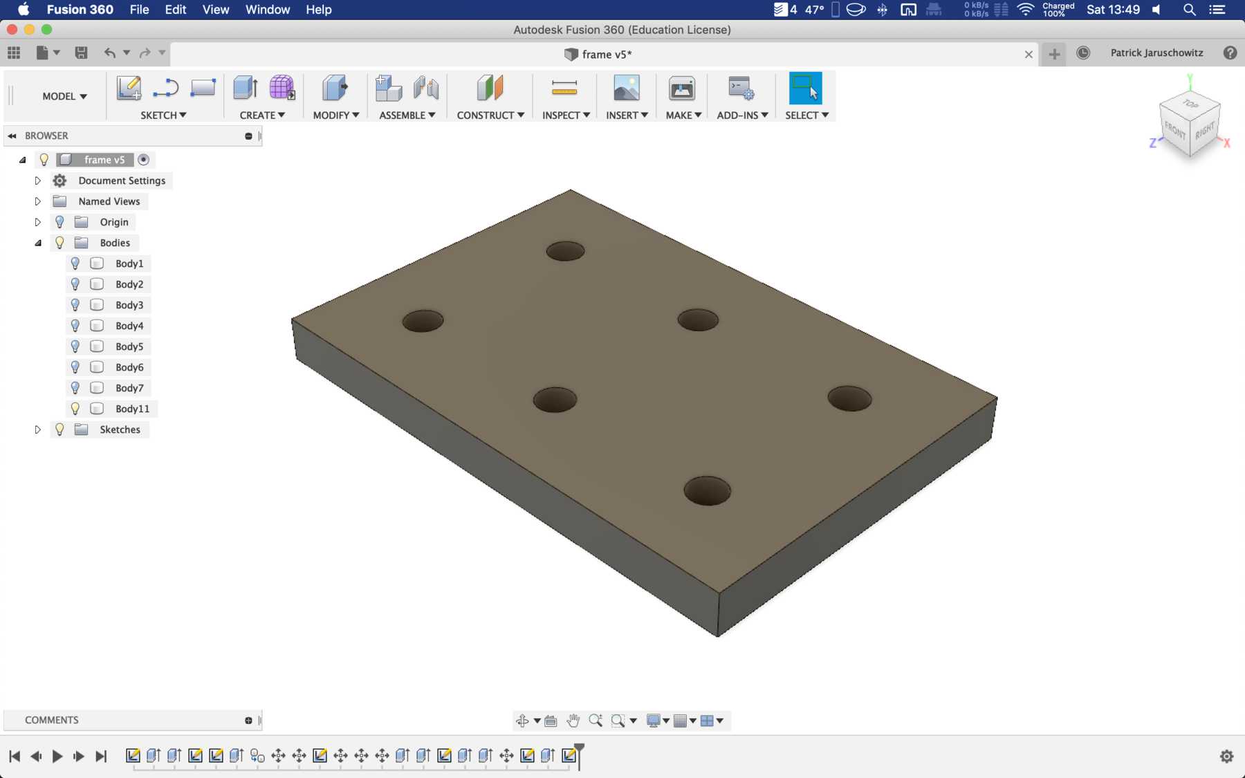
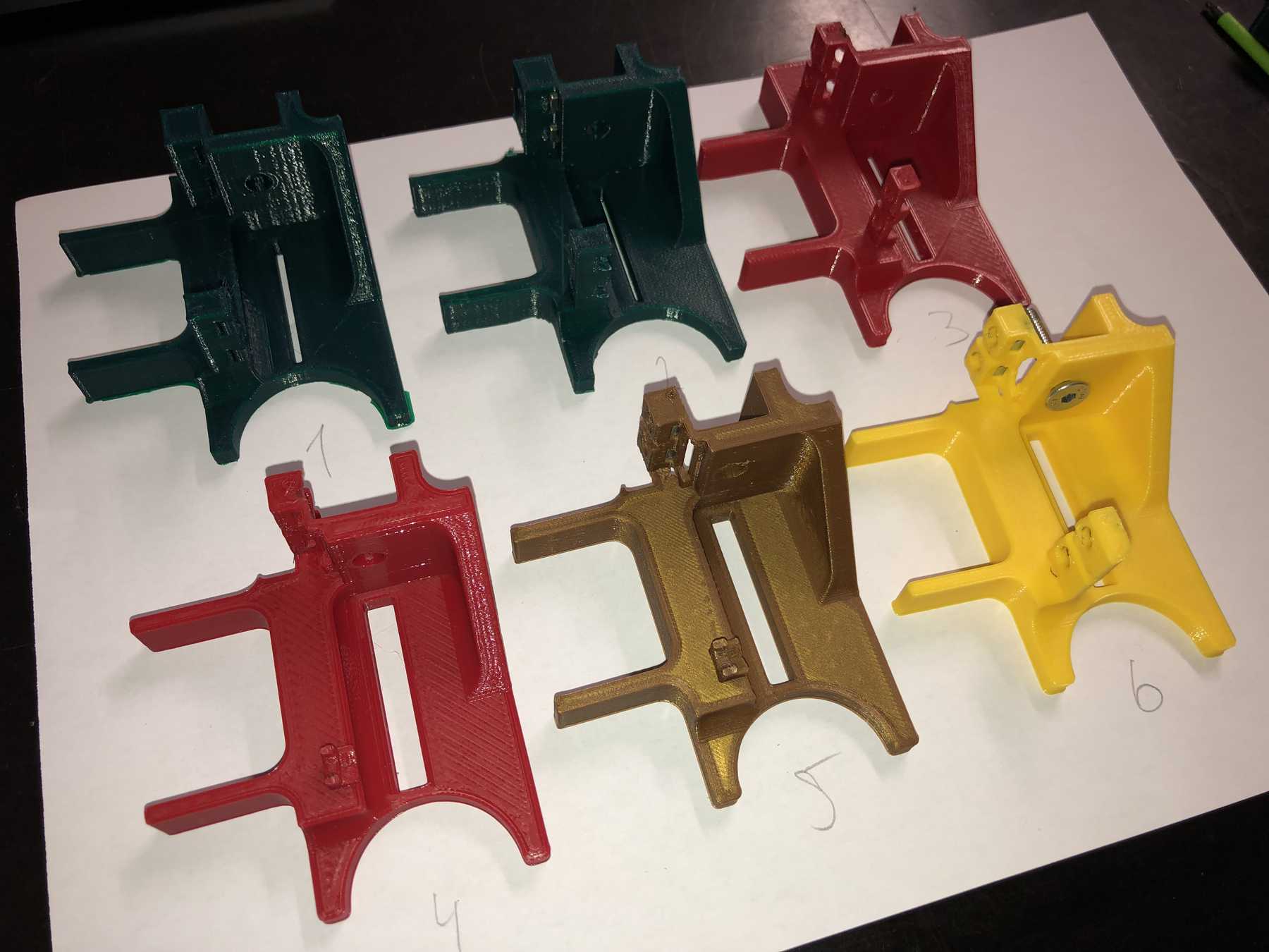
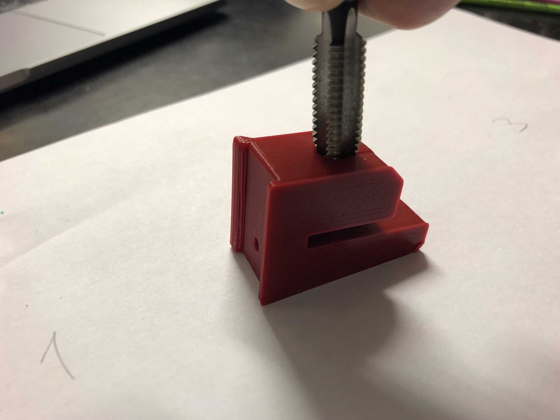
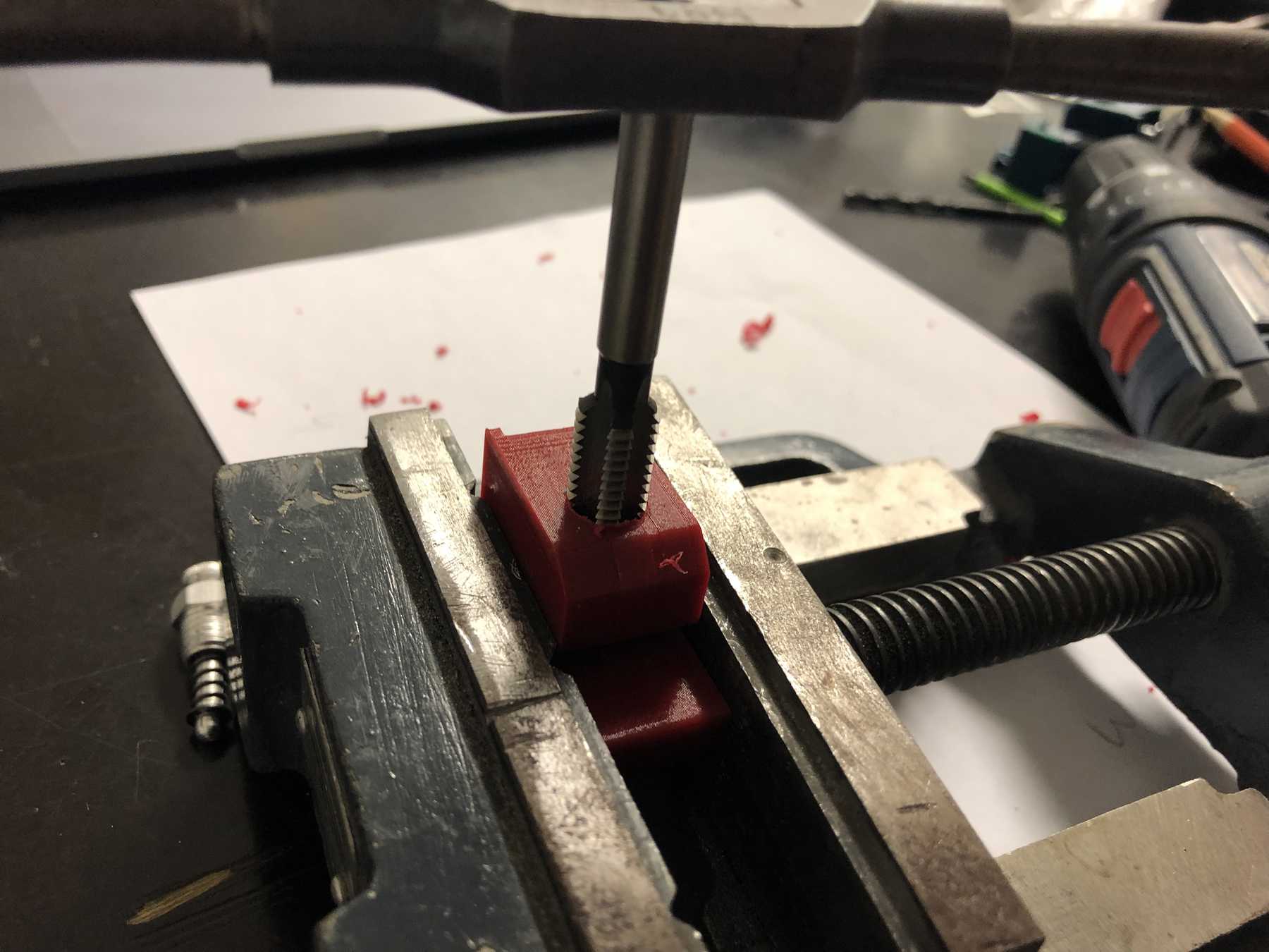
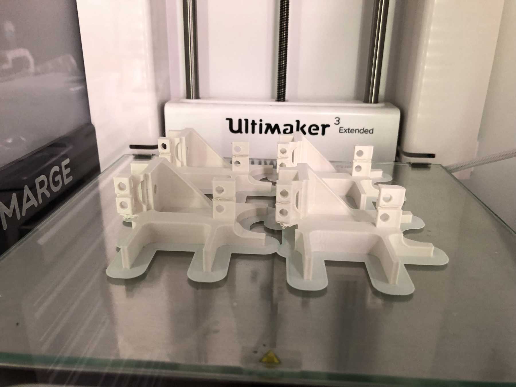
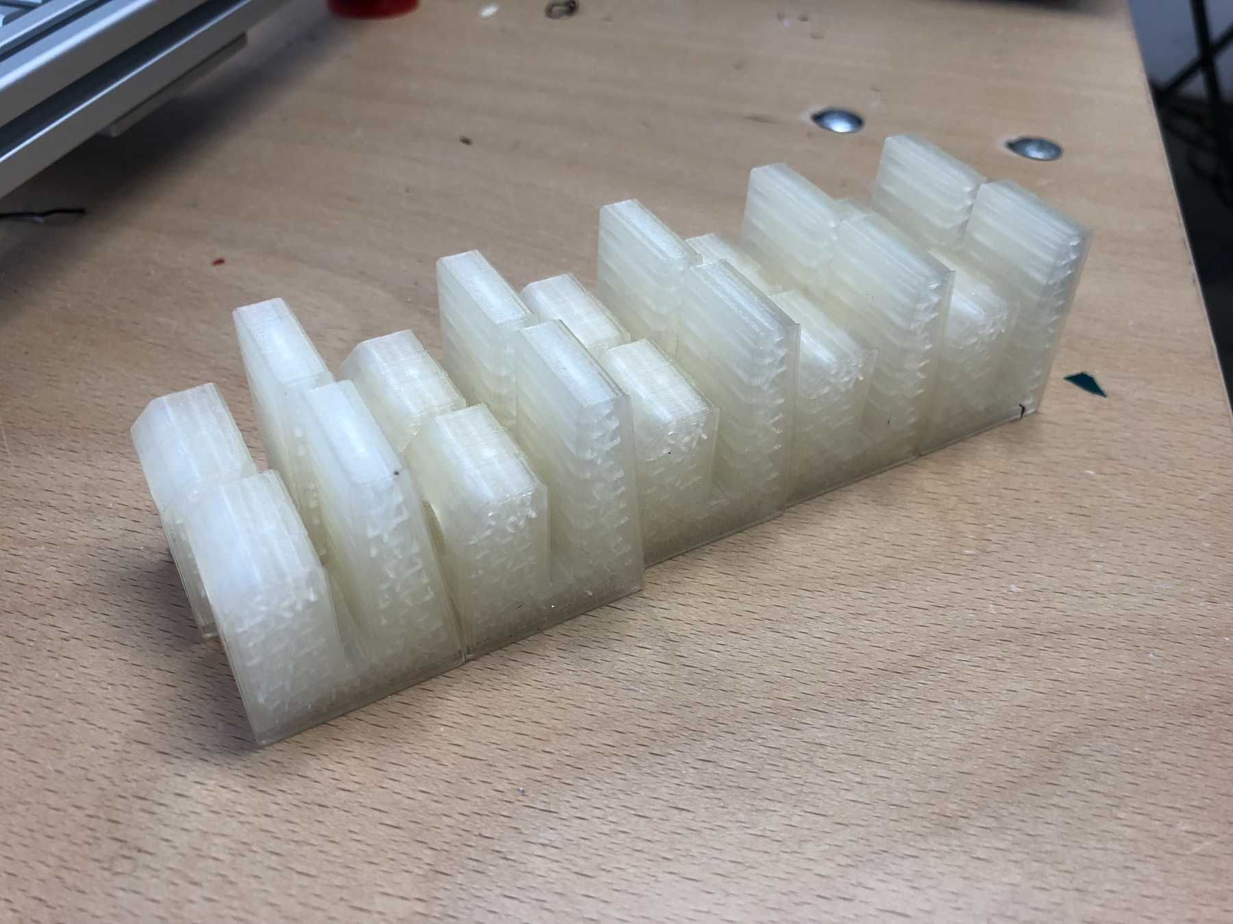
FOOTS FOR THE MACHINE
The stands must be attached to the machine so that there is still space under the carriage plate. I wanted to print two components here. The upper part is made of hard PLA and the lower part of SoftPLA for more grip. The whole design looked like this and the finished parts:
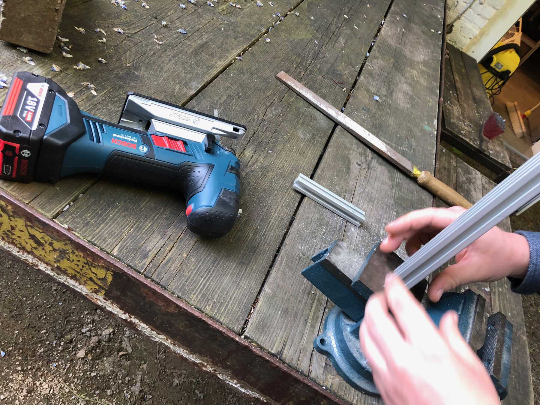
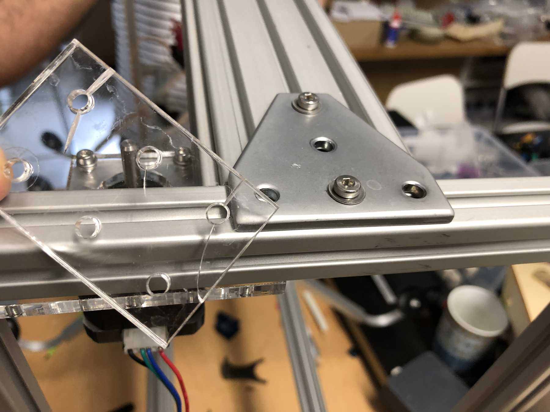
CONNECTING PIECES FOR THE PROFILES
Next, we needed connectors for the profiles to be on one level. For this purpose we have drawn the following design. While screwing together the acrylic glass cracked several times. So we decided to simply take an aluminium rail - and the issue was over:
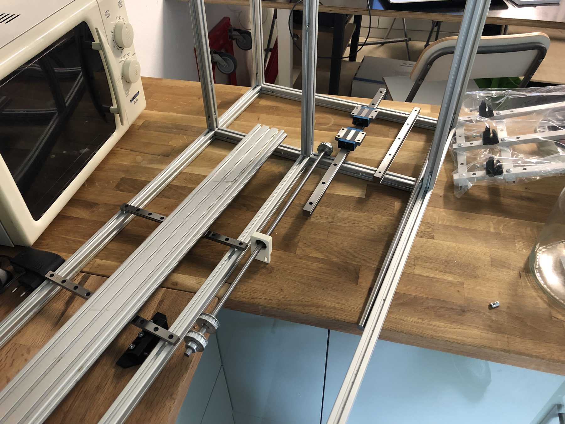
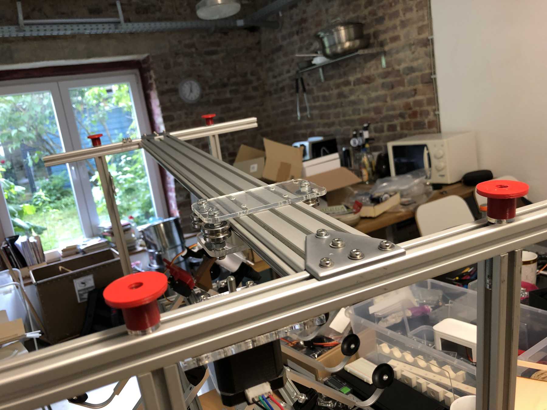
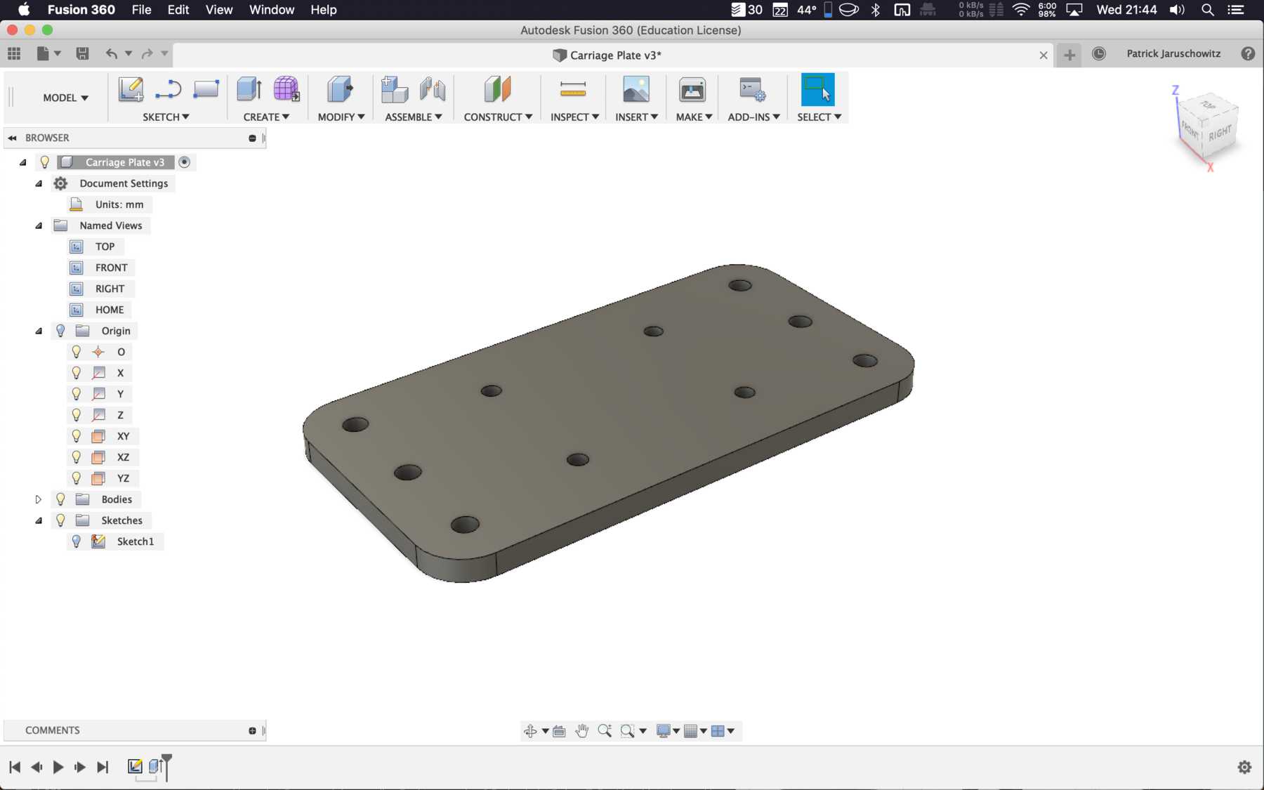
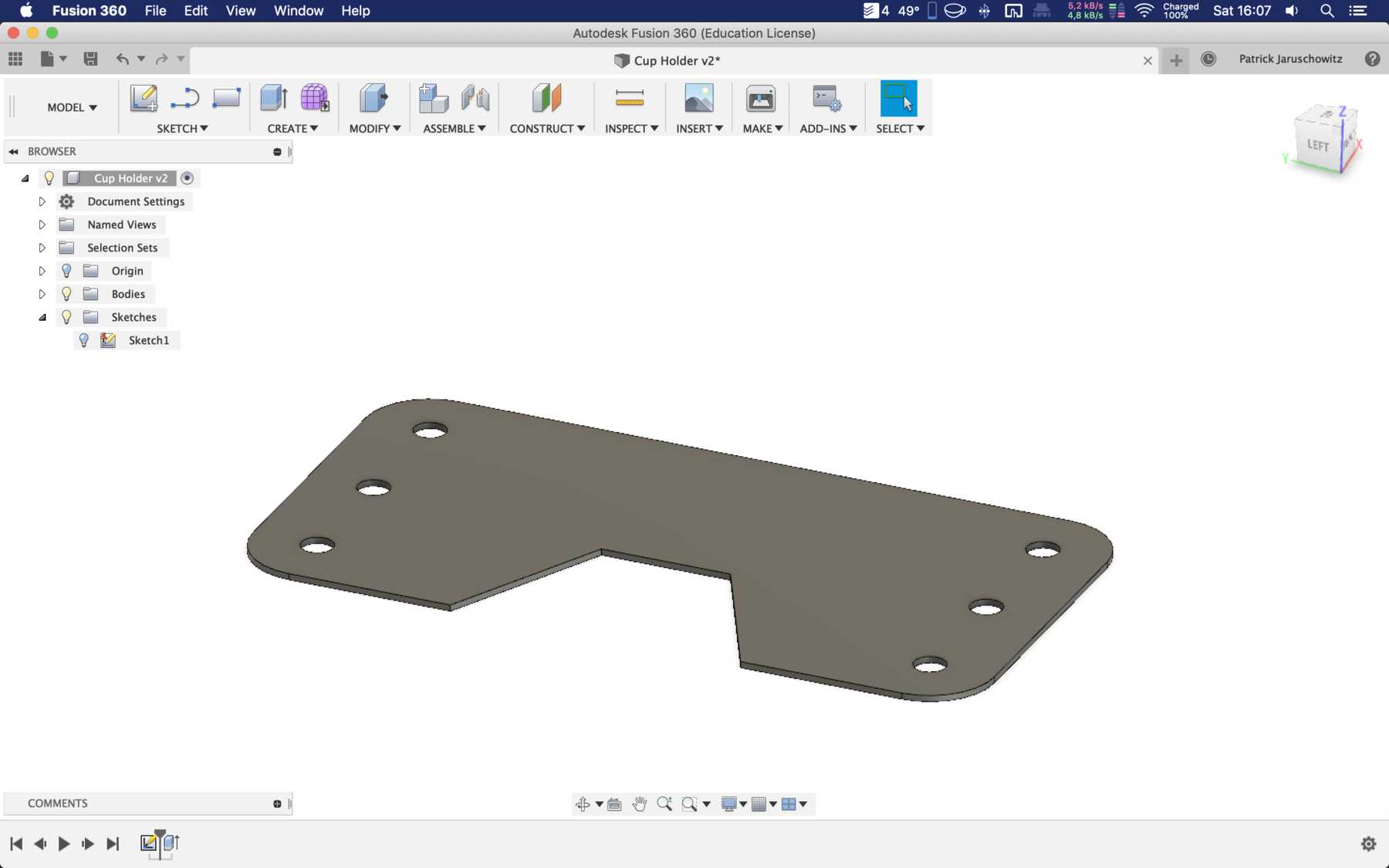
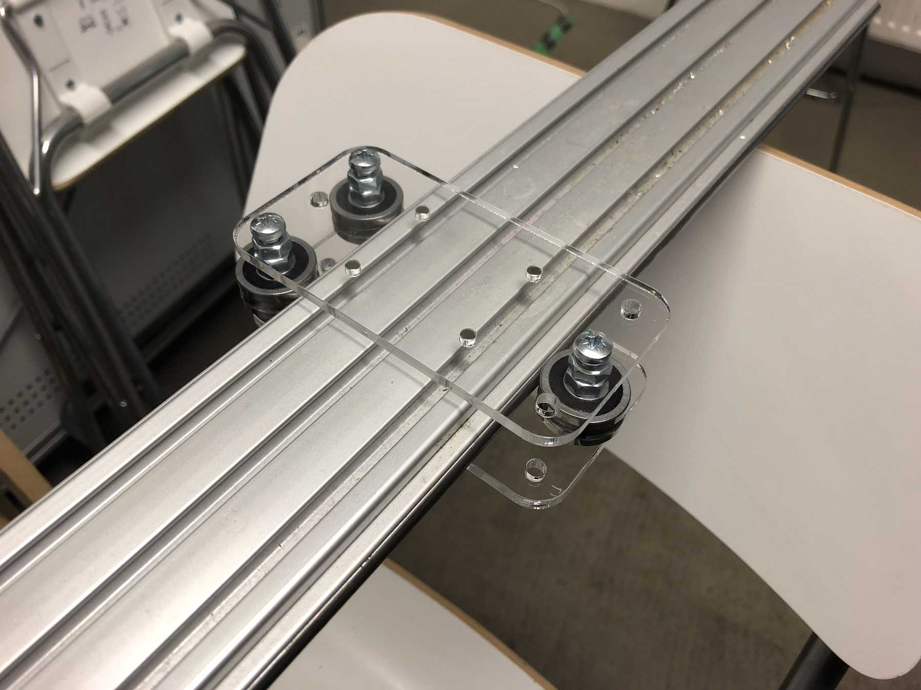
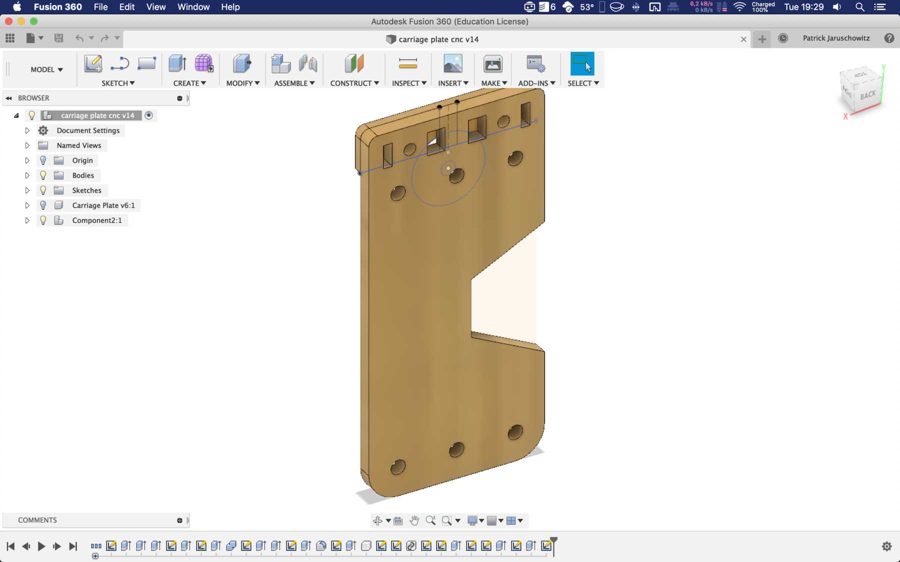
DESIGNING THE CUP HOLDER AND CARRIAGE SYSTEM
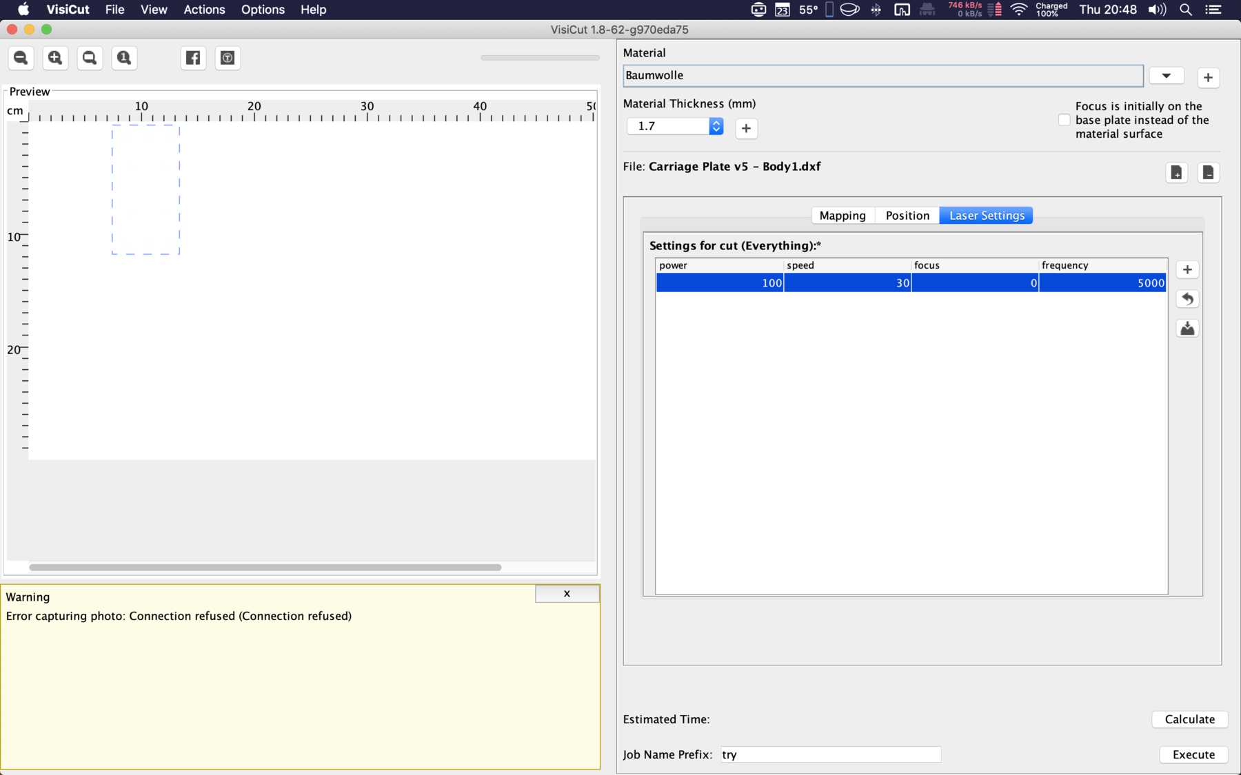
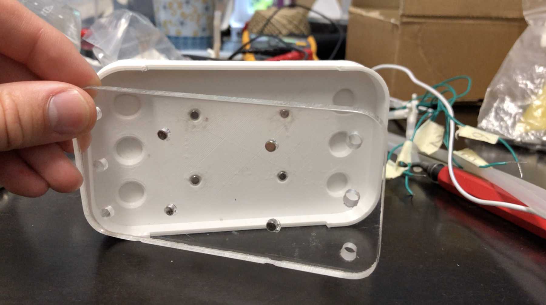
The cup holder should be constructed in such a way that it is modular and can be adjusted to different heights. Ideally with insert pads that would make the whole thing easier. The design was based on rollers that are guided. The carriage system is made of acrylic glass with a laser cutter. There were a few adjustments to the design, as you can see on the pictures. The magnets are embedded and milled so that they fit exactly and are jammed. For future events you can then simply clean the dirty cup holders. At least that’s the idea. First I cut the acrylic glass so that the carrier system looks like this:
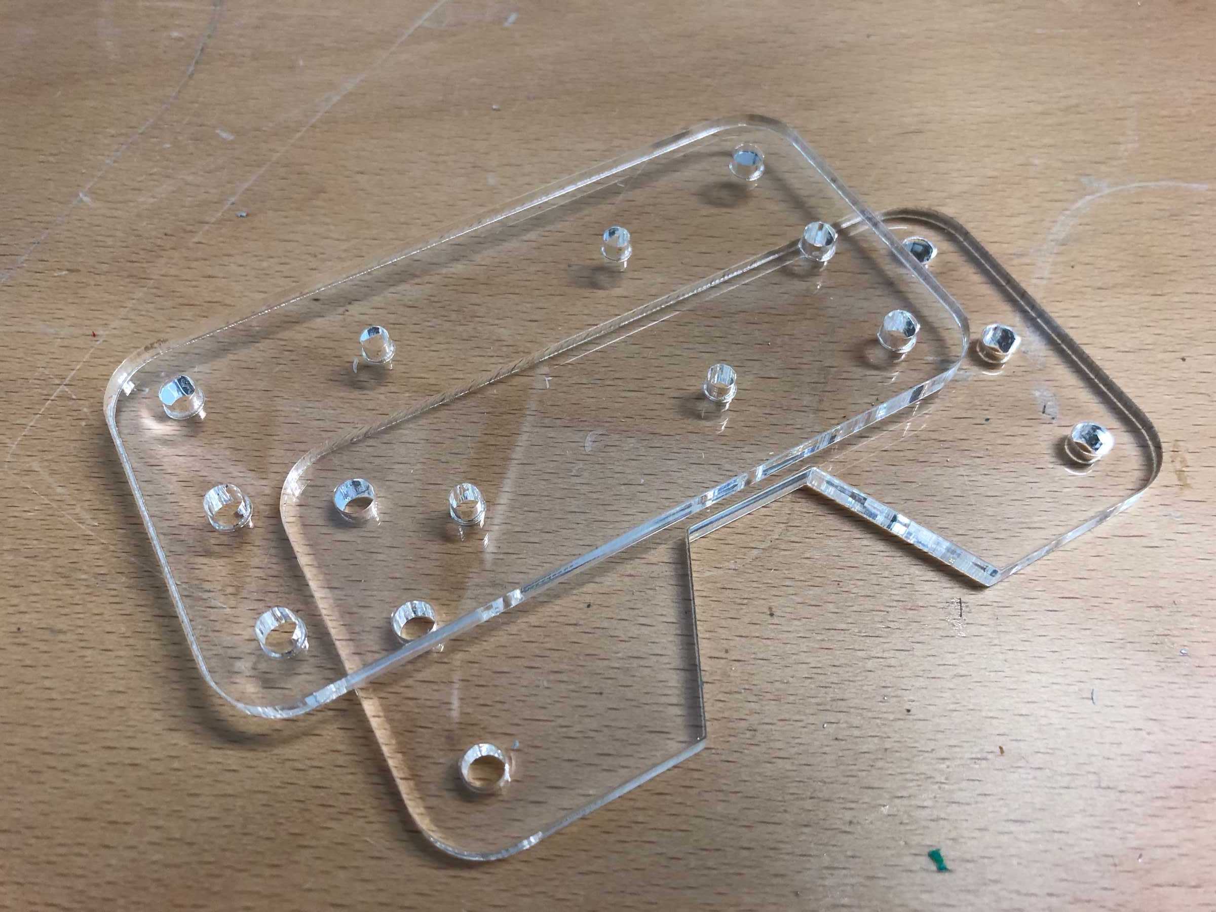
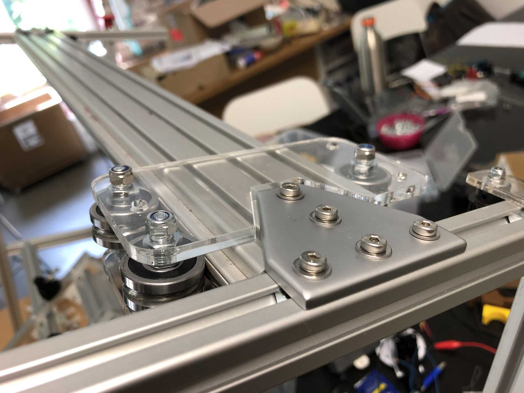
Later we noticed that it didn’t quite work with the belt. For this purpose we changed it as follows:
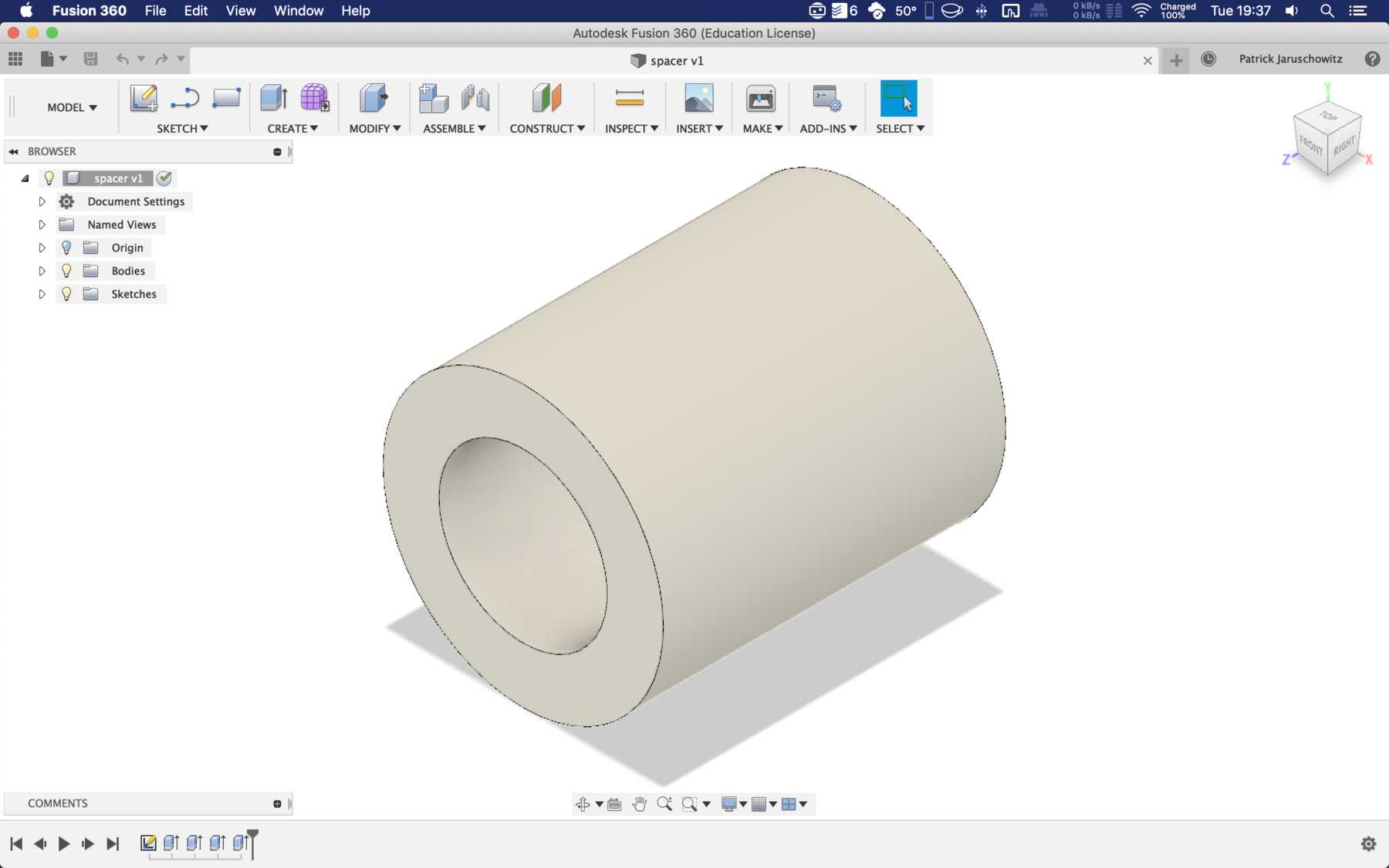
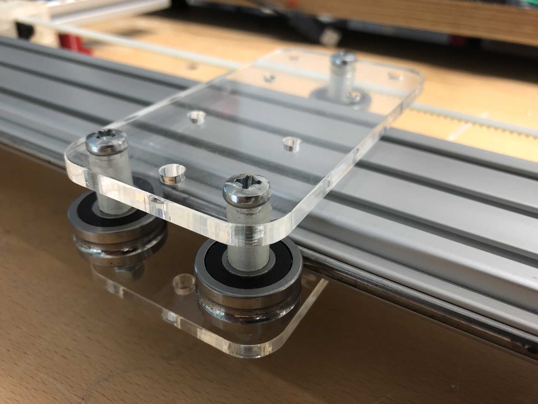
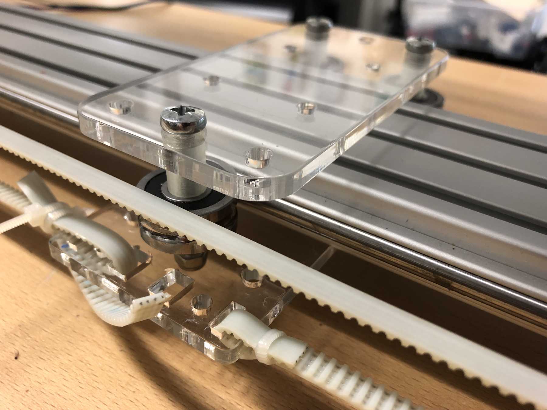
The modular system with cover and support plate is realized by magnets. We also created the spacers ourselves instead of using nuts. And this is how it looks with the lid:
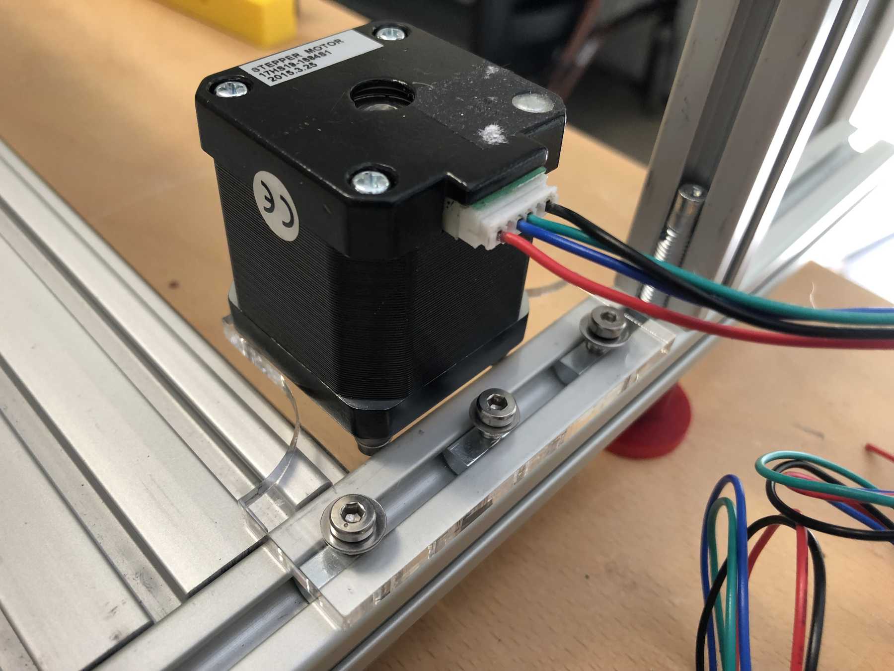
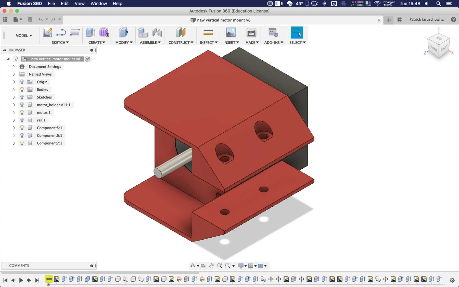
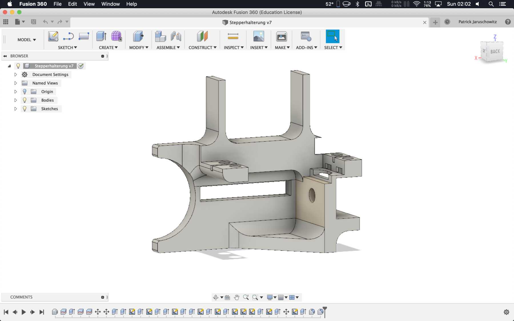
MOUNTING FOR THE STEPER MOTOR
The mounting for the stepper motor was made of 5mm acrylic with the help of the laser cutter. It should be fixed to the profile with three screws and slot nuts.
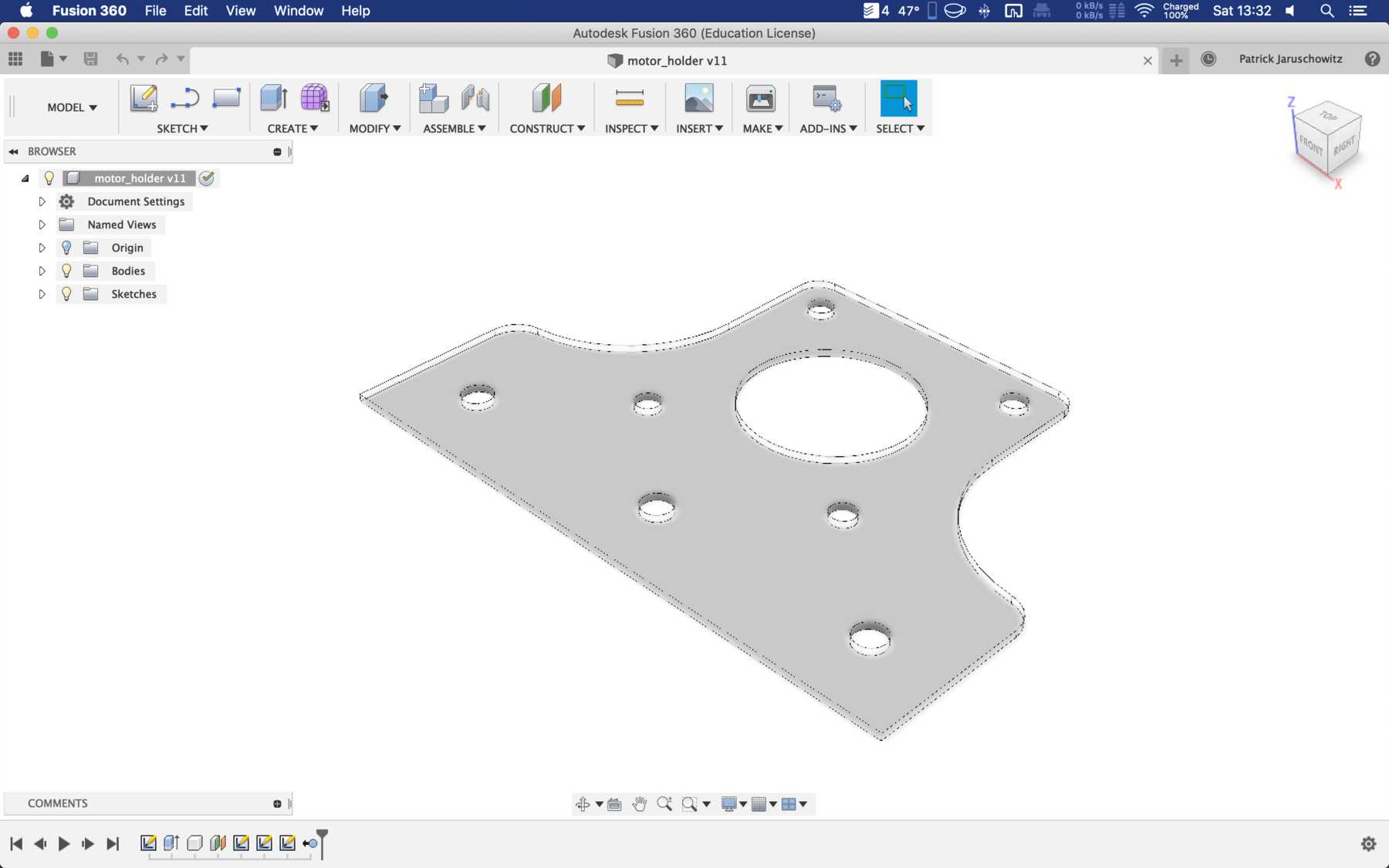
After some iteration the mounting changed:
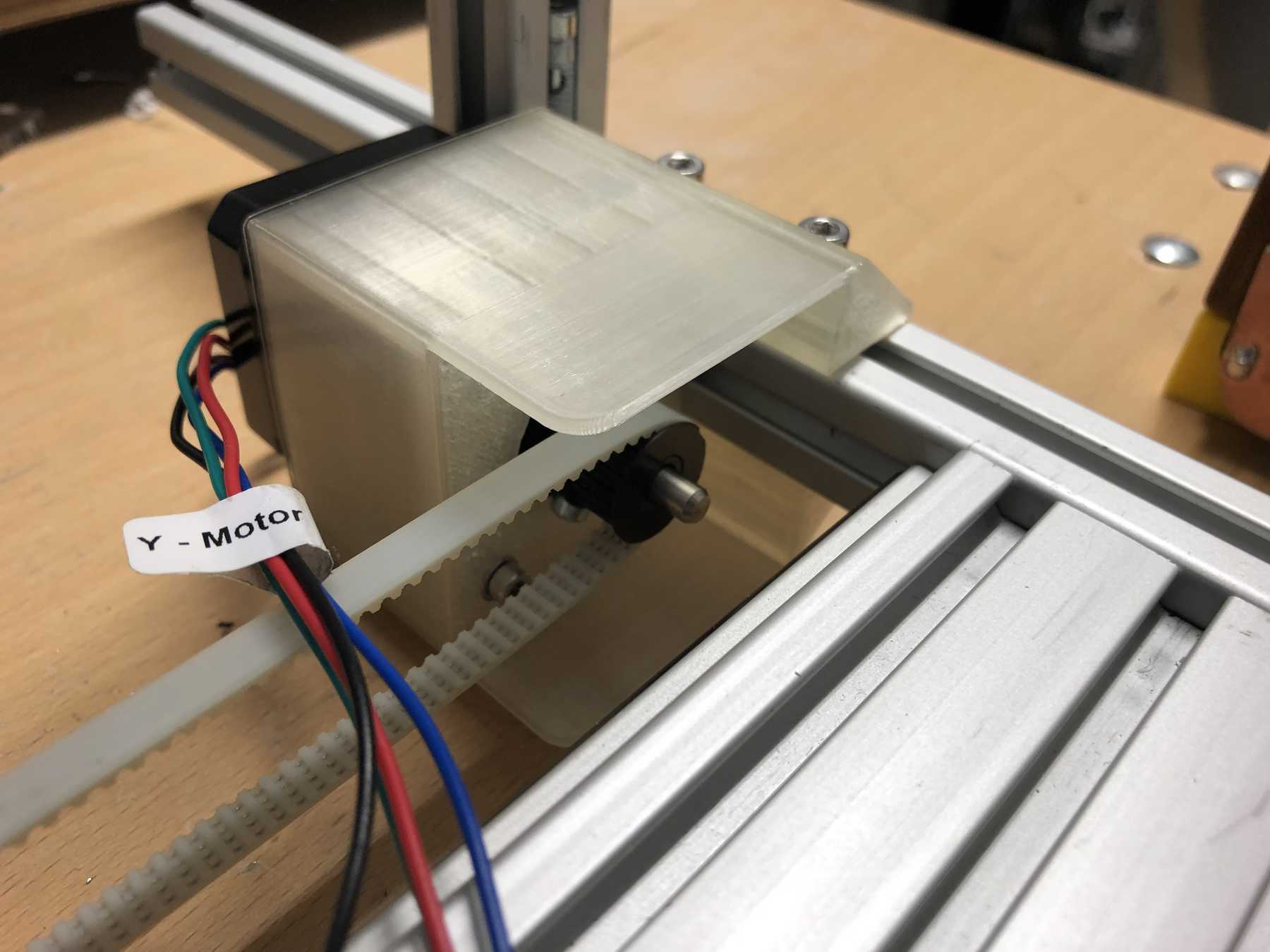
MOUNTING FOR THE BELT
On the other side we needed another mounting for the belt.
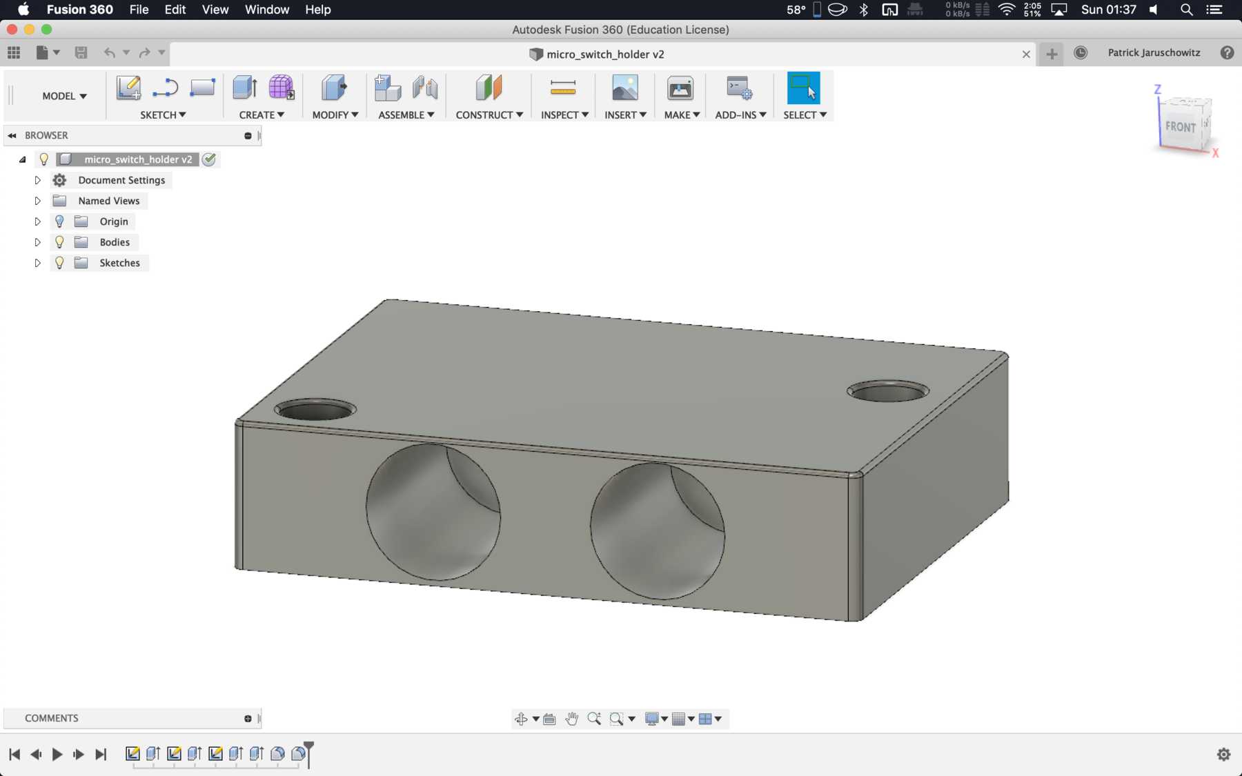
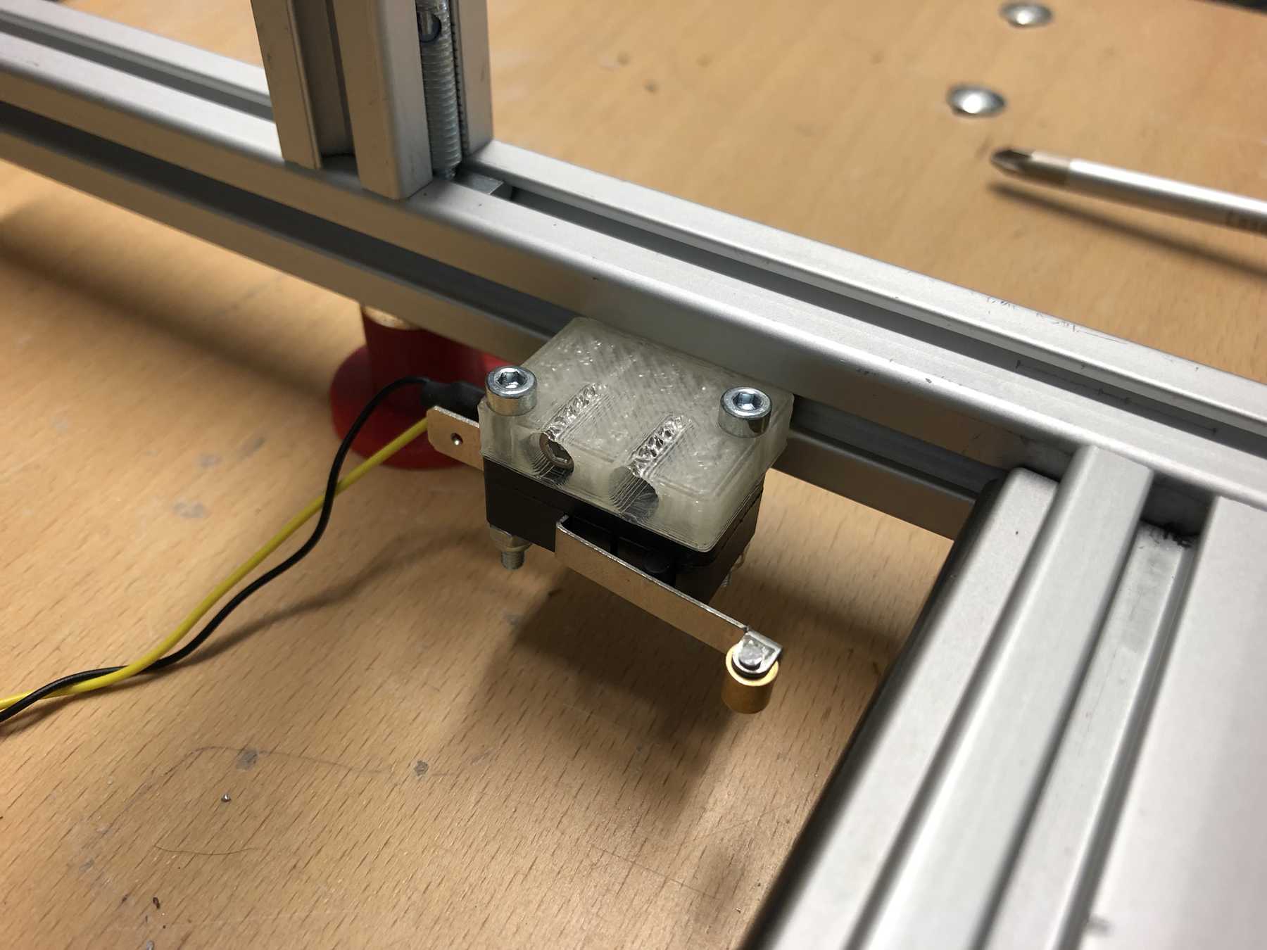
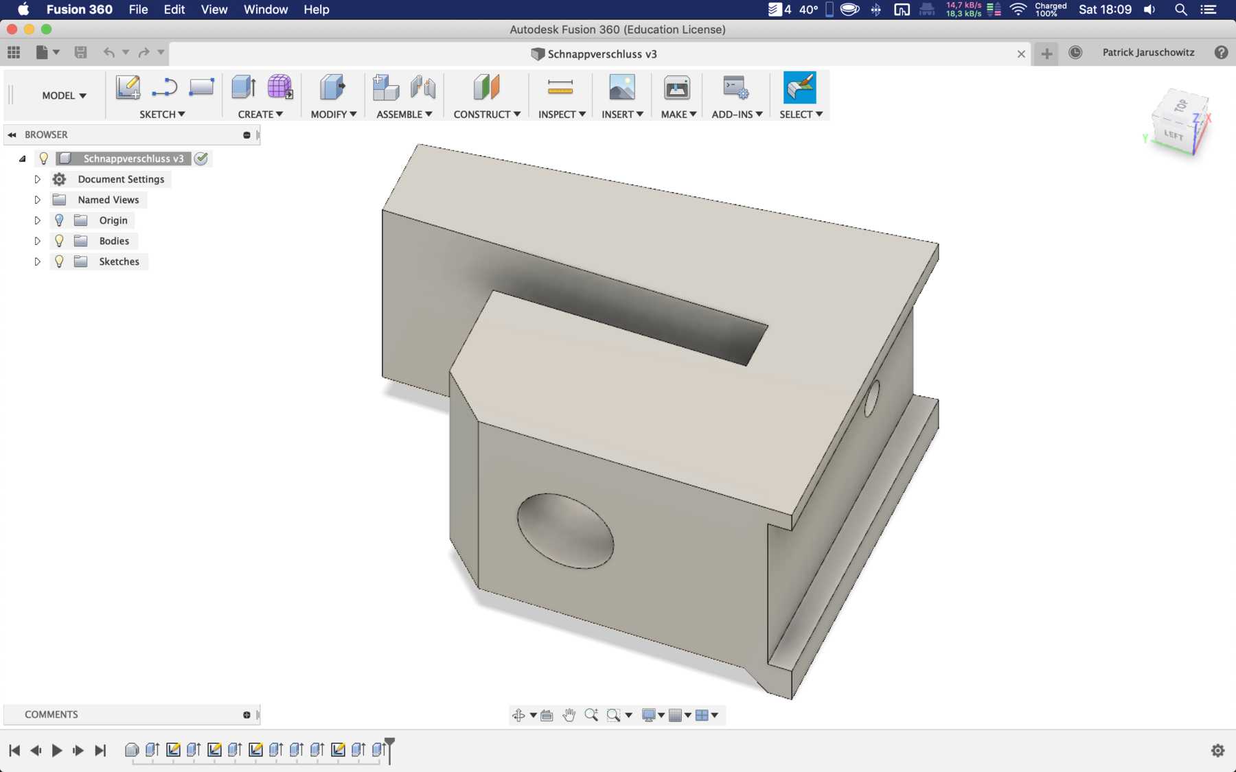
MICRO SWITCH
The Micro switch still had to be attached to a profile. The following design was sufficient:
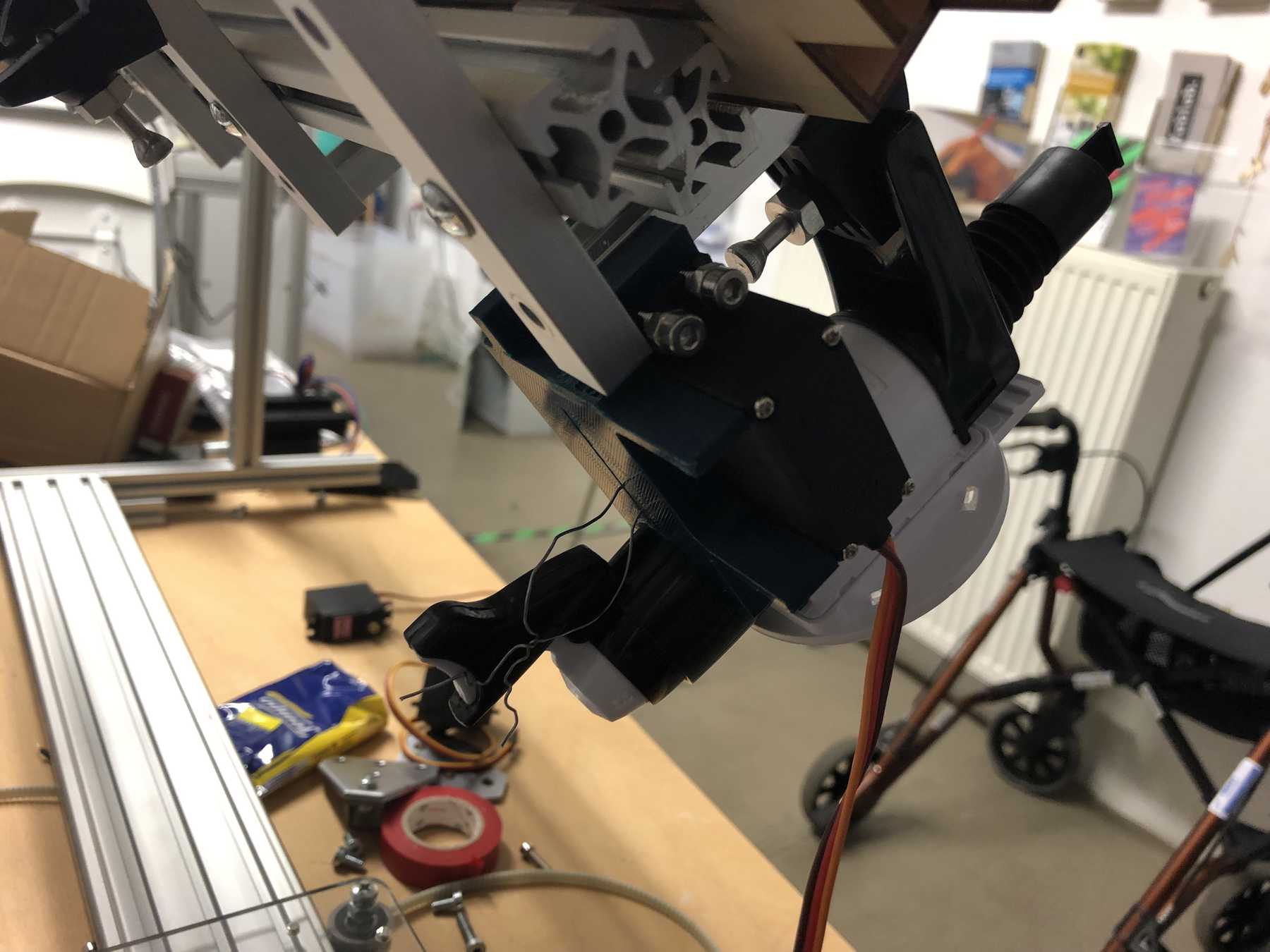
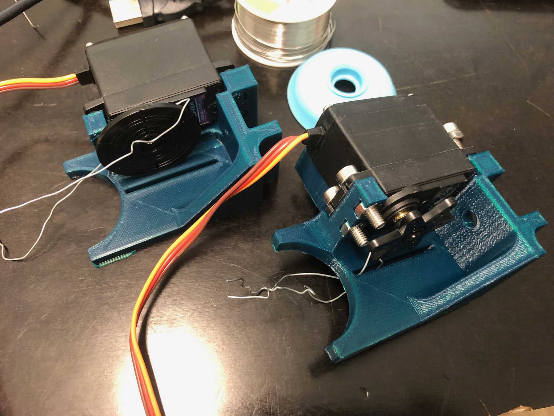
DESIGNING THE BOTTLE HOLDER
The next step was to design the bottle holder. The whole thing took countless iterations until everything actually worked. The difficulty was that sometimes only small details didn’t make it possible. Despite planning, you always overlook something in the fast track. Also the integration of the servo, the proper gear and a possible mechanism over a wire are shown. We will see whether the wire is a long-term solution.
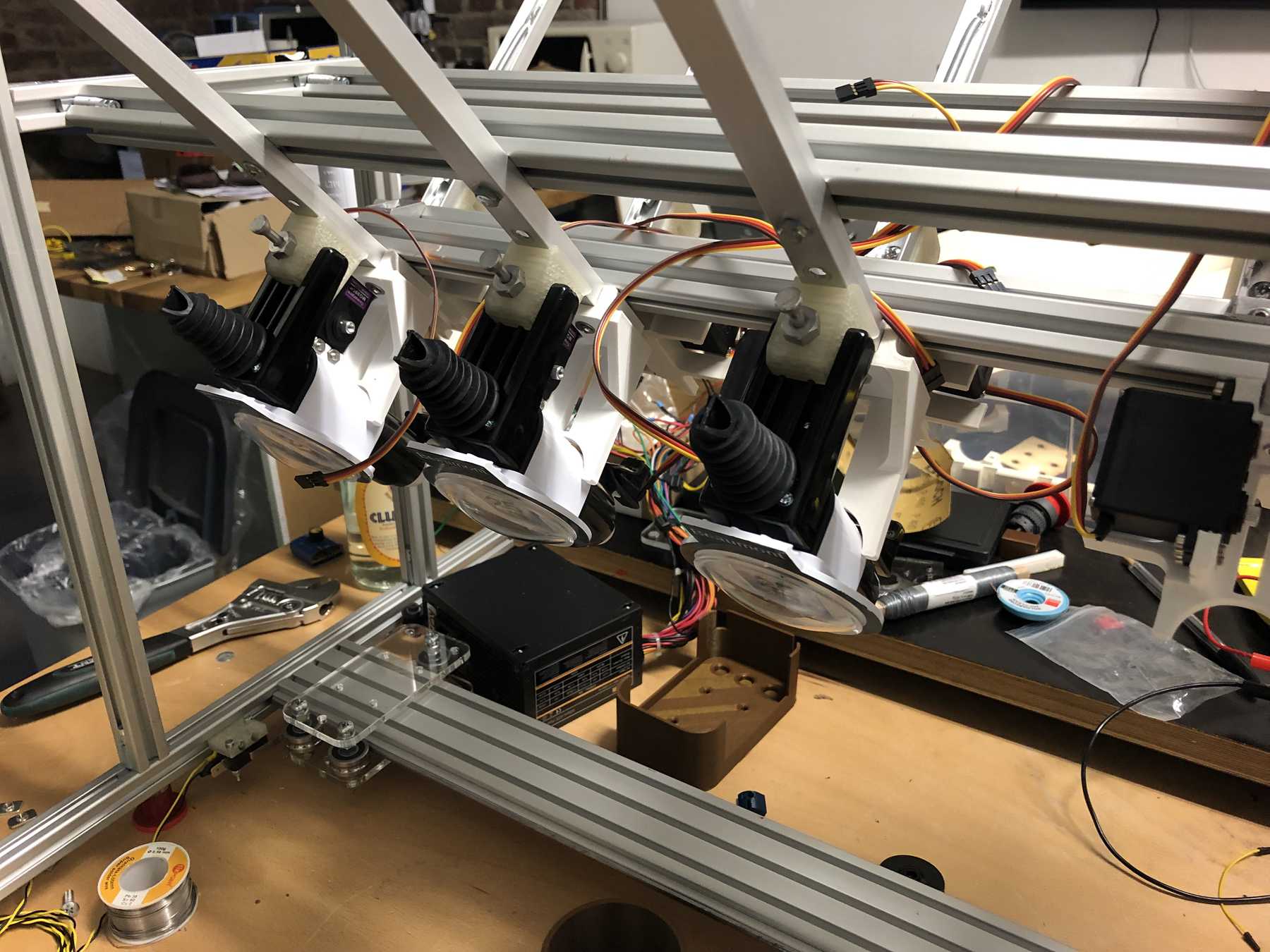
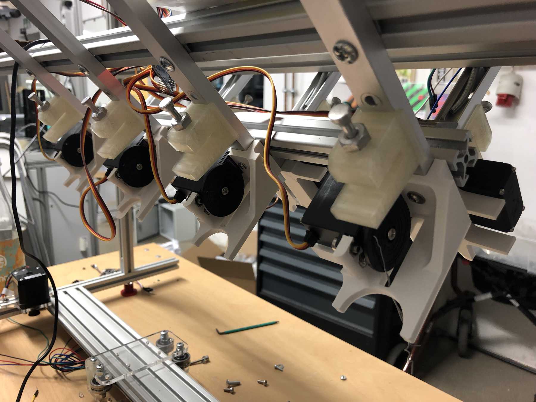
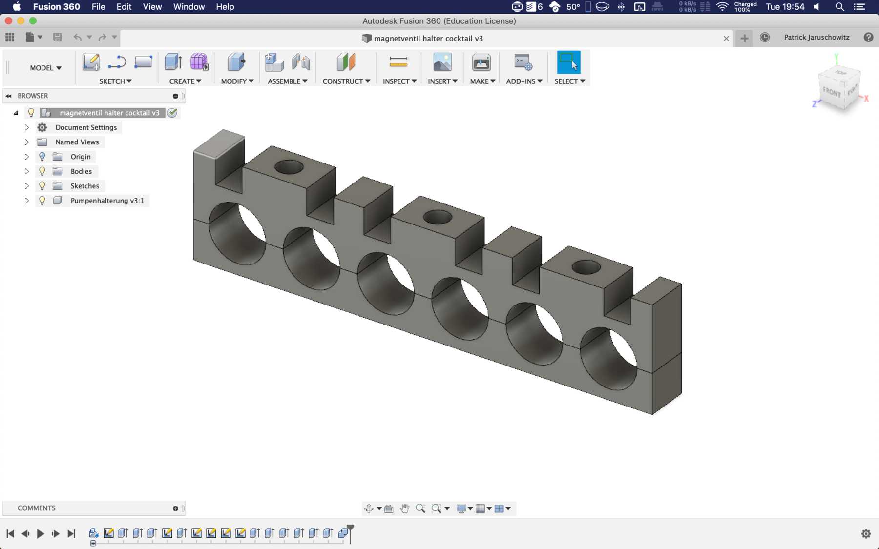
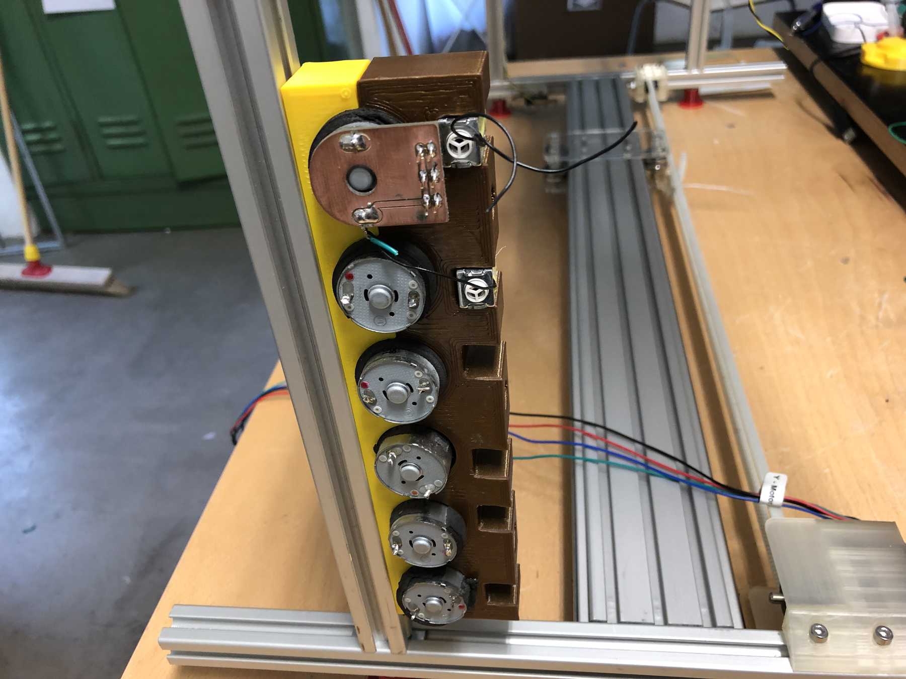
MOUNTING THE PUMPS
We have removed pumps from old blood pressure measuring devices from an earlier event. Finally we can use them in a cocktail machine. Therefore we disassembled everything and built the following mount.
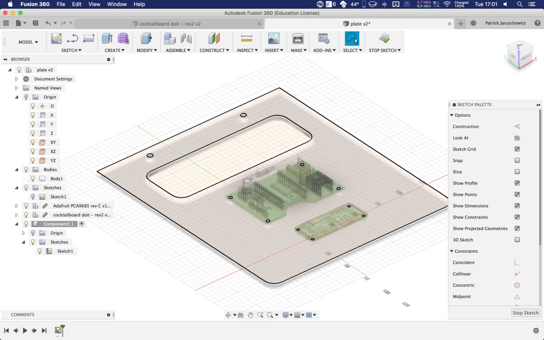
COMPARTMENT FOR ELECTRONICS
The electronics should be placed in a simple box in the prototype. We designed something where you can just put the electronics on top. Here are some pictures:
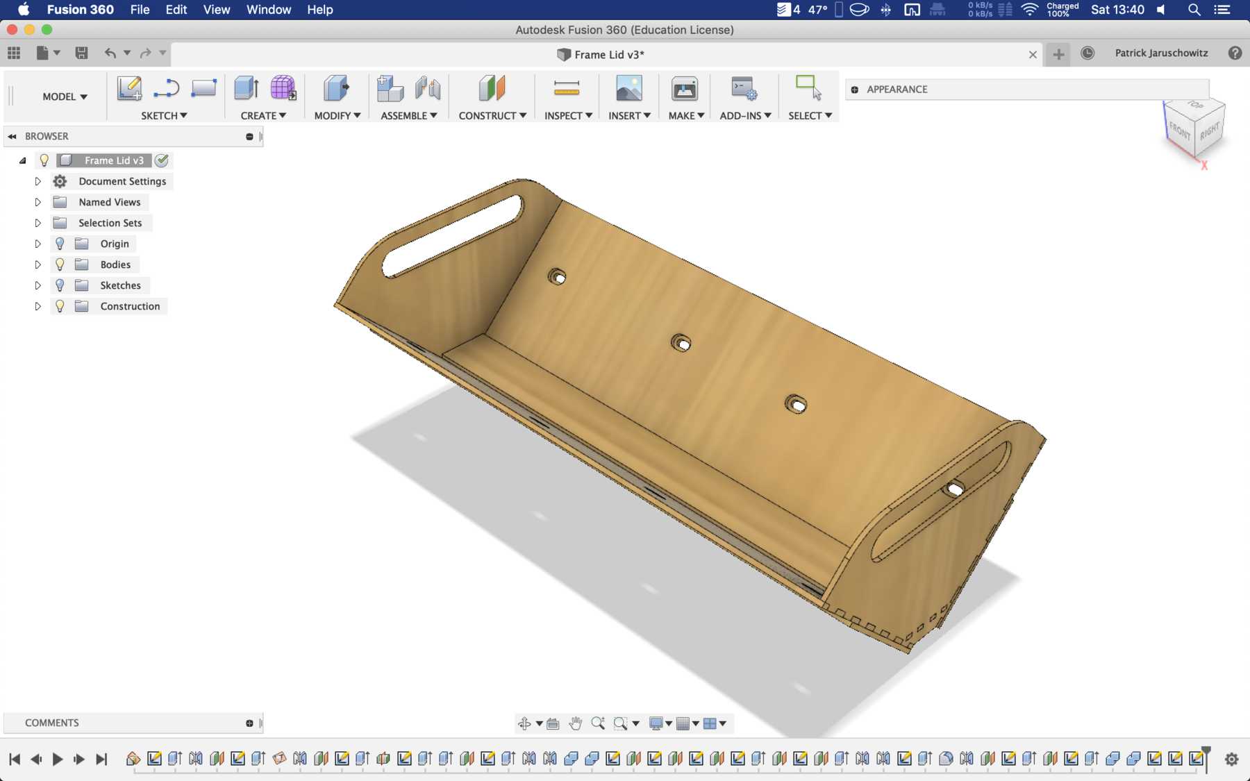
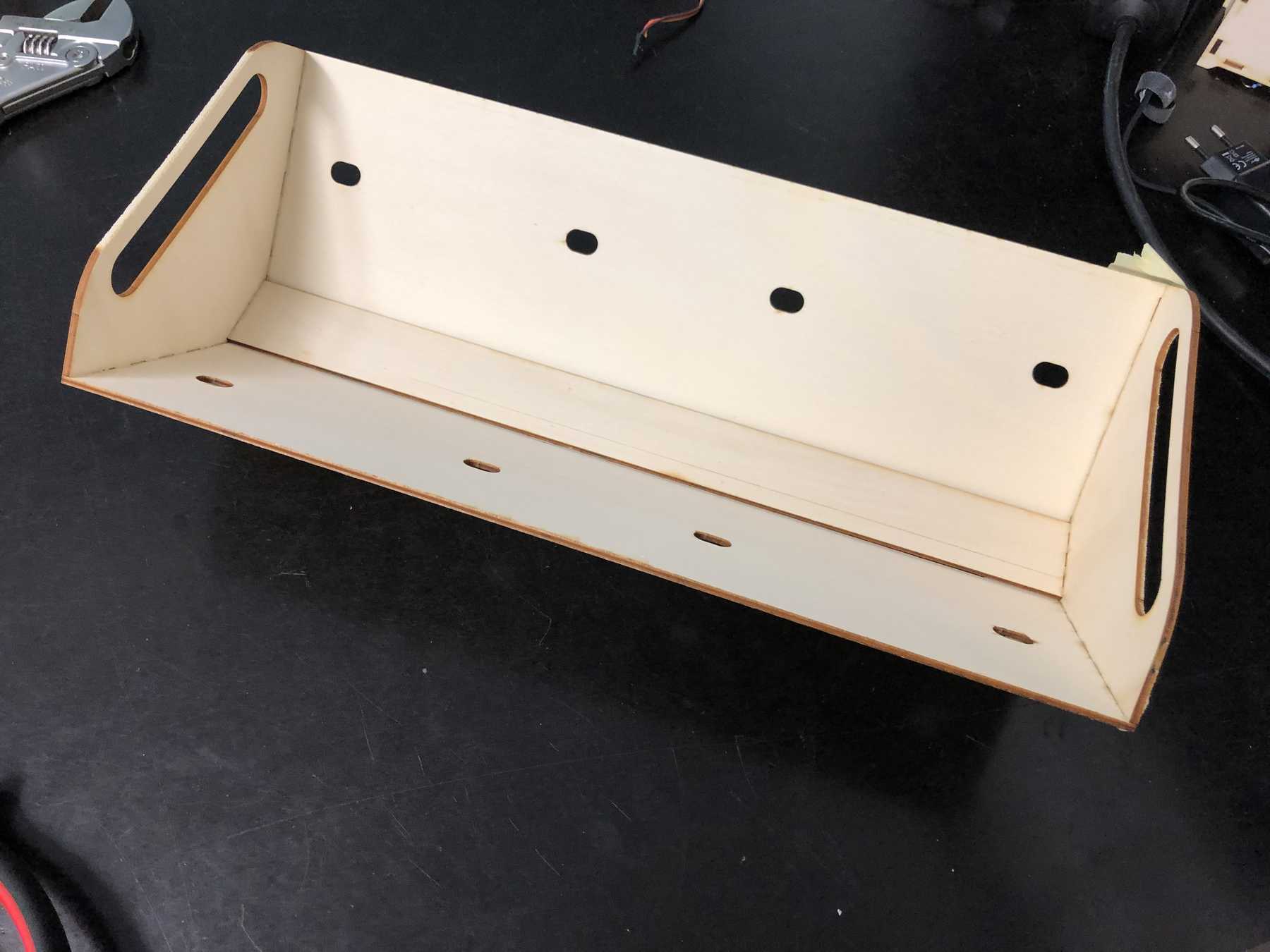
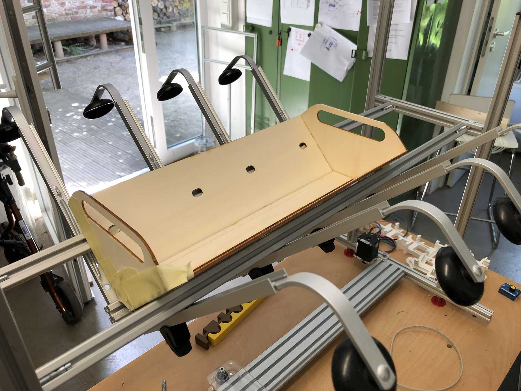
Later we changed it into the following design:
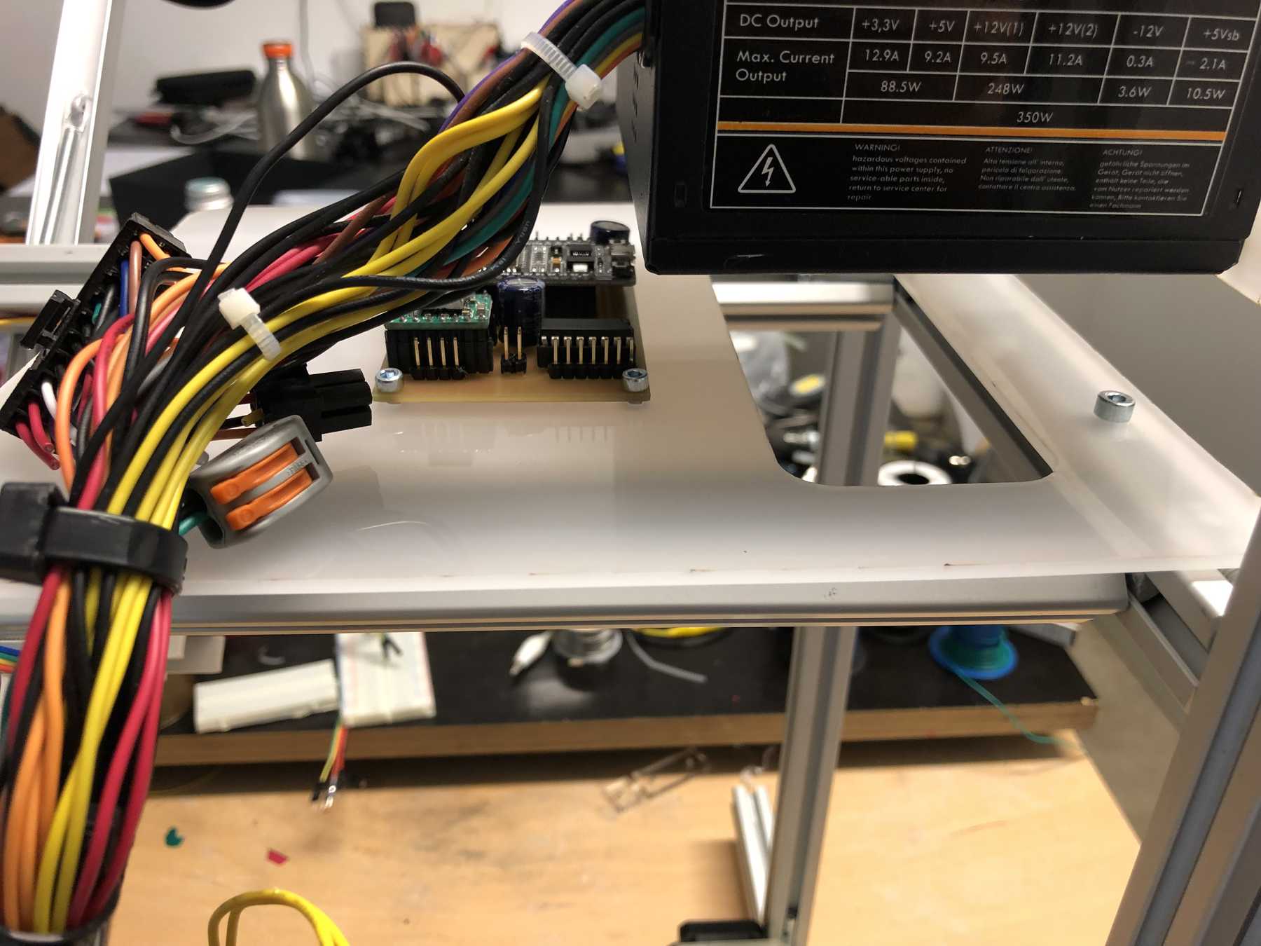
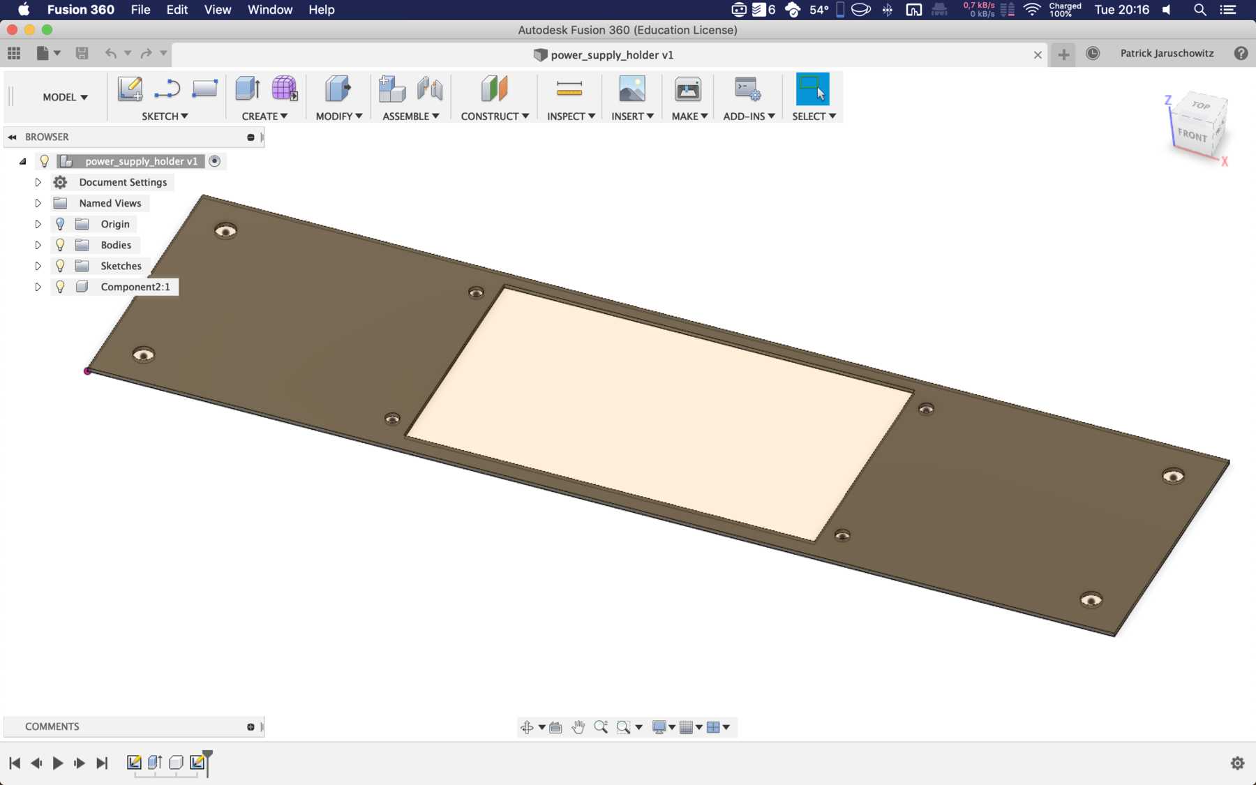
MOUNTING FOR THE POWER SUPPLY
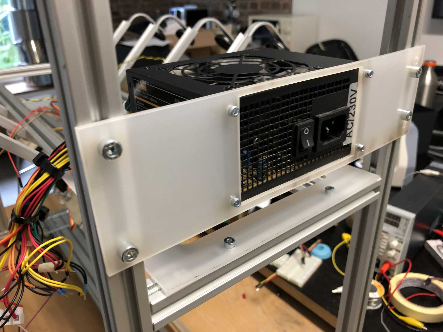
Conclusion: Little time, a lot of work, but a very nice result. After the Fab Academy, some small things can and will be optimized.
Finally, a video documenting the construction: