Welcome to Berytech Fab Lab
So the objective of those two weeks was to discover and experience how to design and build a mechanical machine that can accomplish a certain goal or objective by a system of mechanical components, electric circuit, and a controlling code.
This week had a wide range of ideas that could be done. Many ideas could be found in previous Fab Academy years and on other online resources. We can make a CNC Machine, a plotter, laser cutter, 3d printer and many other more, all of which have the same main concept, a sytem of stepper and servo motors, that control a specific head, to produce a specific final product.
Group Assinment
We had a Group Assignment for two week.
A Machine is an apparatus using mechanical power and having several parts, each with a definite function and together performing a particular task.
Machines Used
The main machine used in this week's assignment is the Desktop CNC Machine.
In this assignment we had to work as a group, and based on the resources we have in the lab; the maximum Rod length available is 40cm so our two axis machine will be limited to 40 x 40 cm .
For that we decided to create a machine that has the Y axis on the Rod and the X axis on wheels:
The Y axis is limited to 40cm (maximum Rod Lenght) and the X axis is unlimited and it will be on wheels.
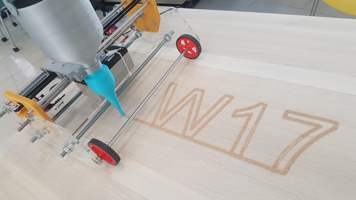
Our machine will be a sand plotter ; it can be placed on the floor and make drawings with sand of 40cm width and unlimited lenght
The project is divide into 4 parts and distributed on the 4 group members:
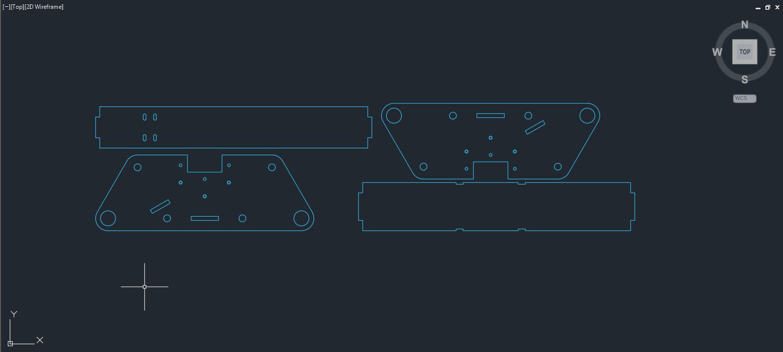
For the main body I started sketching on Autocad to visualize the overall dimensions with all the parts
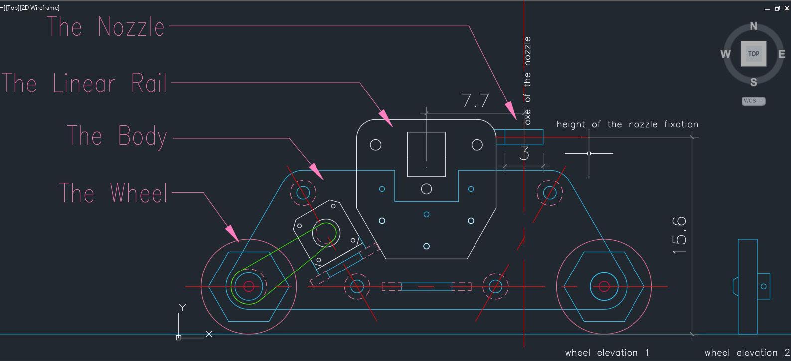
And below is the main body details
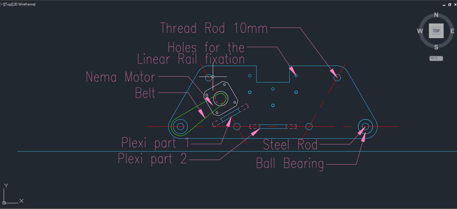
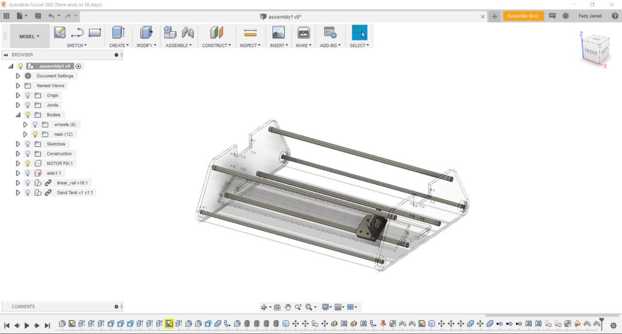
The Idea is to have 2 main plexi part (6mm thicknes) linked together with four 10mm Threaded Rod. Four ball bearing will be inserted in the plexi part to hold two 8mm steel Rod which will hold the wheels.
Two other plexi parts will are placed perpendicularly between the main plexi part to give more rigidity to the body ; Plexi part 1 will hold the Nema motor and the Plexi part2 will be holding the Battery and the Electronic Board.
Three holes are made in the main plexi in order to hold the Linear Rail.
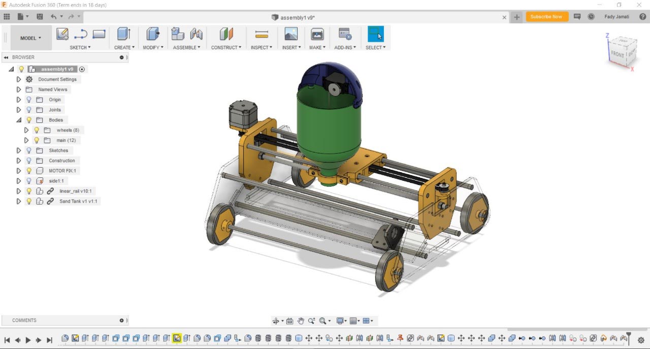
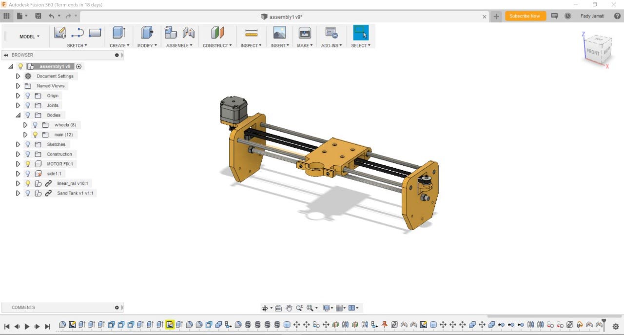
Now I will insert the dxf sketch on fusion to 3D model it and visualize it with the other parts.
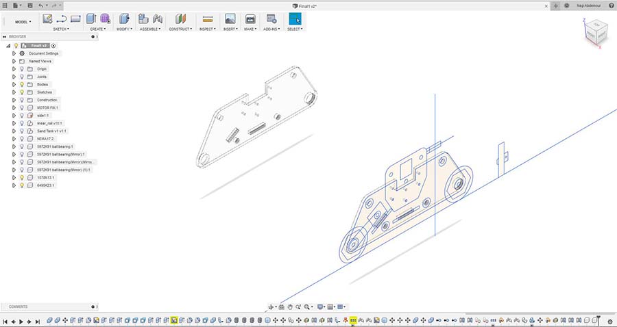
After drawing the 2 main plexi pats , now I will draw the Plexi part 1 and Plexi part 2
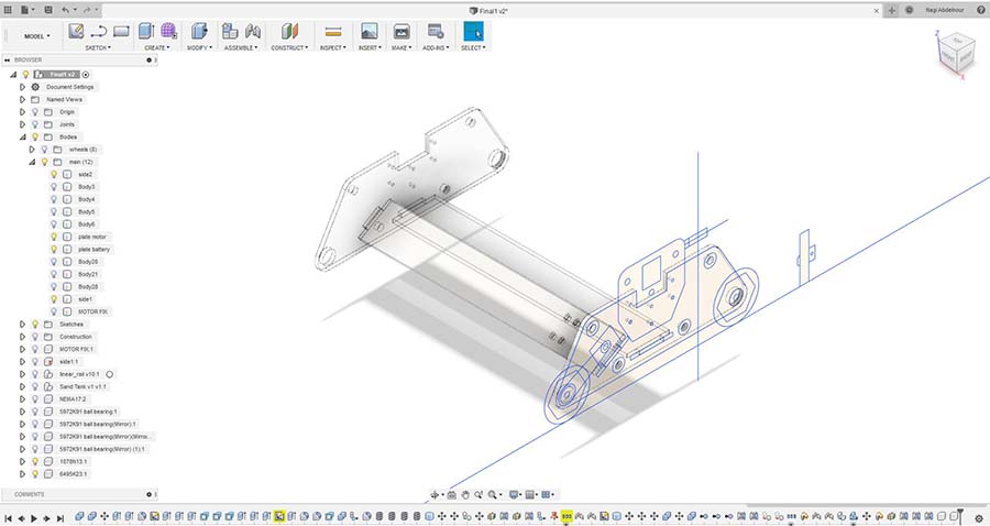
Now I will add the 10mm Threaded Rod linking the main parts together.
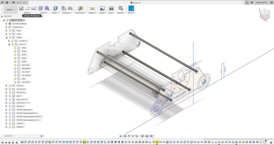
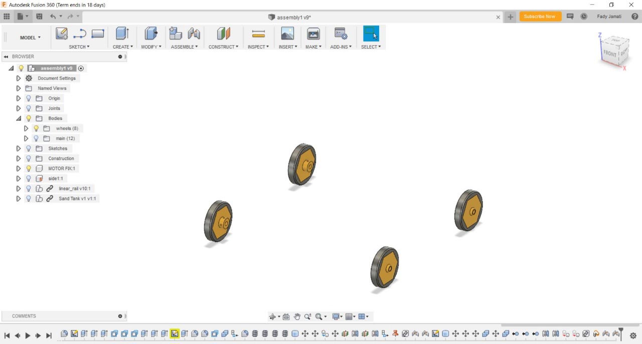
Than I will add the two 8mm Steel Rod and the four ball bearing holding the wheels.
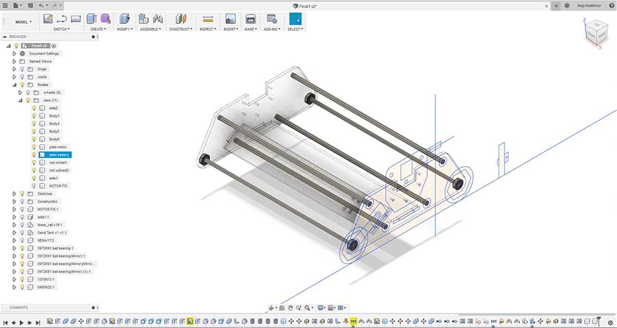
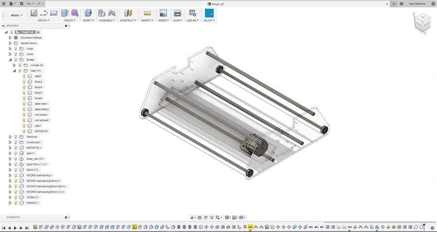
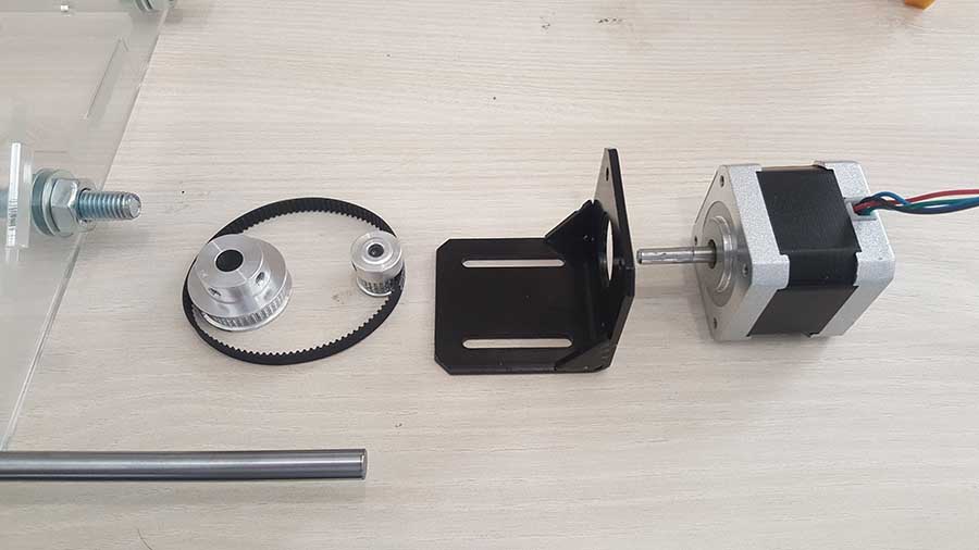
And finally I will add the Nema motor and it's support.
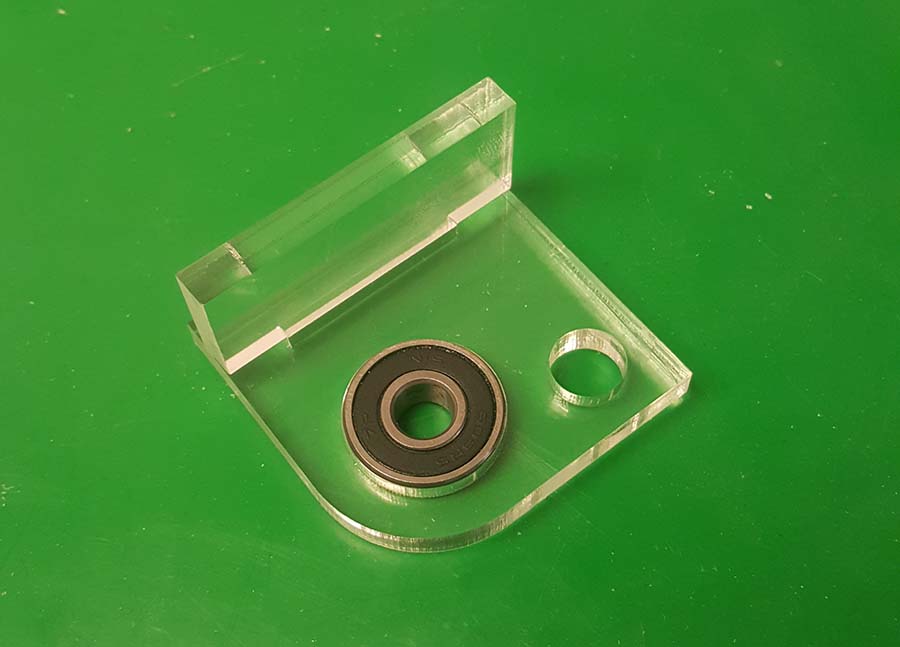
The ball bearing should be tightly inserted in the plexi part: for that some testing should be made and calculate the kurf.
The ball bearing diameter is 22mm and the best fitting hole turned to be 21.8mm and the kurf is 0.1mm
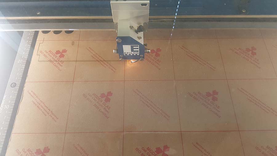
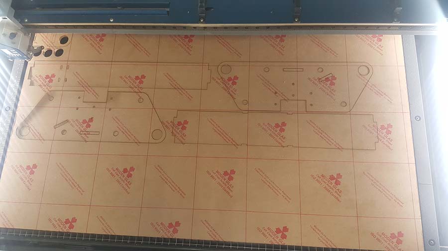
Based on that I will adjust the design, extract the dxf profiles and prepare them for plexi laser cutting.
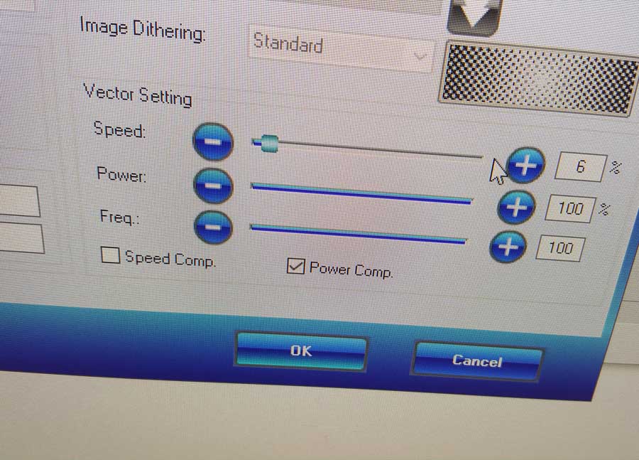
Laser cutting the parts.
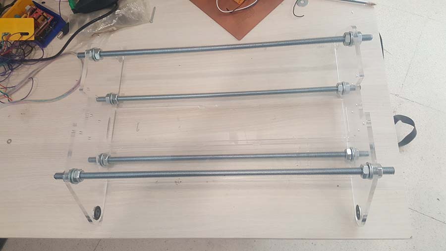
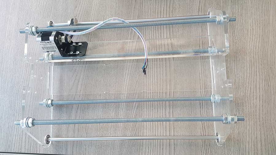
I will start by assembling the plexi parts and the threaded rods.
Than I will assemble the motor with it's fixation , the pulleys , the belt and the rod that will hod the wheels.
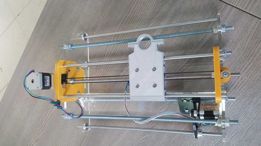
And finally we will fix the Main body and the Linear rail parts together
For more details Check Nagi's page for more details on the process.
Check Nour's page for more details on the process.
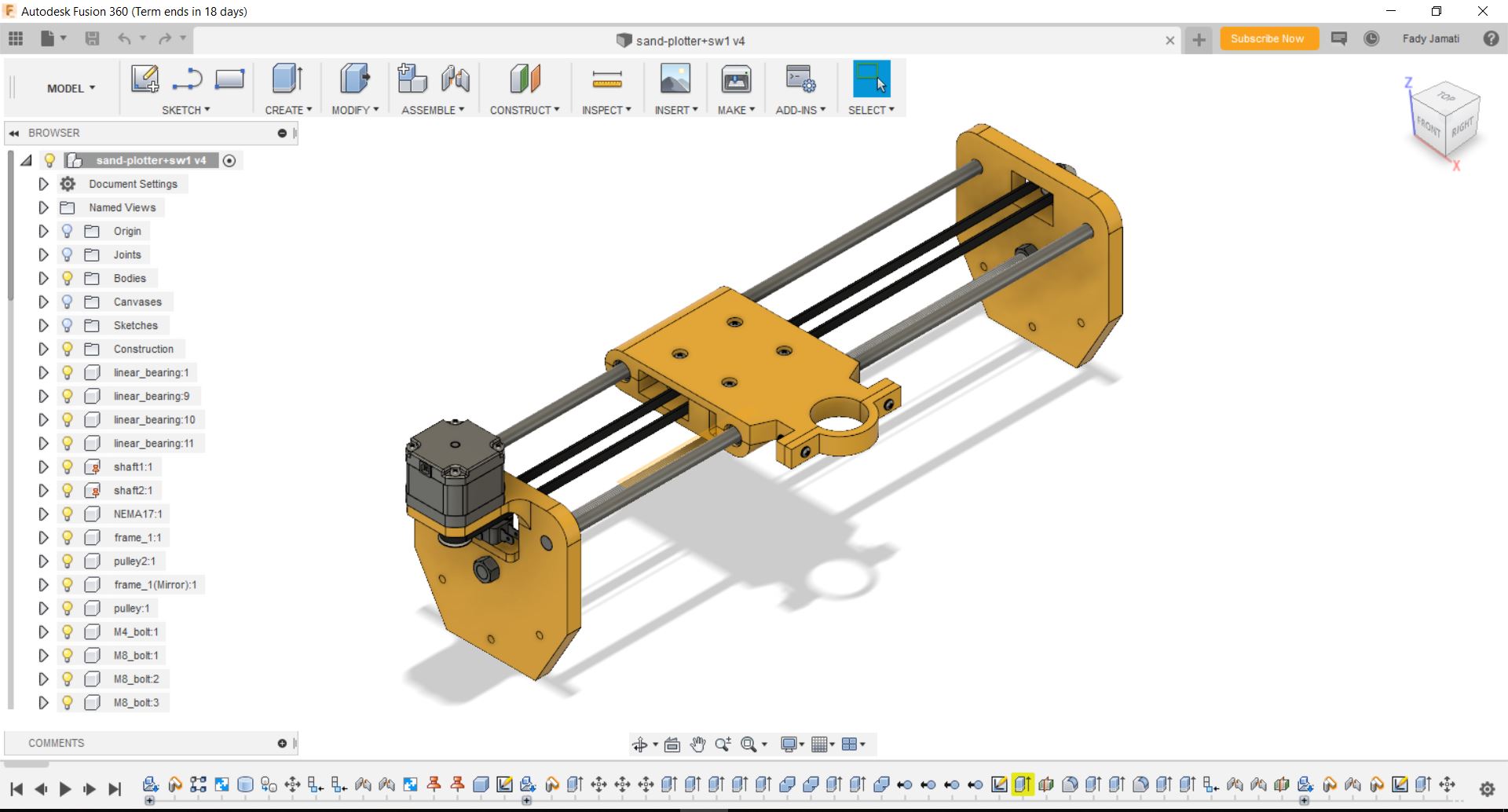
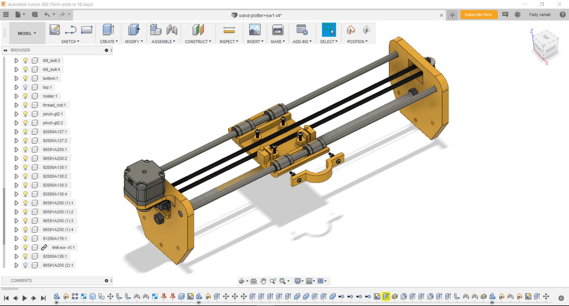
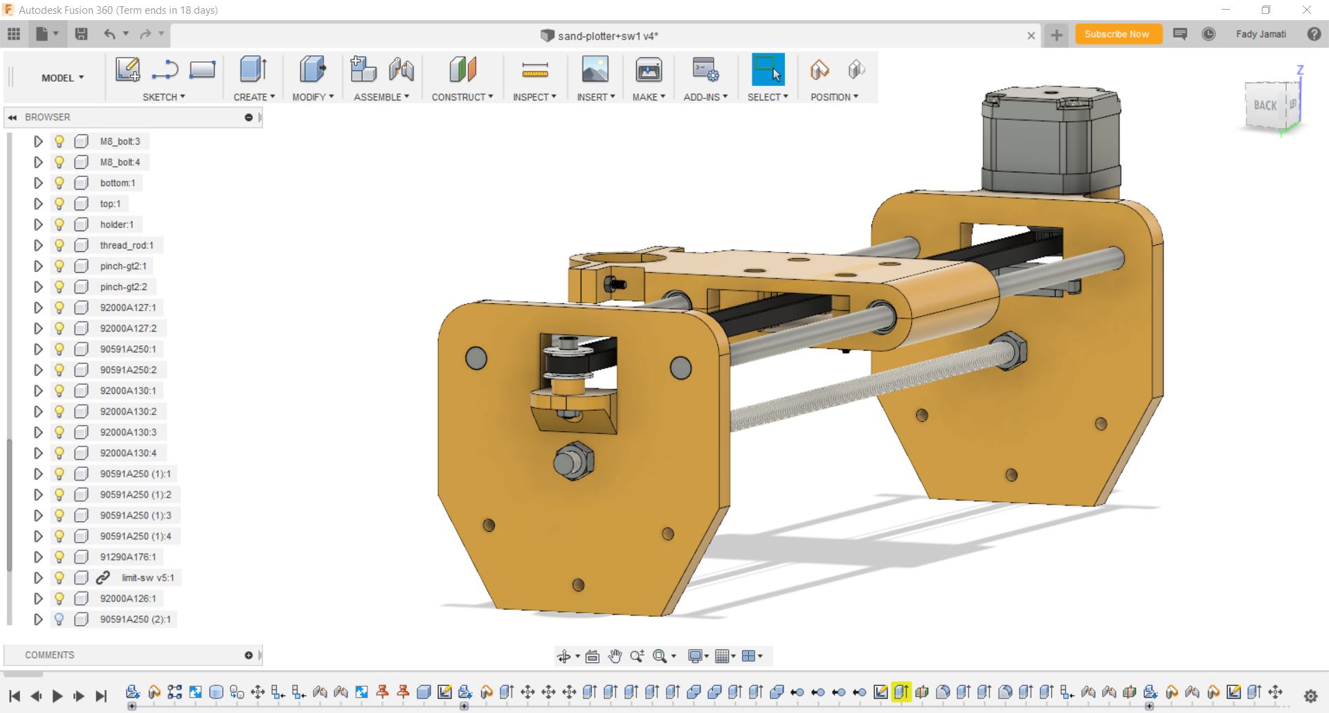
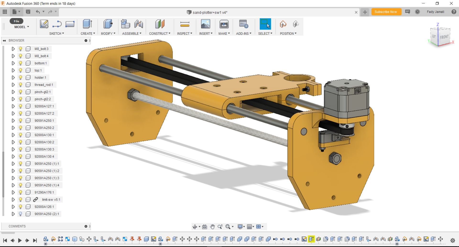
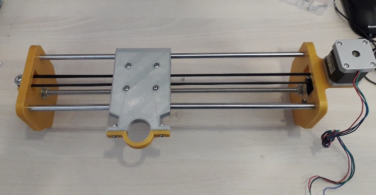
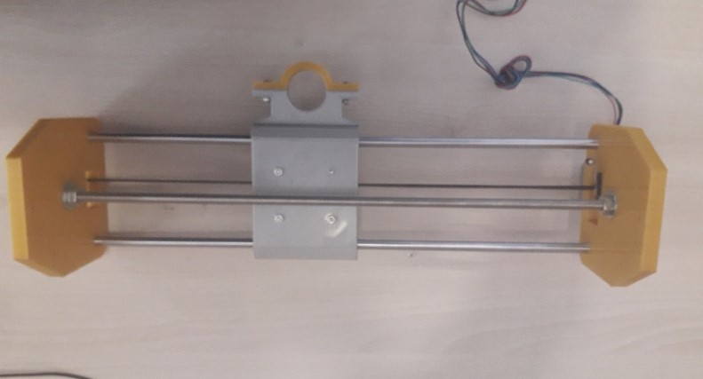
The design includes two linear rail which are 40cm stainless steel rods, four linear bearings, a stepper motor, a limit switch, and a gt2 6mm driving belt. The rails are held by two side frames and a threaded rod. The linear bearings are fitted to a moving plate which consists of three parts, a top part wich include grooves for fixing the driving belt, and a top part with is attached by screws and bolts to a holder meant to fix the container. The top and bottom part are also attached by screws and bolts.
Note: The design shows the driving belt as closed, but in the assembly the driving belt will be cut and fixed in the grooves in the bottom plate.
View A
View B
View C
View D
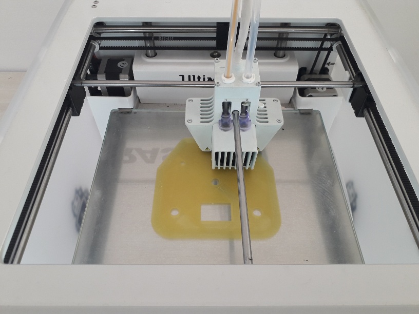
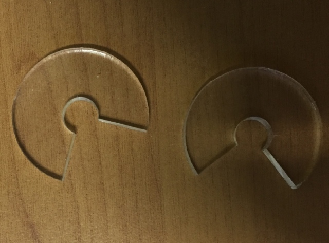
The next step was to 3D print the side frames and the moving plate parts. I used the Ultimaker 3D printer
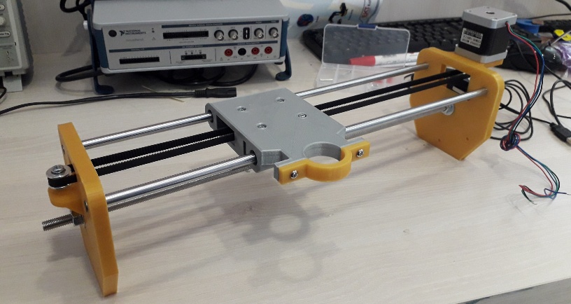
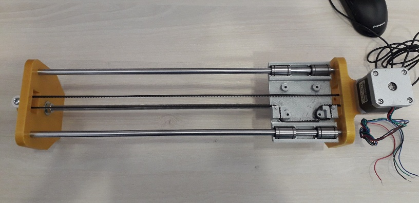
The next step was to assemble the module. The linear rail module is meant to be assembled with the main body, but first I assembled the module separately. The parts fit well which is the most important. The driving belt fist tightly in the grooves. I little hiccup was that on the grooves was not mirrored with the other, so the driving belt is fixed in different ways on the two grooves (picture C).
View A
View B
View C
View D
The final assembly of the CAD design looks like this
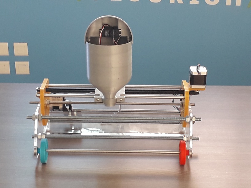
he assembly of the real parts is nearly finished. Still missing a couple of wheels as well as the tires.
For more details Check Fadi's page for more details on the process.

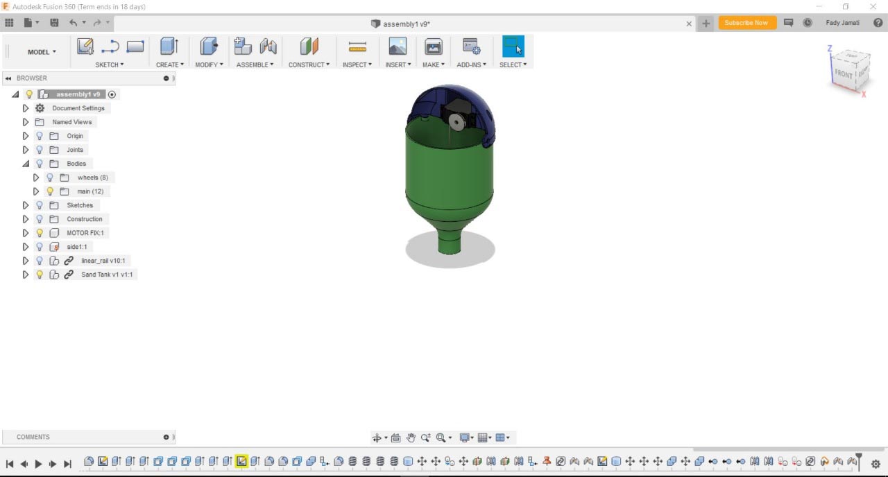
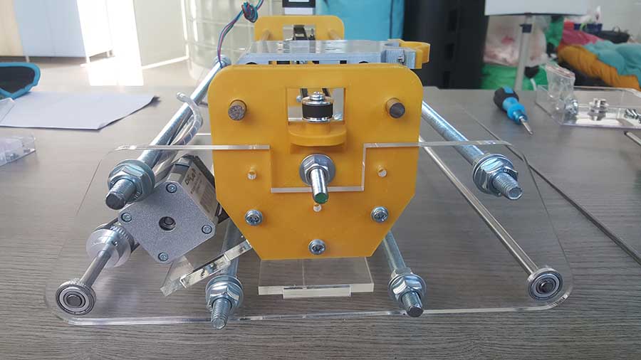
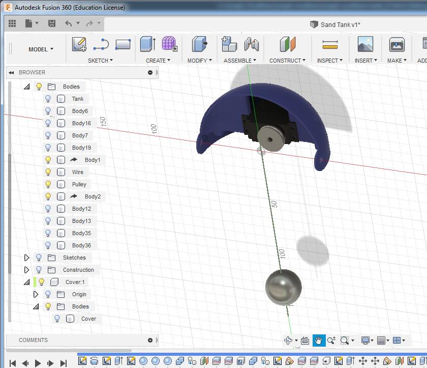
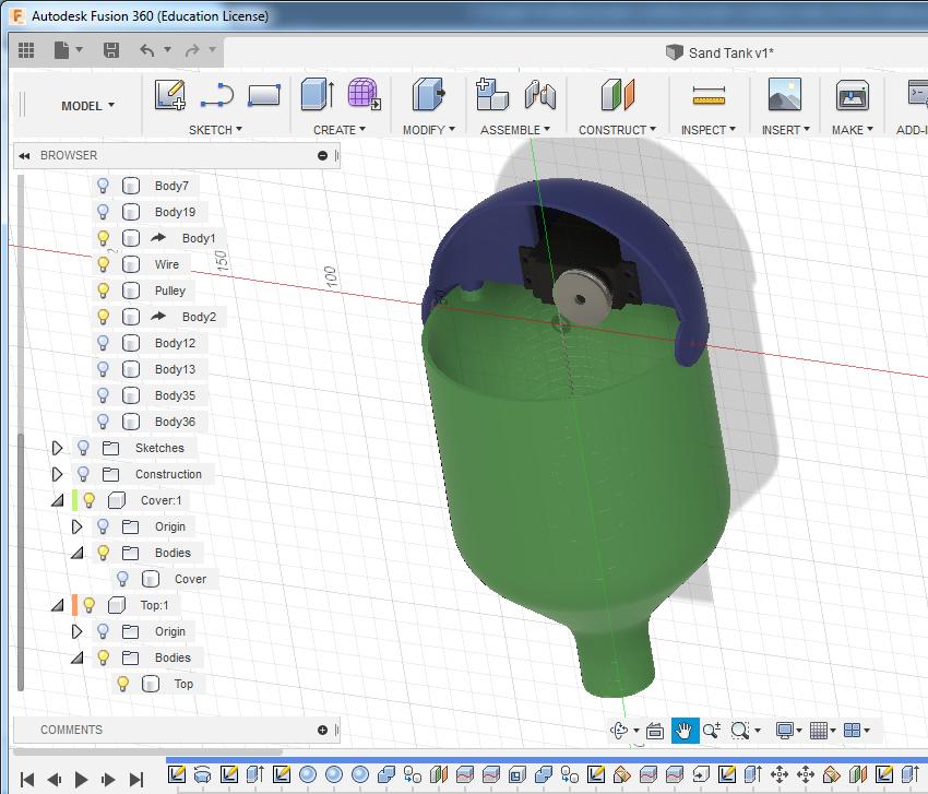
The team members suggested an improvement of the basic idea by changing the valve closing mechanism. The concept is to use a sphere to close the container outlet and commend it by a servo motor fixed in the top of the container in an enclosed design.
The design of the 32 mm sphere:
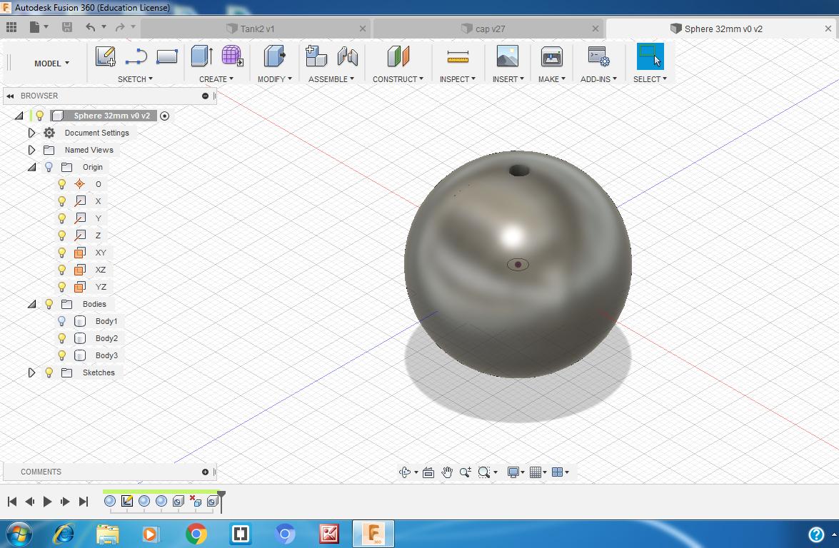
After 3D printing a first prototype of the sphere we discovered that it needs to me more heavy so we decided to 3D print another sphere by softly minimizing its diameter and filling it with more material by using the (fill) option.
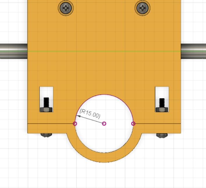
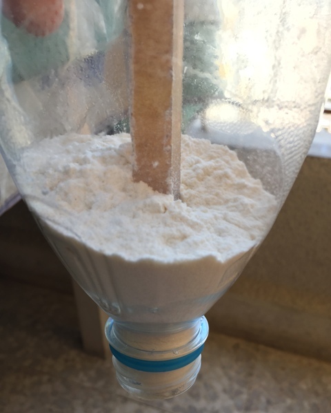
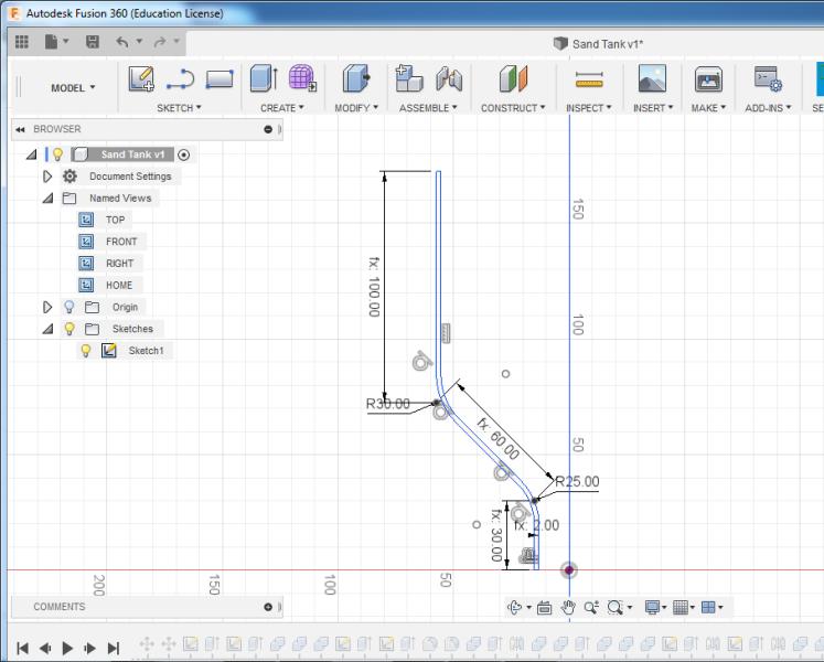
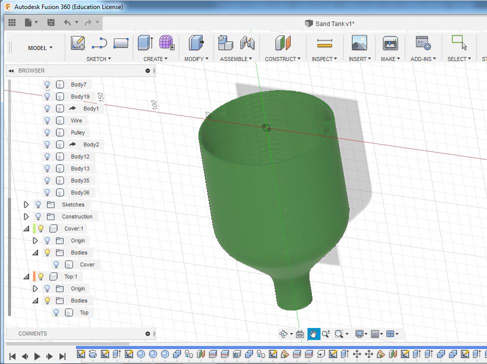
I draw the container according to the above holder inner diameter (30mm), and 3D printed it.
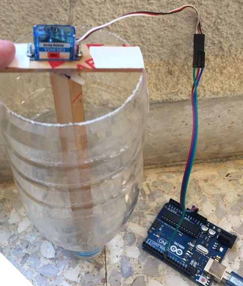
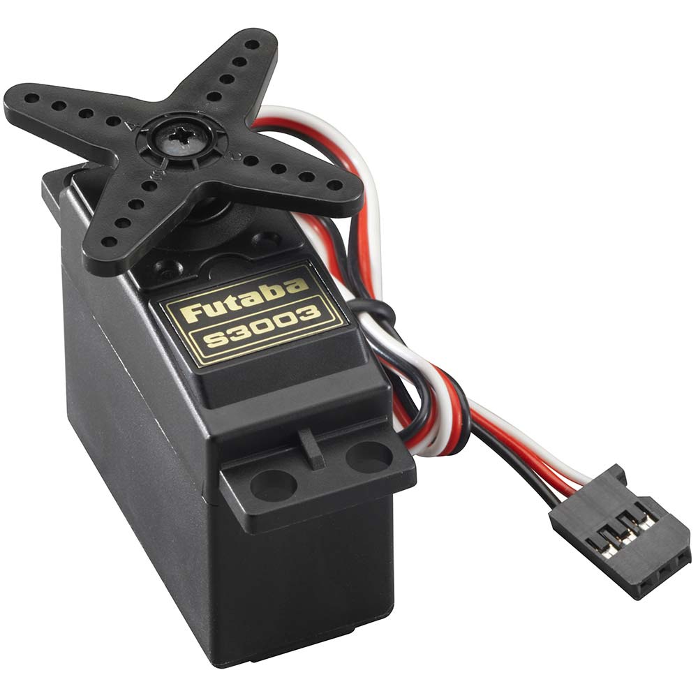
I used Futaba S3003 servo motor:
The cord is positioned in the center of the tank to be able to move up and down the sphere and open/close the lower outlet. According to the wheel diameter the servo is fixed off-center.
Click Here to download the original design files
Our sand plotter machine , has 2 axis with 2 stepper motors , the x axis is on wheels and it has no limitation in lenght as for the Y axis it is on rods and it is limited to the rod lenght( 40cm )
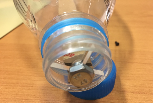
The sand tank is controlled by a servo motor. The srevo motor is connected to a ball with a string inside the sand tank ; when the ball goes down it opens the sand tank nozzle and releases the sand and when it goes up it closes the nozzle and the sand stop going down.
We used a grbl-Servo library to control the arduino and the motors.
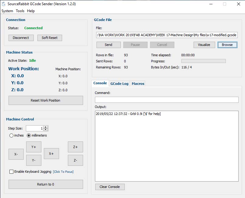
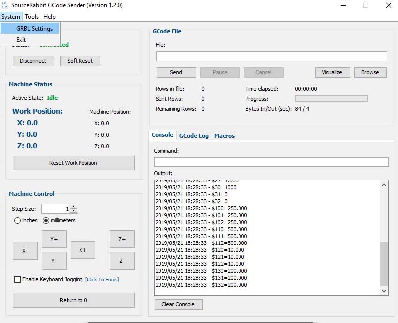
The arduino is than connected to a gcode sender. In our case we used Source Rabbit gcode sender. We had to modify some settings to match our machine gears and wheels dimensions.
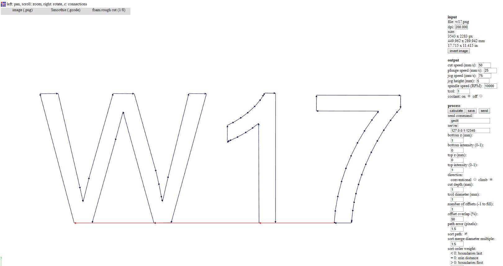
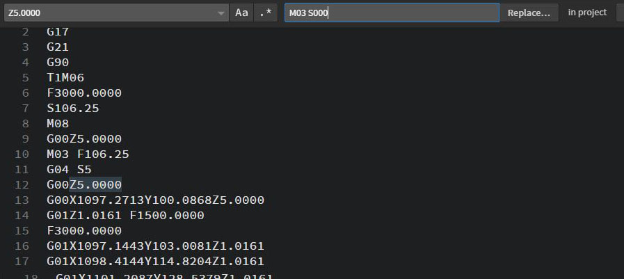
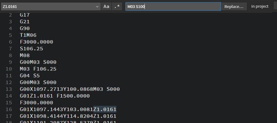
The gcode was generated in fabmodules and we had to modify it in brackets in order to adjust the Z values to work with the grbl-Servo we used.
And the different steps done are detailed below:
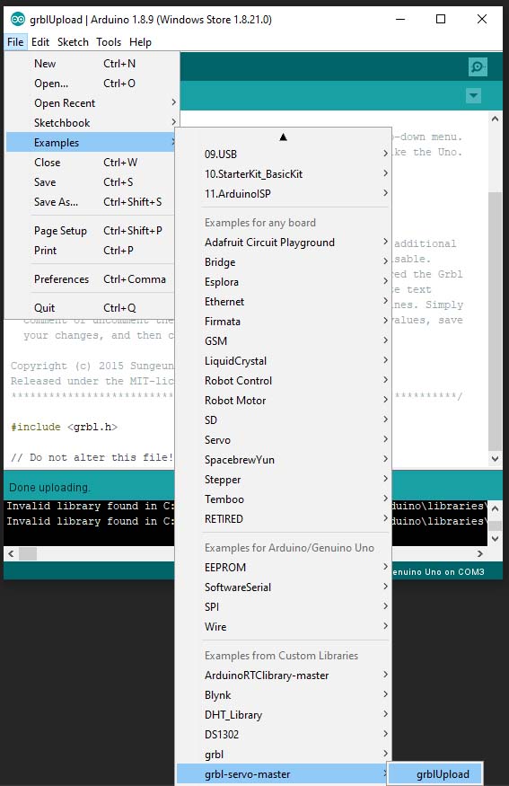
First we need to download the grbl library and include it in the Arduino IDE libraries folder. We will use the grbl-servo lirary since we have a servo motor in our machine and to be able to control it through the gcode.

Than we have to clear the eprom
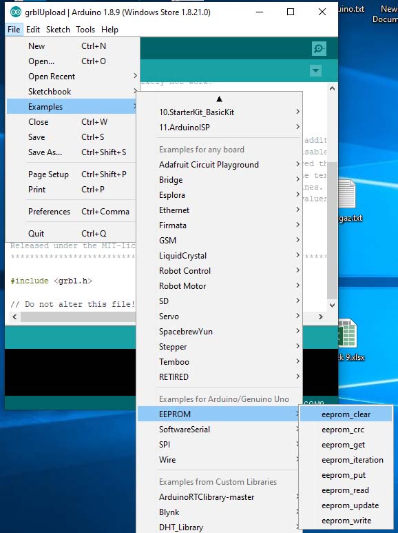
And upload the grbl from the examples folder
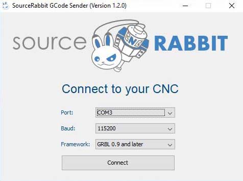
We will download the SourceRabbit gcode sender and install it.
And than we will connect to the port COM3 and Baud 115200 to match the connected Arduino port.
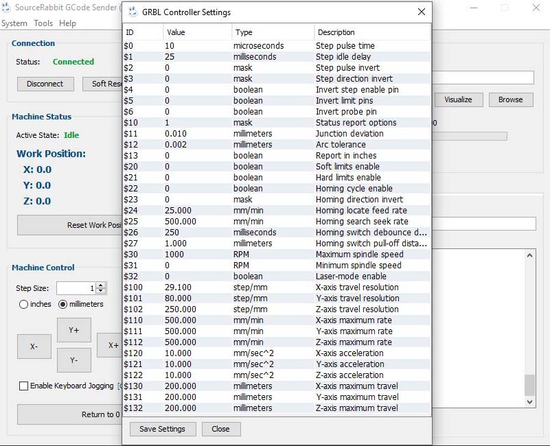
Now we need to configurate the grbl settings to match our machine gears and dimensions
X-axis resolution = 29.1
y-axis resolution = 80
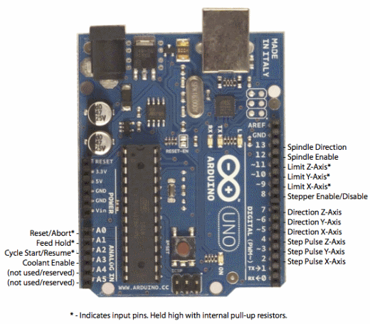
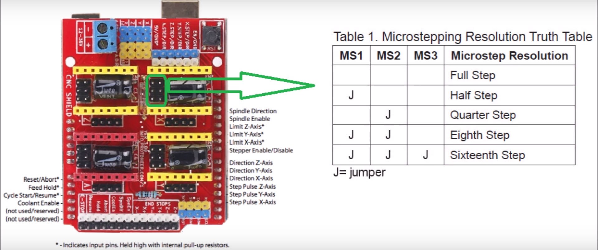
We will be using an Arduino with CNC Shield
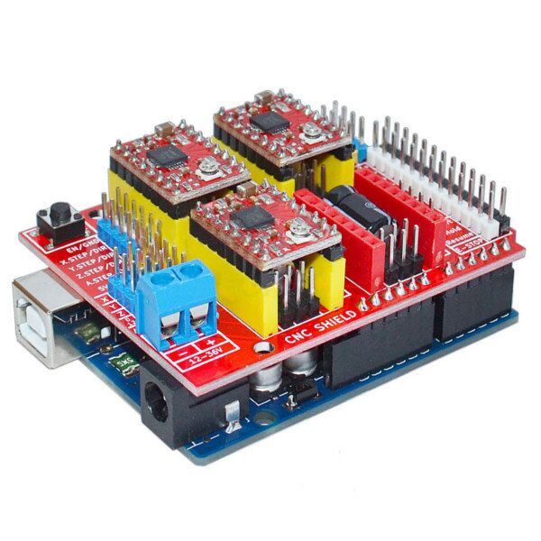
On the CNC shield we will plug a Stepper motor driver A4988 and place jumpers for micro stepping
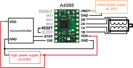
Now we will connect the 2 stepper motors on the X & Y axis and the servo motor on pin 11 (SIGNAL on the Z+ END STOPS)
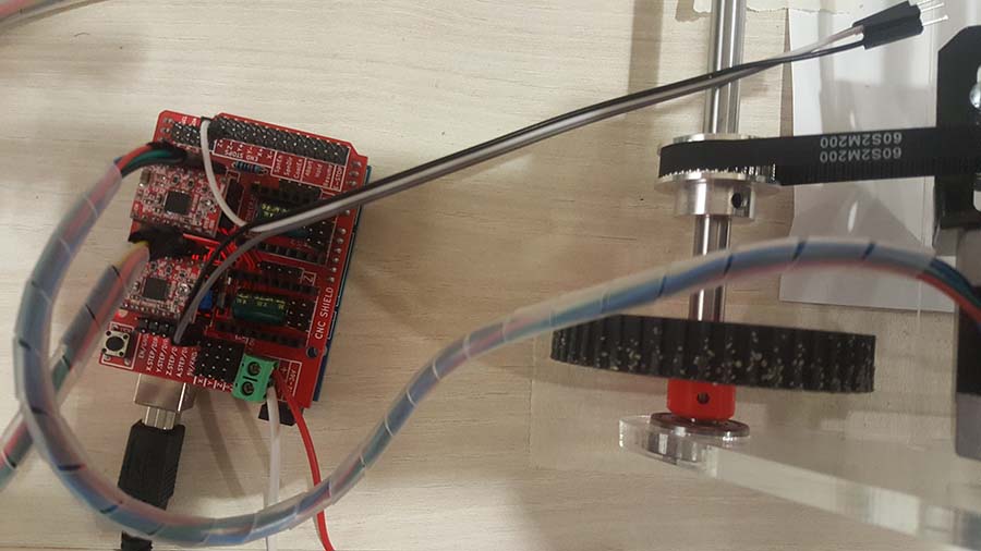
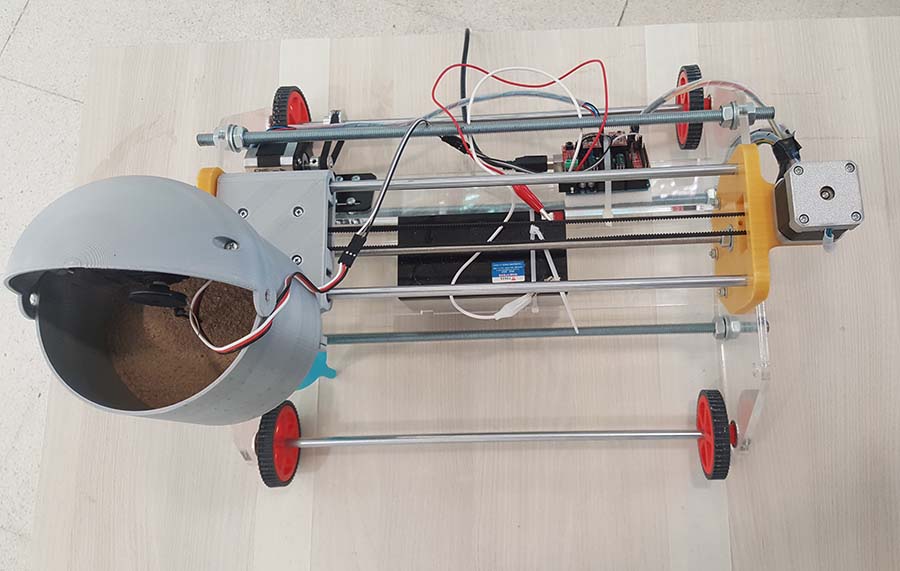
And this is the final machine assembled
We will use the fabmodules to generate the gcode with the below settings
Now we will modify the gcode on brackets in order to control the servo and change the below values
Click Here to download the original gcode
Click Here to download the modified gcode
We will connect to the board through Source Rabbit Gcode Sender , load the modified gcode and press send