Welcome to Berytech Fab Lab
So the objective of this week is to get introduced to using input devices. Input devices could be anything that send a signal or data to a microcontroller, which could be either digital or analog.
There are many input devices in the market that could be used to gather data and connect the electronics system to the outside world. Those input devices could be a switch, distance sensors (Ultrasonic or Infrared), magnetic sensors, temperature sensor, light sensor, accelerometers and gyro sensors, sound sensors (microphones), vibration sensors, cameras and much more. Technically everything you see in all the equipment and machines you use in your daily life, like the iphone.
In this section, we will learn on how to use and connect a sensor to a microcontroller, and how to use it to collect data from its surrounding.
Group Assinment
The group assginment was to Measure the analog levels and digital signals in an input device.
An input device is any hardware device that sends data to a computer, allowing you to interact with and control it. The picture shows a Logitech trackball mouse, which is an example of an input device.
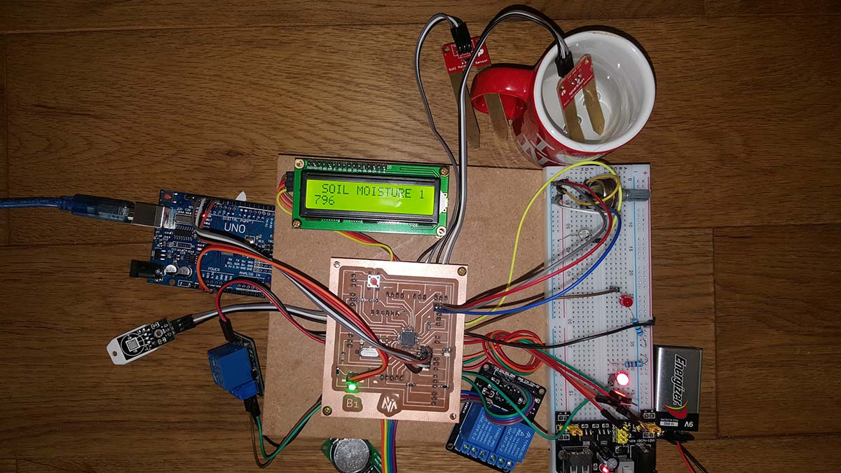
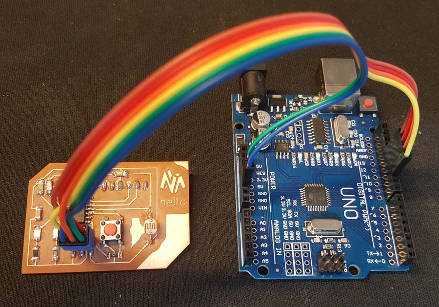
In this group assignment we are going to read an analog input on the Tektronix TBS1052B Digital Oscilloscope. For that we used my hello board from Week7 Electronic Design on which I have an LDR.
Below is the code used; When I push the Button; If there is light than the Green led should turn on, if not the Red led should turn on
                                // constants won't change. Used here to set a pin number:
                                const int buttonPin = 3;//the number of the pushbutton pin
                                const int ldrPin = A2;//the number of LDR pin
                                const int ledPingreen = 8;// the number of the greenLED pin
                                const int ledPinred = 7;// the number of the redLED pin

                                // Variables will change:
                                int ledState = LOW; // ledState used to set the LED

                                int buttonState = 0;
                                int sensorValue = 0; // variable to store the value coming from the sensor

                                int value = 0;

                                void setup()
                                {
                                // put your setup code here, to run once:
                                // set the digital pin as output:
                                pinMode(ledPingreen, OUTPUT);
                                pinMode(ledPinred, OUTPUT);

                                // set the digital pin as input:
                                pinMode(buttonPin, INPUT);
                                pinMode(ldrPin, INPUT);

                                }

                                void loop()
                                {
                                // read the state of the pushbutton value:
                                buttonState = digitalRead(buttonPin);

                                // check if the pushbutton is pressed. If it is, the buttonState is HIGH:
                                if (buttonState == HIGH)
                                {
                                // read the value from the sensor:
                                sensorValue = analogRead(ldrPin);
                                value = map(sensorValue,0,1023,0,100);
                                if ( value>50)
                                {
                                // put your main code here, to run repeatedly:
                                digitalWrite(ledPingreen, HIGH); // turn the LED on (HIGH is the voltage level)
                                digitalWrite(ledPinred, LOW); // turn the LED on (HIGH is the voltage level)
                                delay(1000);
                                }
                                else
                                {
                                // put your main code here, to run repeatedly:
                                digitalWrite(ledPingreen, LOW); // turn the LED on (HIGH is the voltage level)
                                digitalWrite(ledPinred, HIGH); // turn the LED on (HIGH is the voltage level)
                                delay(1000);
                                }
                                }
                                else
                                {
                                digitalWrite(ledPingreen, LOW); // turn the LED off by making the voltage LOW
                                digitalWrite(ledPinred, LOW); // turn the LED off by making the voltage LOW
                                }
                                // wait for a second

                                }
We connected the Positive probe to the LDR and the Negative Probe the GND. Below we can see the values changing on the Oscilloscope screen depending on the light intensity.
Now we will read the Digital signal of an Ultra Sonic Sensor ; for that we connected an ultrasonic sensor to Arduino read two signal on the Oscilloscope.