Welcome to Berytech Fab Lab

+961 4 533 040 ext. 1029 9:00 AM - 5:00 PM (Mon-Fri)

Electronics Production

So the objective of the forth week is to learn how to produce a PCB (Printed Circuit Board) in the Fab Lab. There are many different ways that can be used to produce a PCB, such as CNC milling or using the Etching Method. However, the Etching method is not advised due to the toic chemicals used in the process. Thus we are going to discover and test the CNC milling method in this assignment.

Group Assinment
The group assginment was to characterize the specifications of our PCB production process.

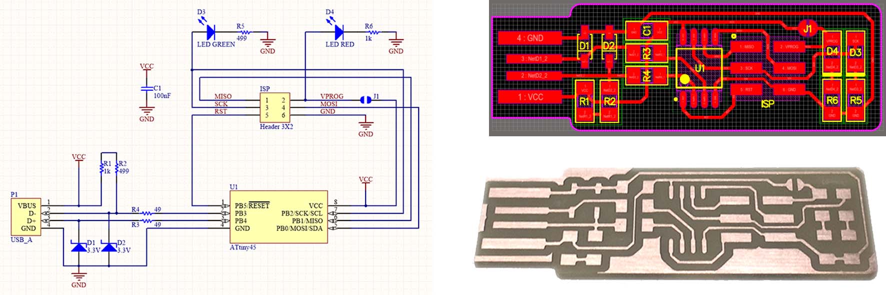
PCB stands for "Printed Circuit Board." A PCB is a thin board made of fiberglass, composite epoxy, or other laminate material. Conductive pathways are etched or "printed" onto board, connecting different components on the PCB, such as transistors, resistors, and integrated circuits.

Machines Used
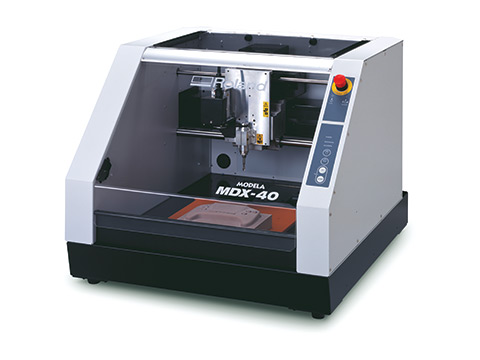
The main machine used in this week's assignment is the Desktop CNC Machine.

  • The Roland MDX-40 was used for cnc milling the coper board in this assignment. This Roland MDX-40 uses the a Computer Controlled Router to Mill the intended object.

Characterize the design rules for your PCB production process

The machine used: Roland MDX-40

Roland mdx-40

The idea is to understand the different settings of the CNC milling process that could affect the output products. There are many variables in the Milling process setting that could be changed and respectively affect the output of the machine. The settings are:

  1. RPM of Milling Bit is the variable that controls the rotating speed of the milling bit.
  2. Mrilling Bit Diameter is the variable that is directly related to the bit diameter. The bigger the diameter, the less we can achieve thin connecting lines.
  3. Feed Rate is the variable that controls the rate the milling bit moves on the surface of the copper board. Milling the inner lines requires a normal feed rate. However, milling the outer parameter of the pcb required very slow feed rate.
  4. Offset Number is the variable that controls the number of passes the milling bit does over the same path. This setting majorly affects the final product. Paths that are not cut in the first pass most probably will be cut during the other passes.

We started by a Test File we got from the internet, that has different paths of various thicknesses. We tested milling this image using the milling bit of diameter 0.15mm.
The test file was downloaded from the following Link

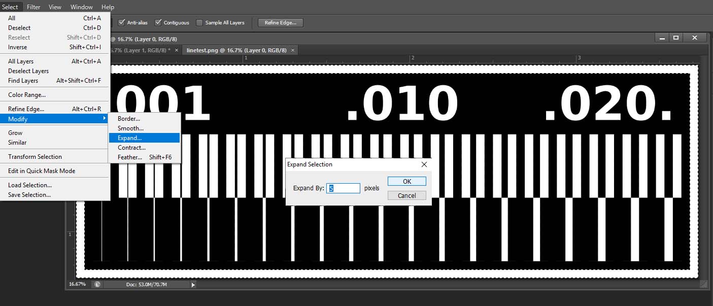
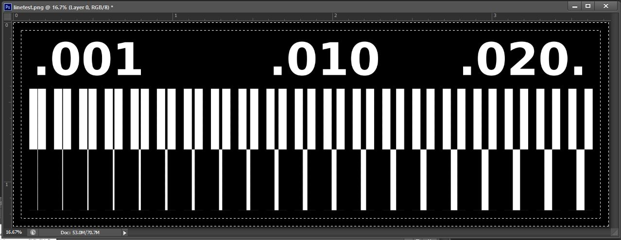
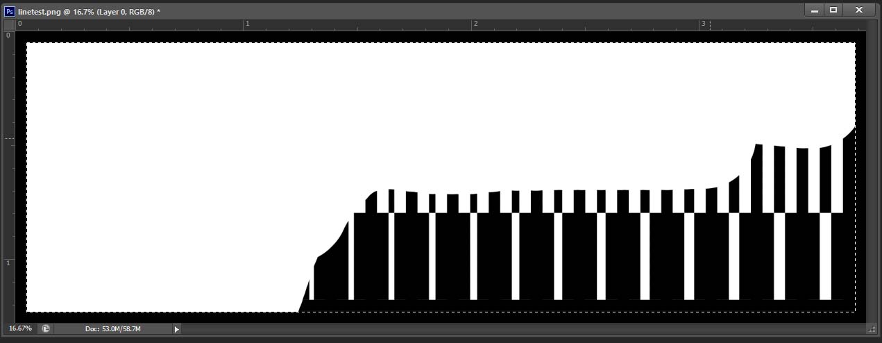
Before milling the test file we had to create 2 images, one for the internal traces and one for the outline cutout.For that we did the following:

  1. Open the file in Photoshop, and select the white border by the magic wand tool then go to select /expand and hit 5 pixels.Then use the brush tool to paint the selection in black. We did this to make sure that the selection is bigger than the white border and there is no gap between the new black and the old black in the center.
  2. test1 test2
  3. Now we will save it as the Inernal Traces.
  4. We open the original file (the one that was downloaded) and select the white border , paint it in black then we select inverse to select the other part and paint it in white making sure there is no black part left.
  5. test3
  6. Now we will save it as the Outline Cutout.
You can download these images from the following links:
  1. Interal Traces
  2. Outline Cutout

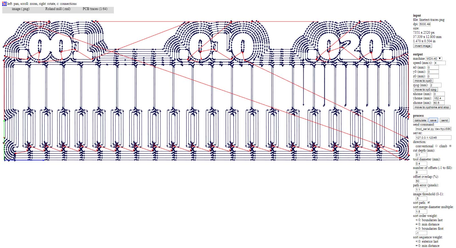
Now we will calculate the g-code for these images

test4 test5 
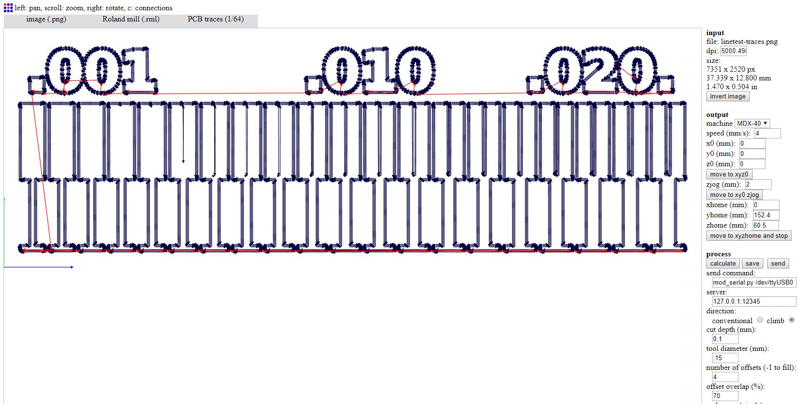
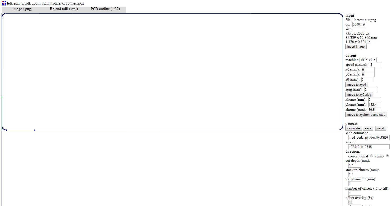
You can download the g-code used for the test from the following links:
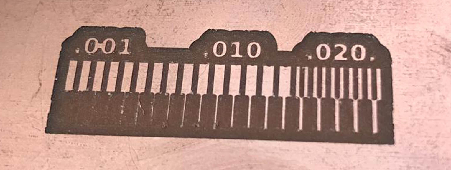
  1. Linetest Traces
  2. Linetest Outline Cutout

The results:

test4 test5

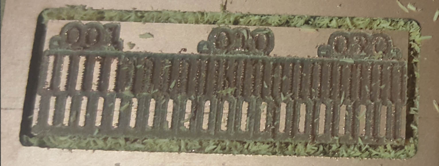
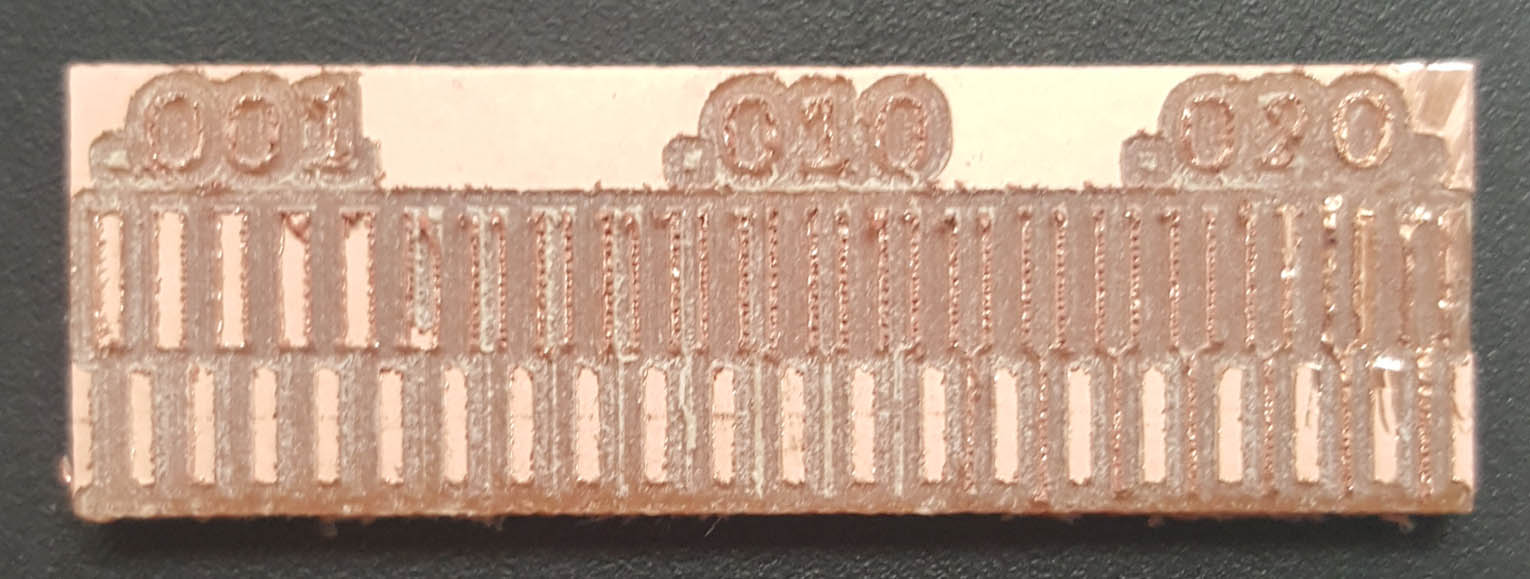
The result are not very satisfying, so we decided to do another test with another milling bit diameter 0.4mm instead of 0.15mm
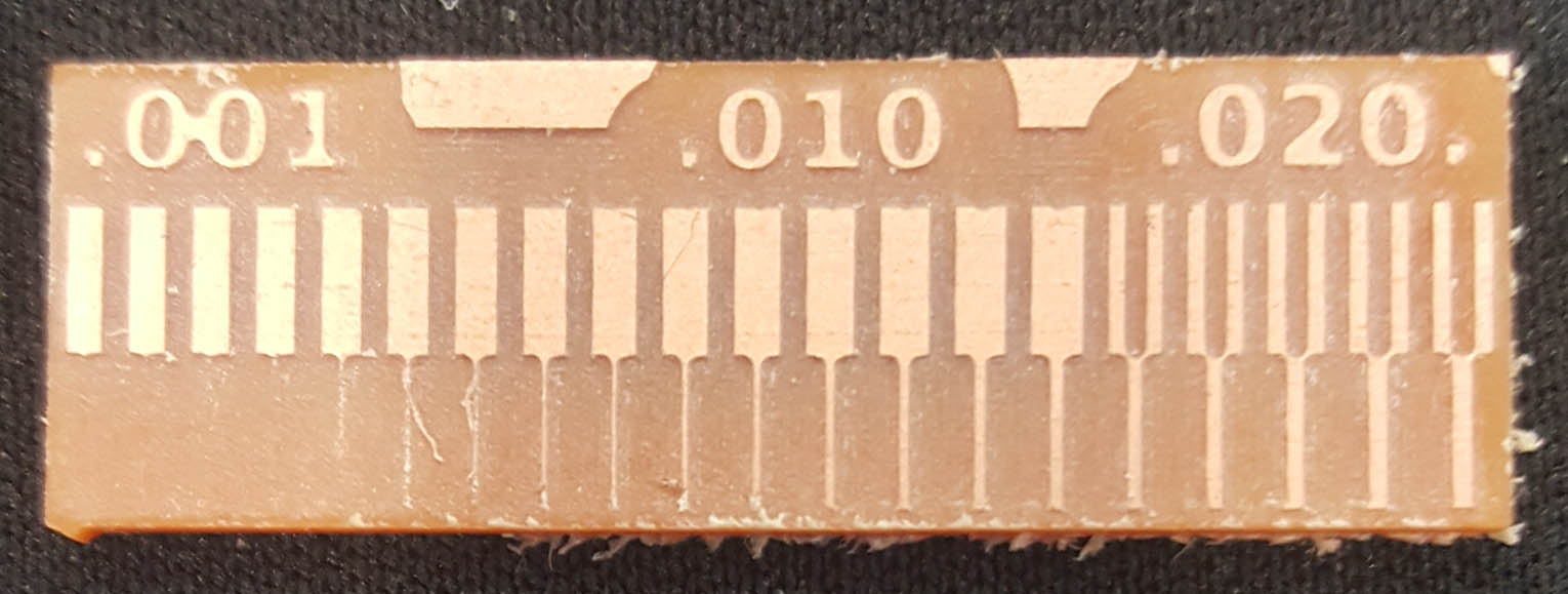
The new g-code:

test4

The new results:

test milling test milling