Computer Controlled Cutting
So the objective of the third week is to discover the various equipment and technologies used for cutting digital designs into various material. There are many different Computer Controlled (CNC) machines available that are used for cutting into a wide range of material. However, we tested only two technologies in this assignment, the Laser Cutter and the Vinyl Cutter.
Group Assinment
The group assginment was to characterize the laser cutter we have in the lab and make test parts that vary in the cutting settings and dimensions.The students were supposed to characterize your lasercutter's focus, power, speed, rate,
kerf, and joint clearance.
Numerical control (NC) (also computer numerical control (CNC)) is the automated control of machining tools (drills, boring tools, lathes) and 3D printers by means of a computer. An NC machine alters a blank piece of material (metal, plastic, wood, ceramic, or composite) to meet precise specifications by following programmed instructions and without a manual operator.
Machines Used
The main two machines used in this week's assignment are the Laser Cutter and the Vinyl Cutter.
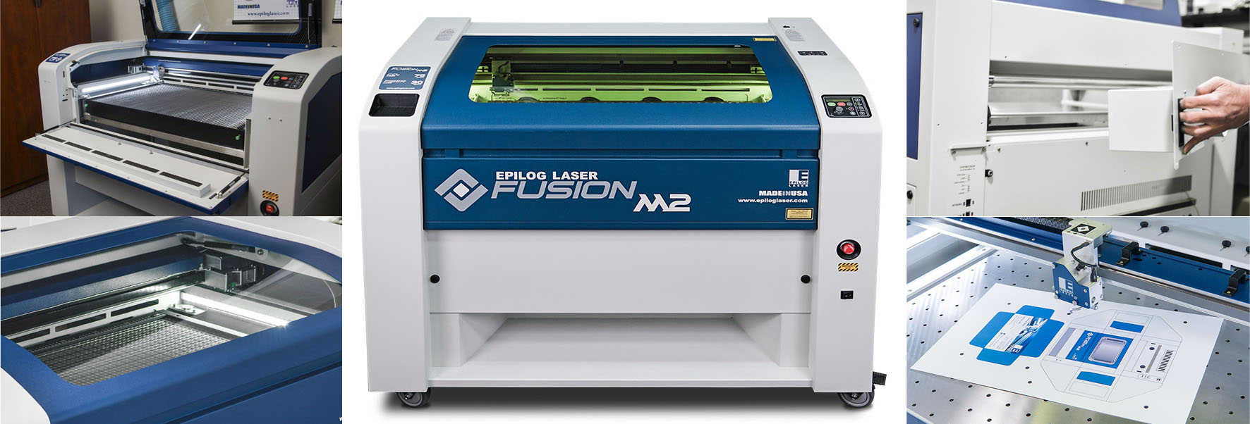
- Epilog Fusion M2 120 Watts was used for laser engraving and laser cutting in this assignment. This Epilog Fusion M2 uses the CO2 Laser Technology to cut and engrave. The laser source is guidged by 2 axis (X and Y) that guide the focal point of the laser where cutting will occur.
- GCC Puma III was used for Vinyl Cutting in this assignment. The Vinyl cutter is a CNC machine that controls a blade that cuts into different soft material, based on a digital design.
Characterize the lasercutter and making test parts
The machine used: Laser Cutter – Epilog Fusion M2
- Work area: 500mm x 800mm
- Materials: wood (12mm), glass, cork, leather, cardboard, paper, fabrics, non-PVC acrylics, and other organic materials (up to 13mm)
- File type: AutoCad, JPG, and BMP for raster.
- Power: 120 Watts
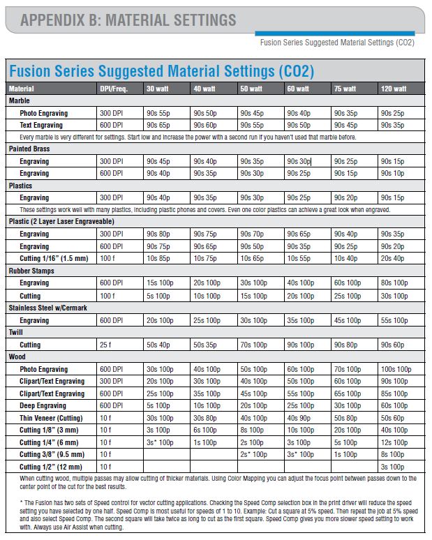
Fusion Series Suggested Material settings for Power, Frequency and Speed:
Material available:
- 3mm MDF -which happened to be of 3.17 mm after measuring it accurately with the calliper
- 5.5 mm MDF
We have used the 3.17mm MDF for the testing
For cutting, the POWER of the laser cutter should always be 100; it varies for engraving.
We calculate the Kerf of our laser cutter via 2 tests:
Kerf is defined as the width of material that is removed by a cutting process. It was originally used to describe how much wood was removed by a saw, because the teeth on a saw are bent to the side, so that they remove more material than the width of the saw blade itself, preventing the blade from getting stuck in the wood.
First test:
- Objective: Select the best cutting settings for a specific material in terms of POWER, FREQUENCY, and SPEED . In the case of wood, the FREQUENCY should be the lowest (10).Cutting SPEED needs to be determined in order to have the smallest kerf.
- Method: Cut multiple lines with different SPEED settings around the reference speed provided by the manufacturer’s specifications. Observe by eye at which speed the material is fully cut. The first fully cut line should be the finest cut, thus the smallest kerf.
Second test:
- Objective: Measure the kerf for the setting previously selected
- Method: Cut one or multiple segments with the same setting. Measure the length of the outer frame, measure the length of the adjacent cut segments, divide the difference by the number of cuts. The result is an estimation of the kerf. We made two tests with different layouts to get an average.
How to perform the tests:
- First: Drawing a test layout.
- Draw a layout on a vector type CAD (we used AutoCAD). Make sure there is no line superposition to avoid cutting the same line twice. The lines that should be cut in a single cut with same parameter should be joined into one line. (Click ‘Ctrl + A’ then ‘Join’)
- Save as DXF 2007
- Import DXF file in Corel Draw. Make sure all the lines are hairline (hairline will be cut; other lines will be engraved). Place the drawing in top left corner.
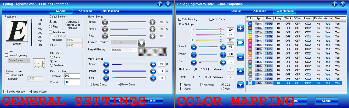
- Open the laser cutter properties window (Ctrl + P for printing the job). In the general tab select vector job type, in the layout tab select top left corner for positioning, enter machine bed dimensions (800x500 mm for our machine)
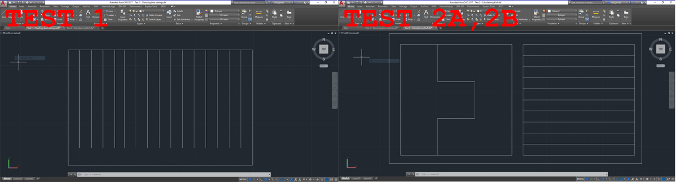
- Second: Colour mapping (for Test 1 only):
- Colour mapping helps in feeding different settings for each different line, so that the laser cutter understands that it should not cut all the lines in the same way or speed
- In Corel Draw, colour each line with a different colour and note the RGB of each colour.
- In the laser cuter properties window, open the colour mapping tab, copy the RGB previously noted and assign cutting parameters for each colour, specifying speed, power, and frequency (in %).
- For wood, the power will remain at 100%, and the frequency at 10% according to the manufacturer’s specifications. So in this case only speed will vary.
- According to manufacturer’s specification, the reference speed value for wood is 40%. So the speed setting will have to range around this value.
- Select vector and deselect raster to cut and not engrave (it shouldn’t make a difference if all the lines are hairlines).
- Third: Operating the laser cutter.
- Turn on the machine, then load the file to the laser cutter by clicking print. From there, the work is on the laser cutter interface.
- Position the wood board on the laser cutter metal bed. Then place the gage tool to calibrate the focal point of the laser on the right Z value. When the gage touches the board, zero Z. Then move the laser cutter head to the starting position and zero XY
- Before starting, make sure that the compressor is turned on, as well as the extractor, to enable air flow to evacuate the fumes and prevent fire risks and toxic fumes inhalations.
- Start cutting, and supervise the machine till the job is completed (the laser cutter should not be left without supervision while operating).
- Once the job is done, wait for fumes to be fully evacuated before removing the board.
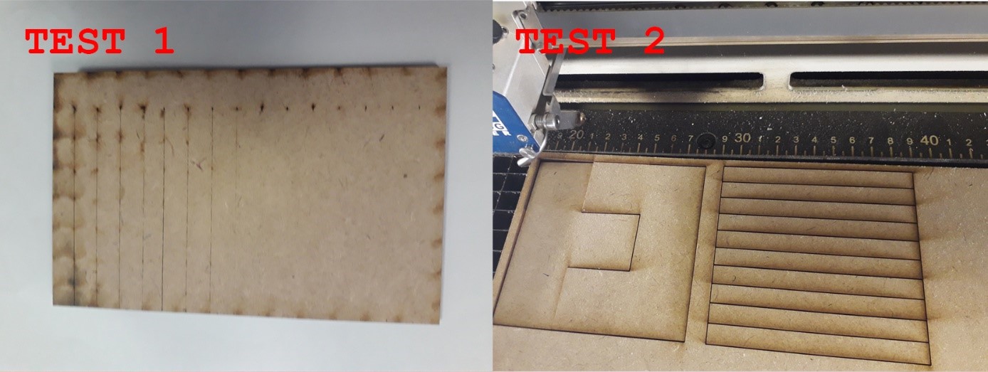
Test results:
- First test:
The best cut appears to be between 28 and 30% speed
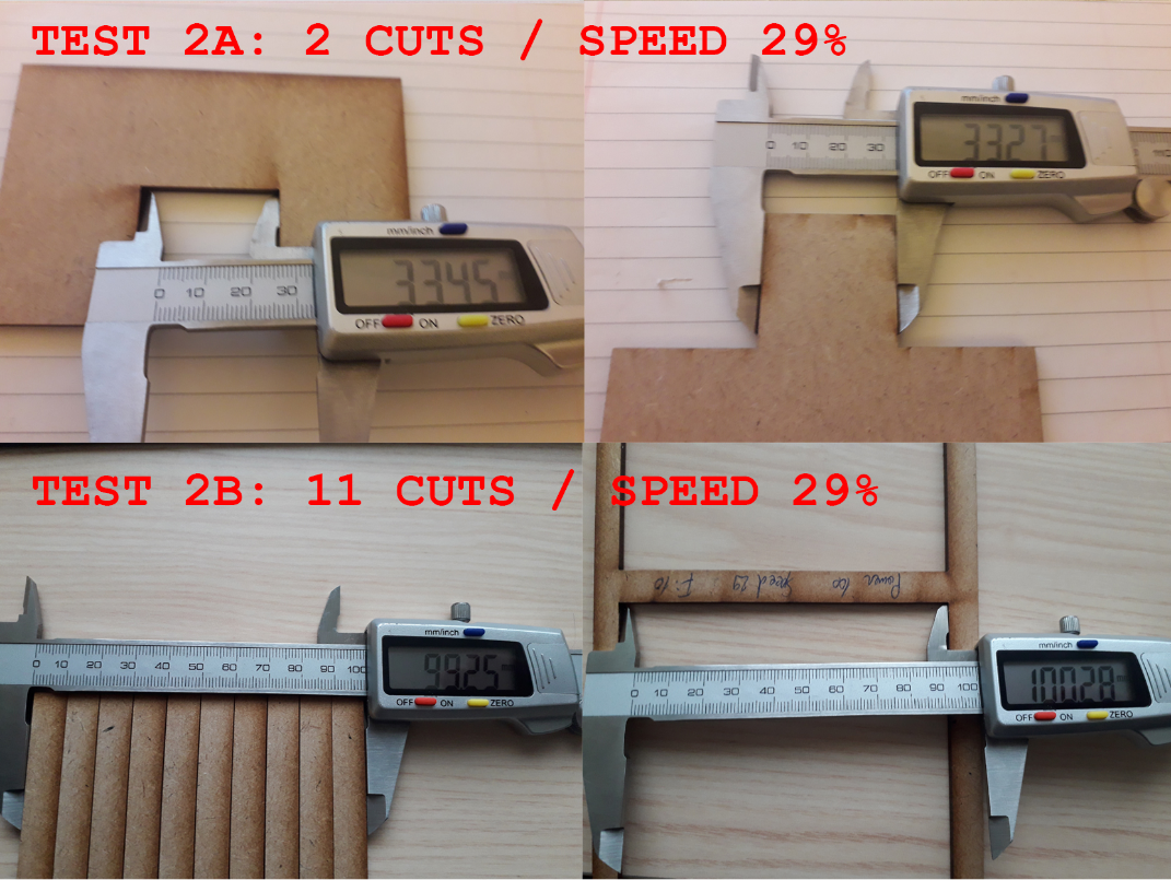
- Second test:
I- Evaluation of the kerf for speed 29%
a. Test 2A: Kerf = (33.45 - 33.27) / 2 = 0.090
b. Test 2B: Kerf = (100.28 - 99.25) / 11 = 0.094
 II- Evaluation of the kerf for speed 30%
a. Test 2A: Kerf = (33.81 – 33.73) / 2 = 0.04
b. Test 2B: Kerf = (100.34 – 99.88) / 11 = 0.042
Test results 5.5mm:
- First test:
The best cut appears to be between 13% speed
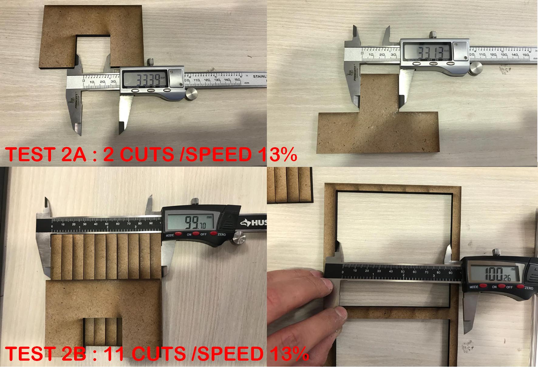
- Second test:
I- Evaluation of the kerf for speed 13%
a. Test 2A: Kerf = (33.39 - 33.13) / 2 = 0.13
b. Test 2B: Kerf = (99.90 - 99.40) / 11 = 0.05