11 - Output Devices
Individual Assignment
Charlieplexing
For this week I decided to continue working on my final project. The idea is to have a LED matrix that lights up in the neck to show which notes have to be played, so I decided to try the Charlieplexing method to light a lot of LED's with only some pins. I found this technic really interesting and I wanted to know more aout it.
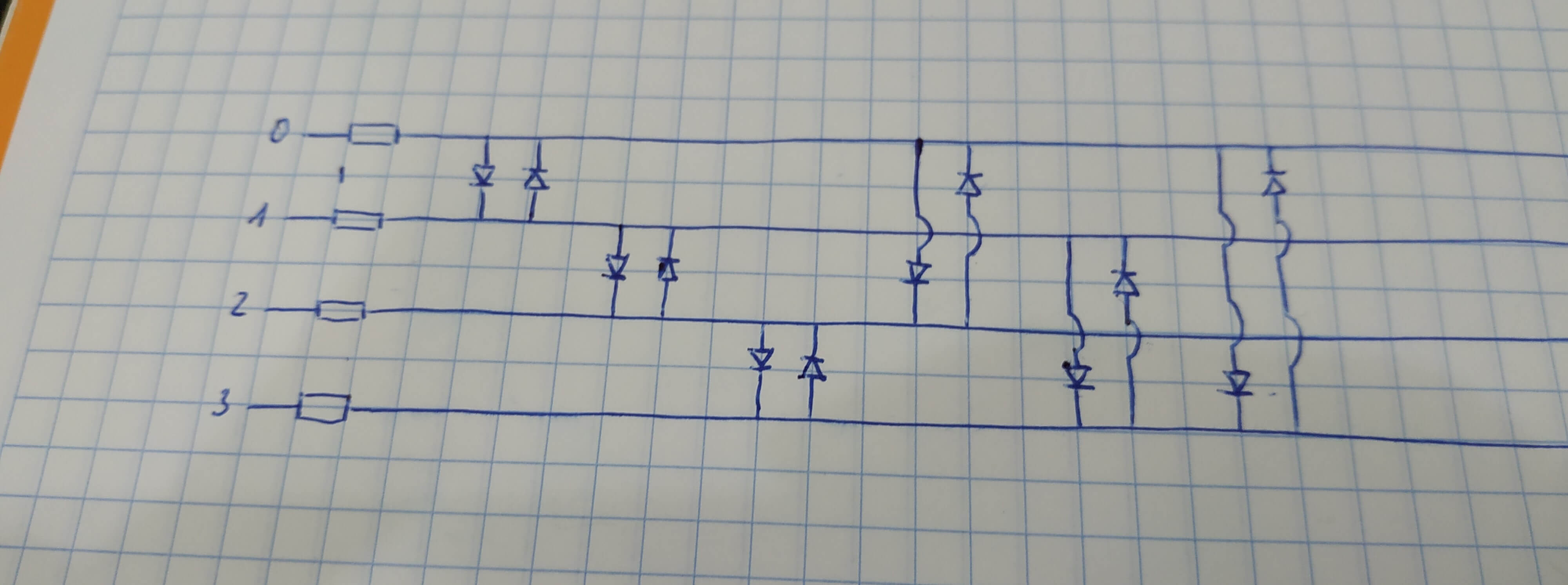
The idea of Charlieplexing is to light a full matrix of LED's using few I/O pins of a microcontroller by changing the direction of the current between pins, defining them as inputs and outputs. Connecting 2 LED's between 2 pins, but with different orientation in paralel, allows to light one in one direction of the current and the other one in the other direction. The formula that follows this method is that we can light n*(n-1) LED's, beeing n = number of pins. In the following image you can see that with 4 pins we can light up to 12 LED's.
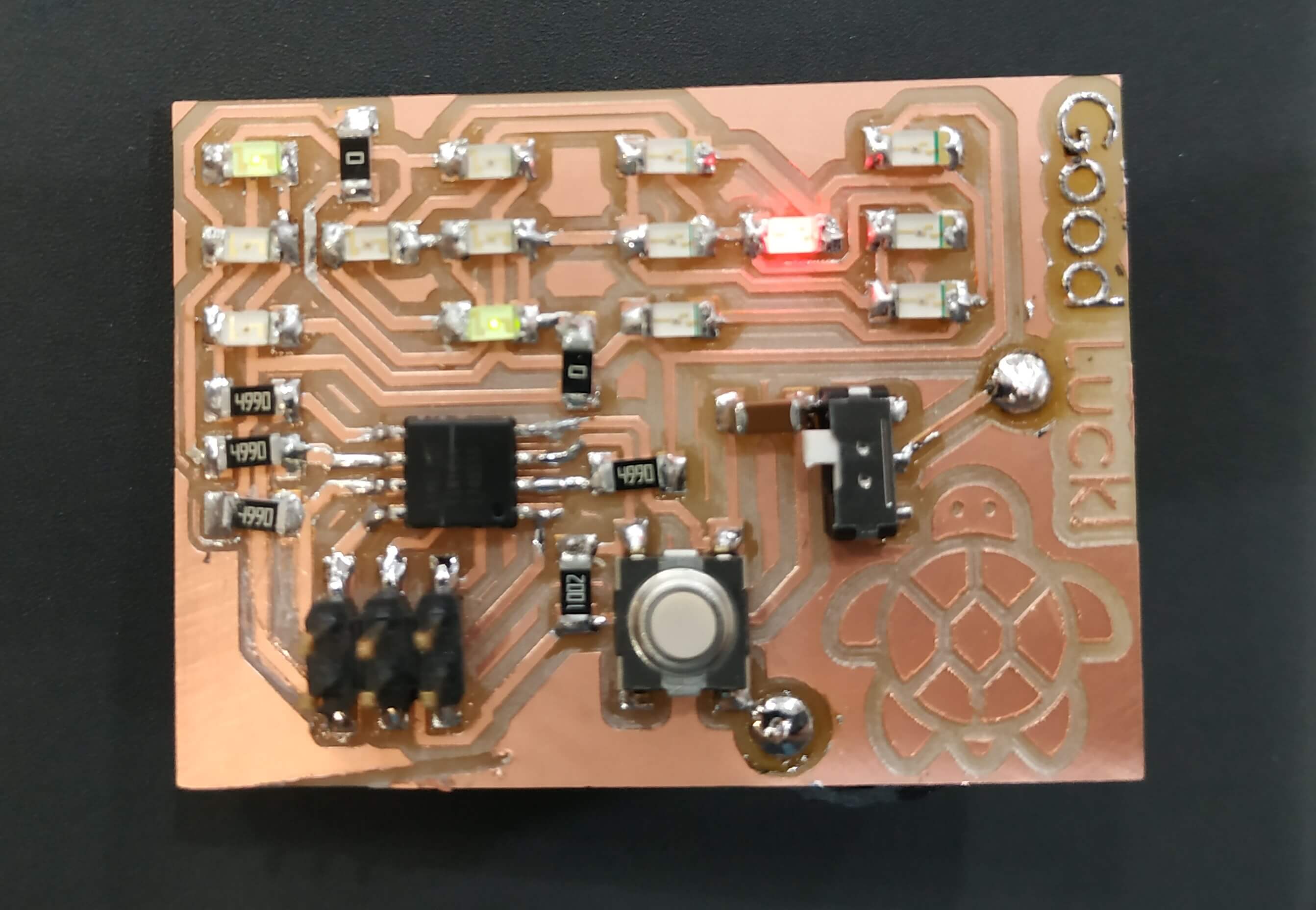
Before trying to do the full panel that I want for the final project I decided to test this method with a simple example. I didn't wanted to do a useless board with 6 LED's, so, after spending some time in the internet looking for inspiration and ideas, I grabed Emily Hammes idea from his website to create a board that simulates 2 dices. I only grabbed the idea, I redesigned the board and it's components.
I found this project really interesting because it uses the Charlieplexing technic, but also shows that with few pins you can do a lot of things. We are capable of light 14 LED's, 7 LED's for each dice and we have 2 in our board, with only 4 pins. This seems impossible as the Charliplexing rule is that we can only light n*(n-1) LED's, so with four pins we only can light 12 LED's. But note that for our application we can join LED's by pairs and light up the pair instead of only one of them, because there are combinations that didn't exist in a real dice.
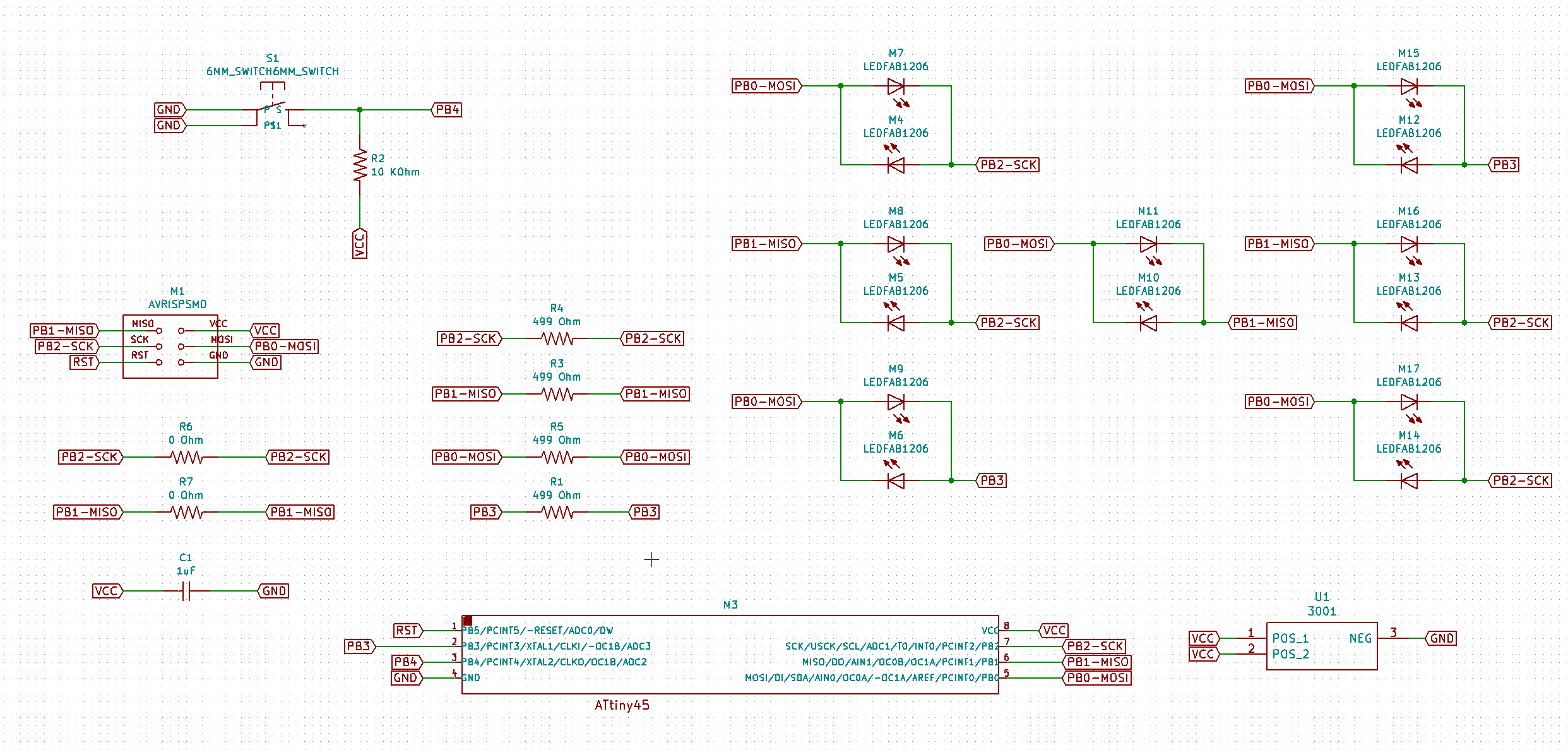
Schematic
I keep using KiCad to design my boards as it is Open Source and I prefer it than Eagle. For this project I used an Attiny 45 because I wanted to have a little microcontroller and it has the exact amount of available I/O pins that I need, 4 for the Charlieplexing and 1 for a button. I connect a resistor to each pin to protect the LED's and also a condensor between the VCC and the GND as usual as an energy resrve. This is the list of components and the Schematic:
- 1x Attiny 45
- 1x 1uF Capacitor
- 7x Green LED
- 7x Red LED
- 1x Tactile Button
- 4x 499Ω Resistor
- 1x Coin Battery Holder
- 1x 2x3 ISP Connection
- 2x 0Ω Resistor (as jumpers)
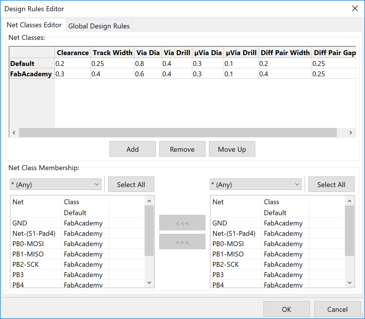
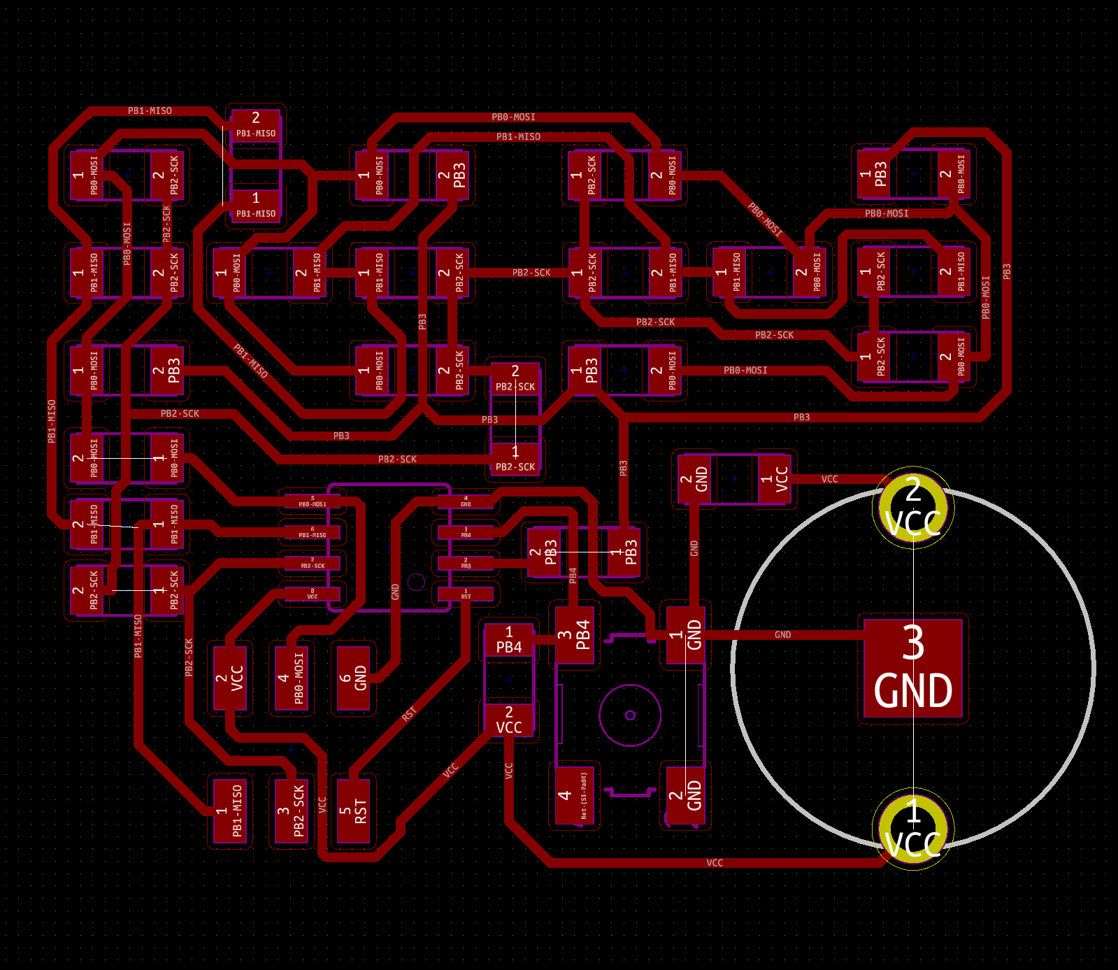
Traces Design
This is allways the most dificult part. It is a really hard process to get the correct traces without using jumpers. Finally I used 2 jumpers to make it easier. KiCad is a really good program, but you have to get use to it, I did the routing 3 times for stupid mistakes. First I did a very large version to see it clear, but I wanted to keep it small and, as the traces can not be scaled all together, I had to repeat the process but in a smaller version. Also check you have the correct design rules, because this second time I did it with the default rules and I get really thin traces so I had to re-do it.
Also, it is a really common error to have some paths joined in the milling machine, so be carefull when you calculate the machine coordinates in Mods, and make sure everything is correct. I did some ajustments a few times until I get the final design.
NOTE: This version is the final one, I correct some errors I had when I saw them soldering, this version didn't need the jumper wires that I will explain now.
Creating the traces and outline cut and milling
For this process I allways use Inkscape. First I exported the board as SVG and import it to Inkscape. There is really easy to invert the colours, create an outline and, for this project, create the holes for the battery holder.


NOTE: If you use the same method than me, Invert the image of the Holes in Mods to have the cprrect result.
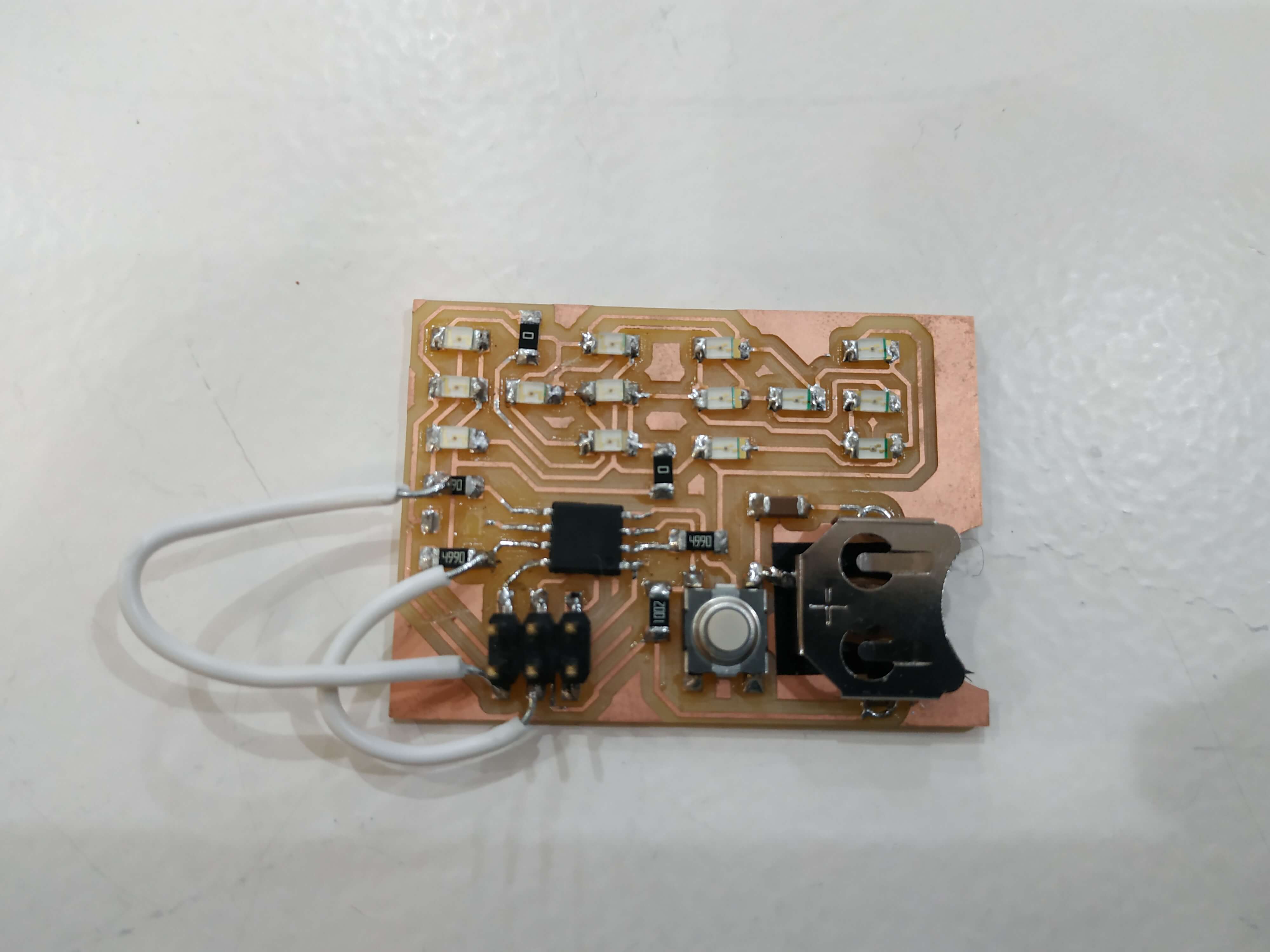
Errors
After soldering the board I realize that I did a huge mistake. I connected the MISO and the SCK ports of the ISP after the resistor of each pin. I wasm't able to program it like that, so I had to solder a pair of ugly jumpers, but it was the fastest solution to see if the design was working. Soldering one of them I had a problem and a piece of copper jump off the board, so I stick a piece of vynil copper papper and solder it again. Finally I realize I had to paths joined, so I cut them with a cutter knife.
Finally, when all was up and running I realized that I had the wrong battery holder. I used a 12 mm coin battery holder, but it is for 1.5V batteries. I need at least 3.3V, so I changed the finall design to have a 3.3V battery at the back.
NOTE: All this errors are solved in the new design and the new traces didn't need those jumpers.
Program
To keep it simple I decided to use the Arduino IDE to program the board. The idea of this program is really simple, each time that the button is pressed two new values are create by a random generator btween 1 and 7 (7 not inclusive) and shown in the dice display. The random seed is generated by the time spend until the first press of the button.
int wait = 1;
int RandomState = 1;
int PrevButtonState = 0;
int left = 0;
int right = 0;
void setup() {
pinMode(4,INPUT);
}
void loop() {
if (RandomState == 0) {
left = random(1,7);
delay(10);
right = random(1,7);
delay(10);
RandomState = 1;
}
if ((digitalRead(4) == LOW) & (PrevButtonState == 0)) {
RandomState = 0;
PrevButtonState = 1;
randomSeed(micros());
delay(10);
}
if ((digitalRead(4) == HIGH) & (PrevButtonState == 1)) {
PrevButtonState = 0;
delay(10);
}
showL(left);
showR(right);
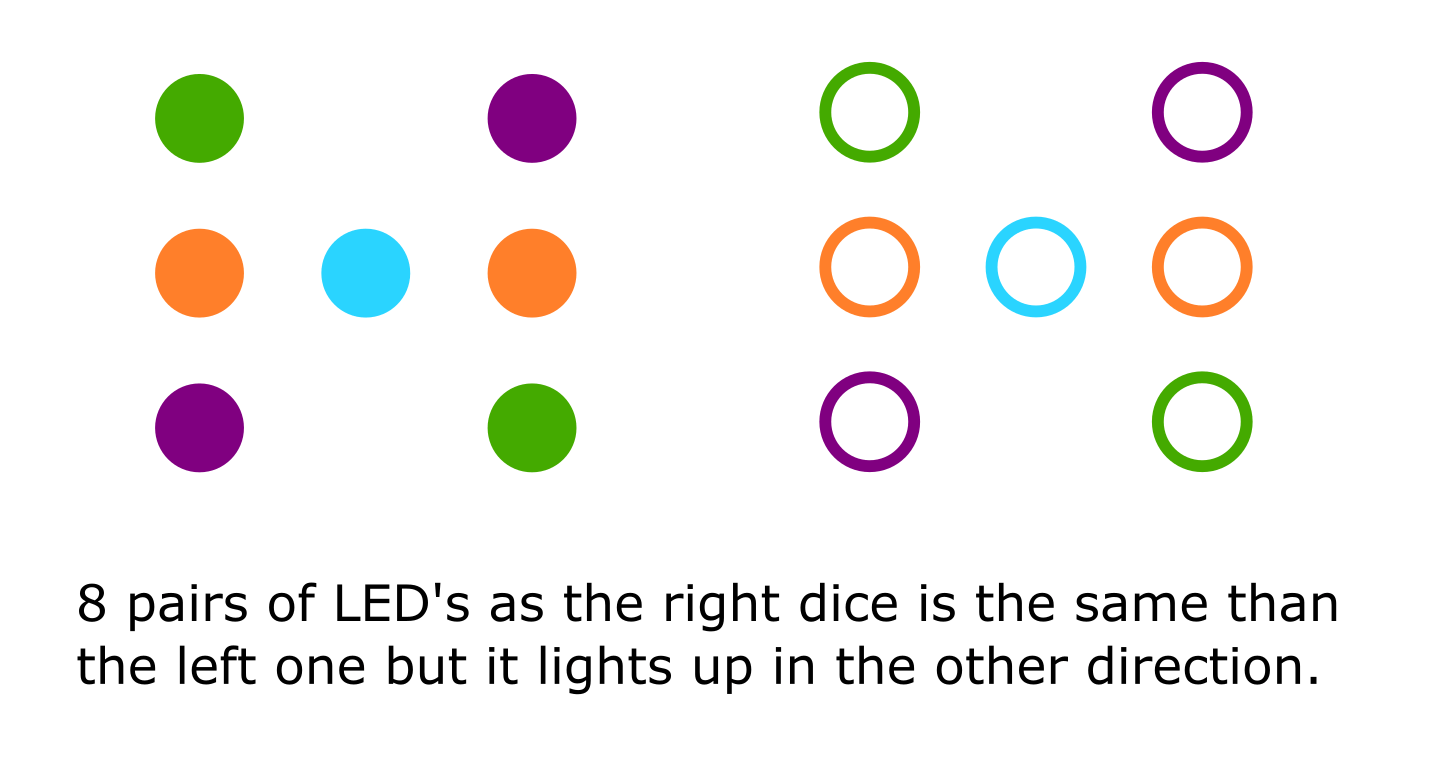
}To do it I defined a lot of little functions, first to define how to light the different pair of LED's. To do it I number them from one to eight and create a function to light them defining the non related pins as INPUTS and the related pins to OUTPUS as high or low depending on the dice. This is an image of the numbers:
void one(){
  pinMode(0,OUTPUT);
  digitalWrite(0,HIGH);
  pinMode(1,OUTPUT);
  digitalWrite(1,LOW);
  pinMode(2,INPUT);
  pinMode(3,INPUT);
}

void two(){
  pinMode(0,OUTPUT);
  digitalWrite(0,HIGH);
  pinMode(2,OUTPUT);
  digitalWrite(2,LOW);
  pinMode(1,INPUT);
  pinMode(3,INPUT);
}

void three(){
  pinMode(0,OUTPUT);
  digitalWrite(0,HIGH);
  pinMode(3,OUTPUT);
  digitalWrite(3,LOW);
  pinMode(1,INPUT);
  pinMode(2,INPUT);
}

void four(){
  pinMode(1,OUTPUT);
  digitalWrite(1,HIGH);
  pinMode(2,OUTPUT);
  digitalWrite(2,LOW);
  pinMode(0,INPUT);
  pinMode(3,INPUT);
}

void five(){
  pinMode(0,OUTPUT);
  digitalWrite(0,LOW);
  pinMode(1,OUTPUT);
  digitalWrite(1,HIGH);
  pinMode(2,INPUT);
  pinMode(3,INPUT);
}

void six(){
  pinMode(0,OUTPUT);
  digitalWrite(0,LOW);
  pinMode(2,OUTPUT);
  digitalWrite(2,HIGH);
  pinMode(1,INPUT);
  pinMode(3,INPUT);
}

void seven(){
  pinMode(0,OUTPUT);
  digitalWrite(0,LOW);
  pinMode(3,OUTPUT);
  digitalWrite(3,HIGH);
  pinMode(1,INPUT);
  pinMode(2,INPUT);
}

void eight(){
  pinMode(1,OUTPUT);
  digitalWrite(1,LOW);
  pinMode(2,OUTPUT);
  digitalWrite(2,HIGH);
  pinMode(0,INPUT);
  pinMode(3,INPUT);
}
Then I created functions to show the real numbers from 1 to 6 for each dice, beeing R the right and L the left one. When more than one pin has to be light up it is really usefull to set a small delay between the diferent changes that will be imperceptible for the human eye. Each number has a function, so I Created a new one to show the numbers depending on the random generated number.
void L1() {
  one();
  delay(wait);
}

void R1() {
  five();
  delay(wait);
}

void L2() {
  two();
  delay(wait);
}

void R2() {
  six();
  delay(wait);
}

void L3() {
  one();
  delay(wait);
  three();
  delay(wait);
}

void R3() {
  five();
  delay(wait);
  seven();
  delay(wait);
}

void L4() {
  two();
  delay(wait);
  three();
  delay(wait);
}

void R4() {
  six();
  delay(wait);
  seven();
  delay(wait);
}

void L5() {
  one();
  delay(wait);
  two();
  delay(wait);
  three();
  delay(wait);
}

void R5() {
  five();
  delay(wait);
  six();
  delay(wait);
  seven();
  delay(wait);
}

void L6() {
  two();
  delay(wait);
  three();
  delay(wait);
  four();
  delay(wait);
}

void R6() {
  six();
  delay(wait);
  seven();
  delay(wait);
  eight();
  delay(wait);
}

void L0() {
  one();
  delay(wait);
  two();
  delay(wait);
  three();
  delay(wait);
  four();
  delay(wait);
}

void R0() {
  five();
  delay(wait);
  six();
  delay(wait);
  seven();
  delay(wait);
  eight();
  delay(wait);
}

void showL(int L) {
  if (L == 1) {
    L1();
  }
  if (L == 2) {
    L2();
  }
  if (L == 3) {
    L3();
  }
  if (L == 4) {
    L4();
  }
  if (L == 5) {
    L5();
  }
  if (L == 6) {
    L6();
  }
  if (L == 0) {
    L0();
  }
}

void showR(int R) {
  if (R == 1) {
    R1();
  }
  if (R == 2) {
    R2();
  }
  if (R == 3) {
    R3();
  }
  if (R == 4) {
    R4();
  }
  if (R == 5) {
    R5();
  }
  if (R == 6) {
    R6();
  }
  if (R == 0) {
    R0();
  }
}
Conclusion
Charlieplexing is a really usefull technic and I will use it for sure in my final project as the neck LED's matrix. I would also like to work with more outputs to learn more about them and the options that we have and how they work. It was a really interesting week, and I recommend everybody to learn the Charlieplex tachnic because it can be used in a lot of projects.