experimentation
make it happen
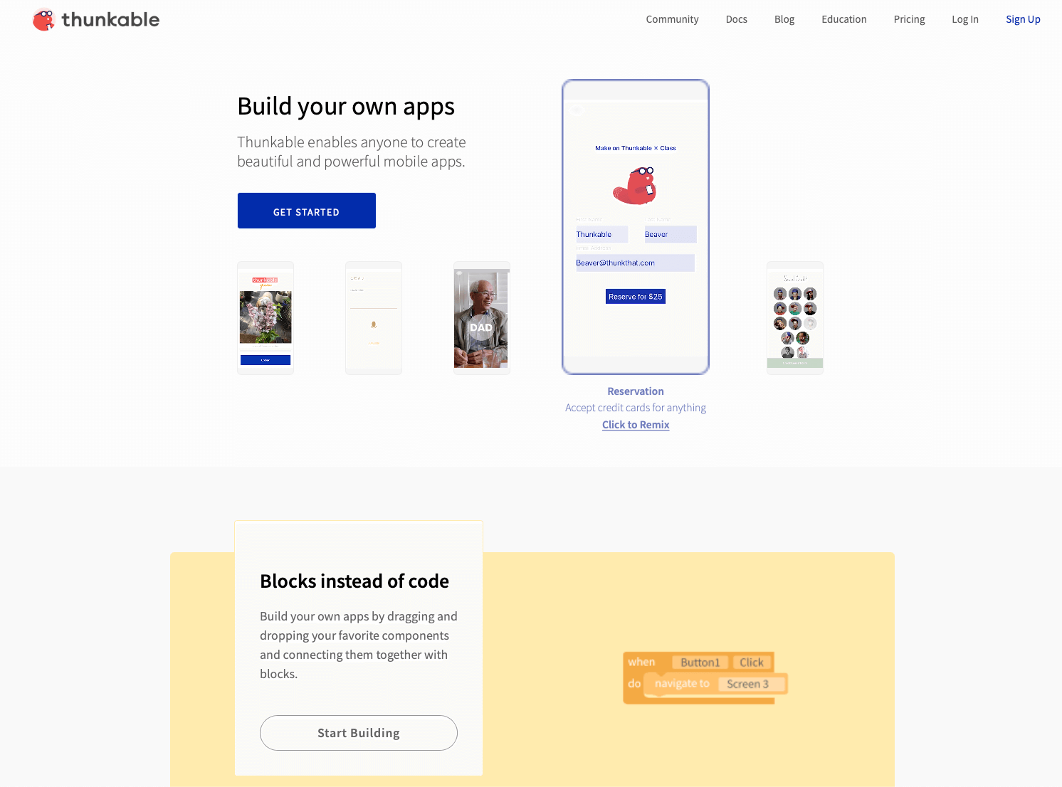
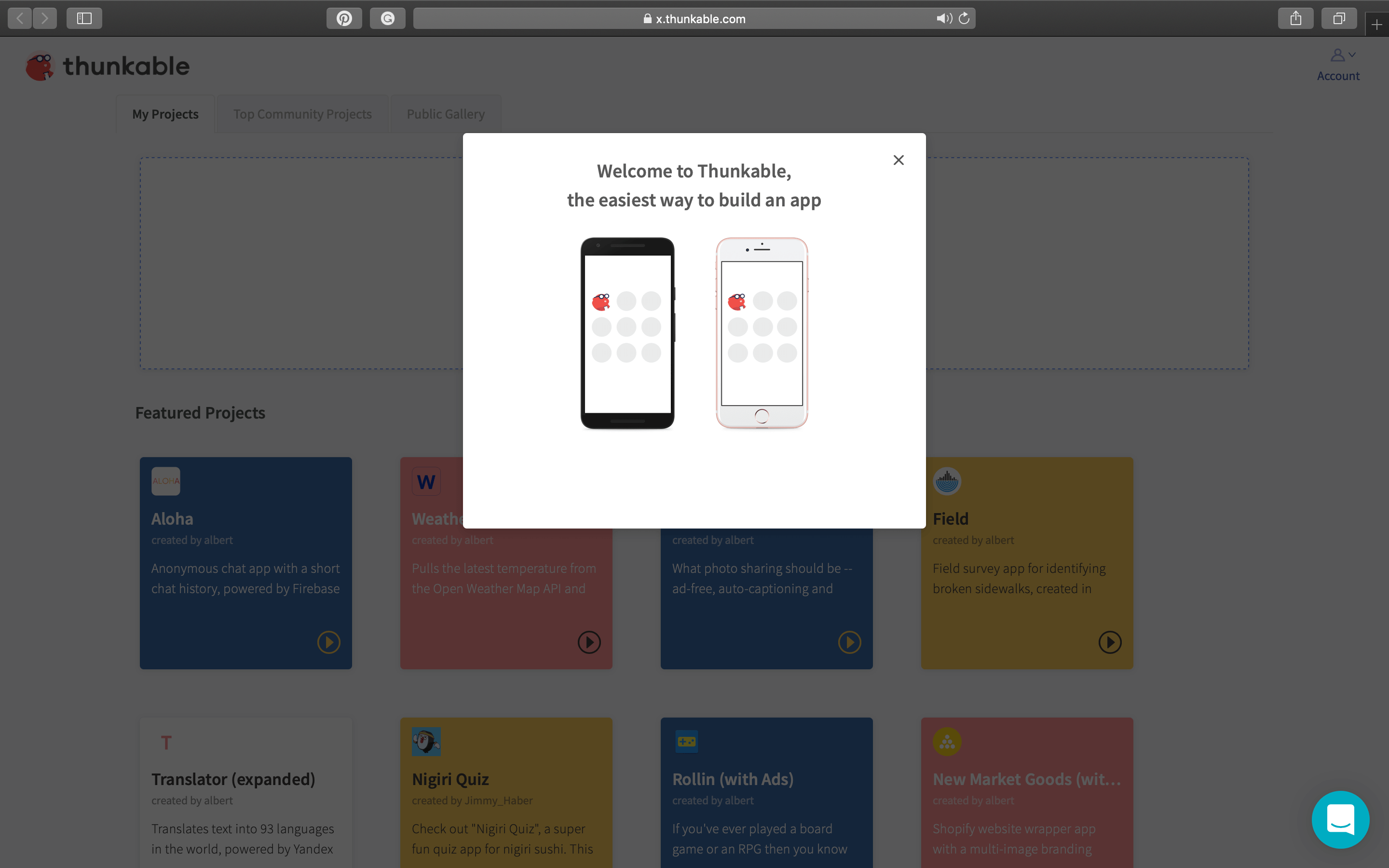
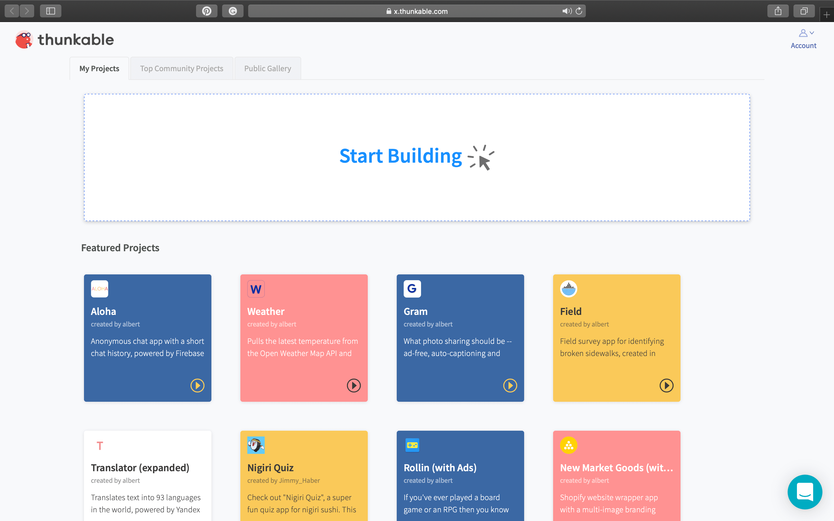
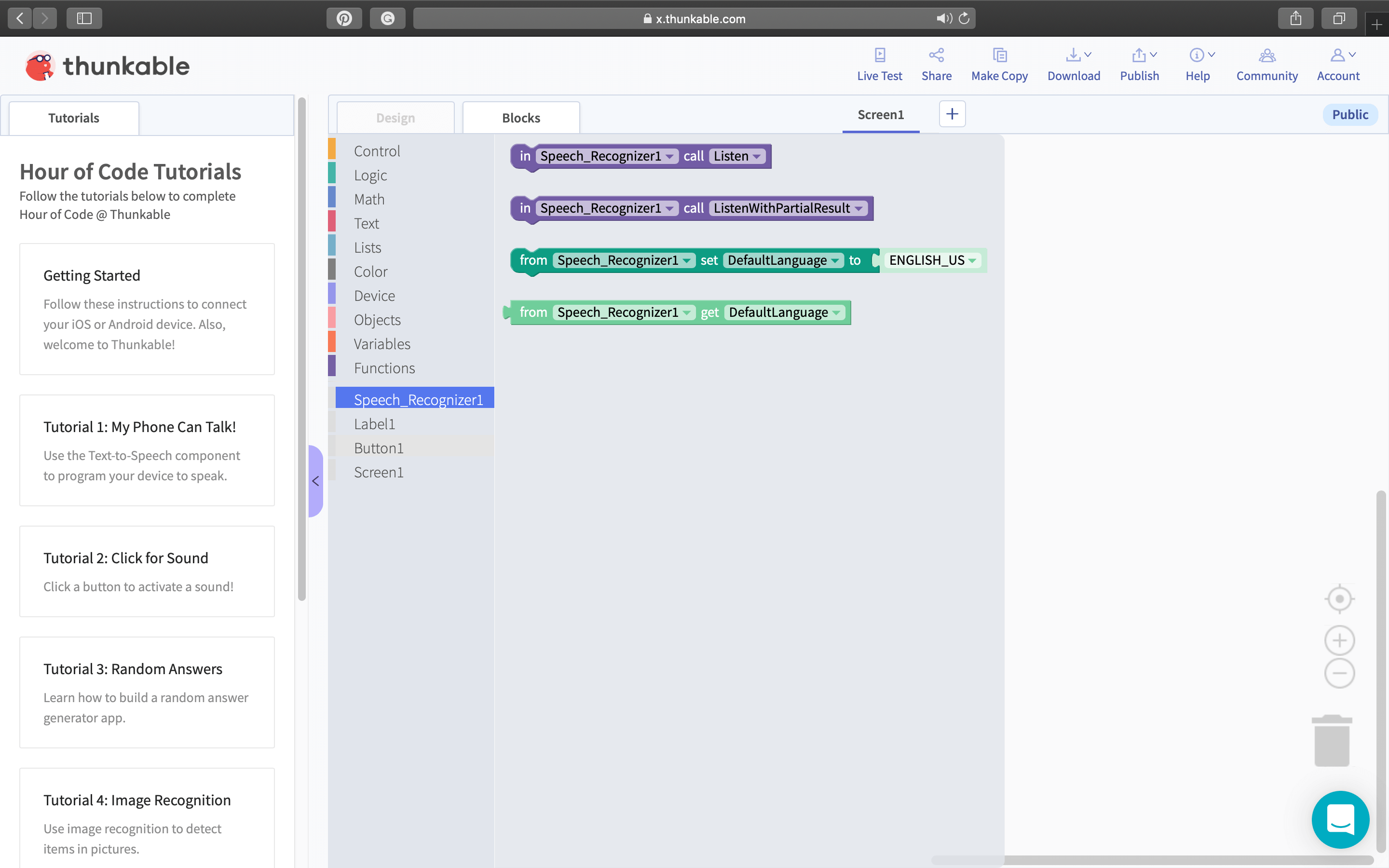
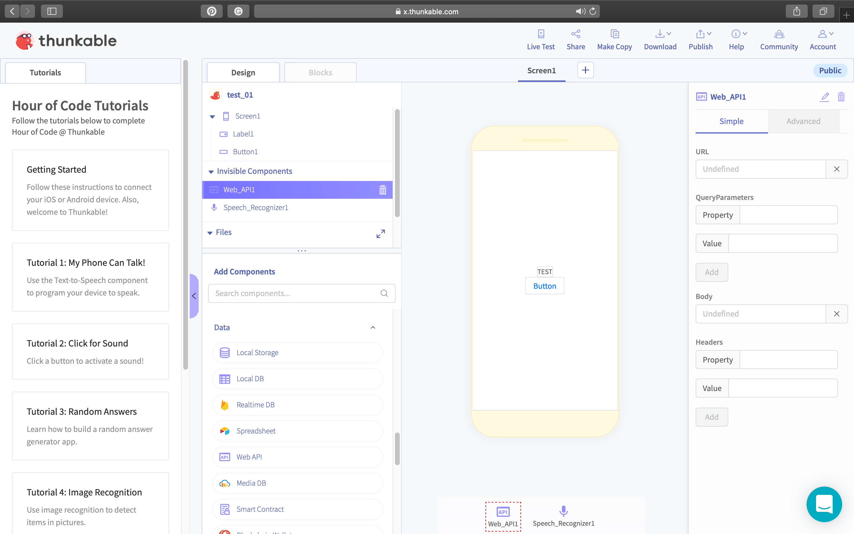
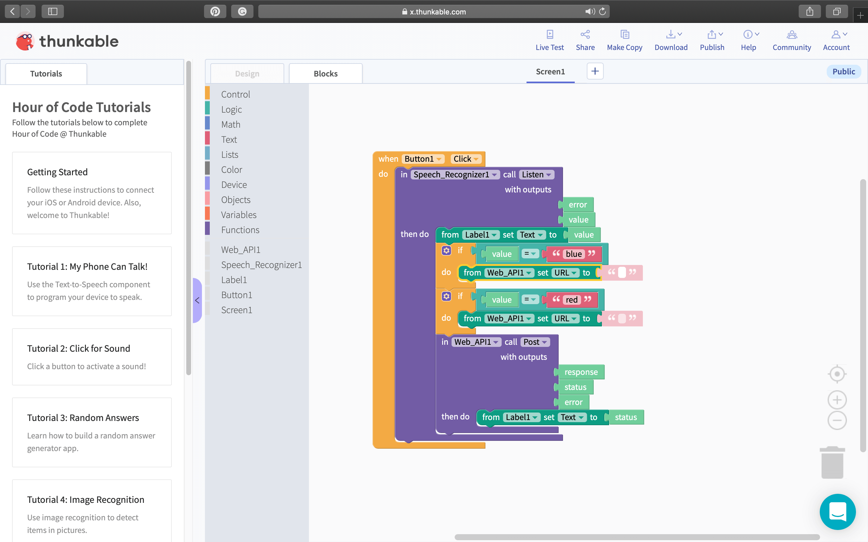
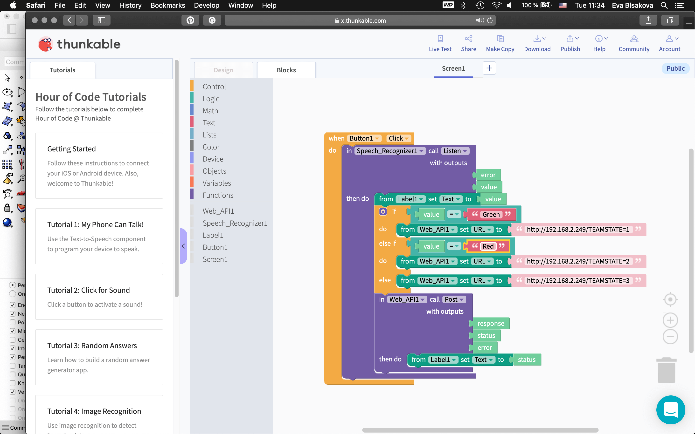
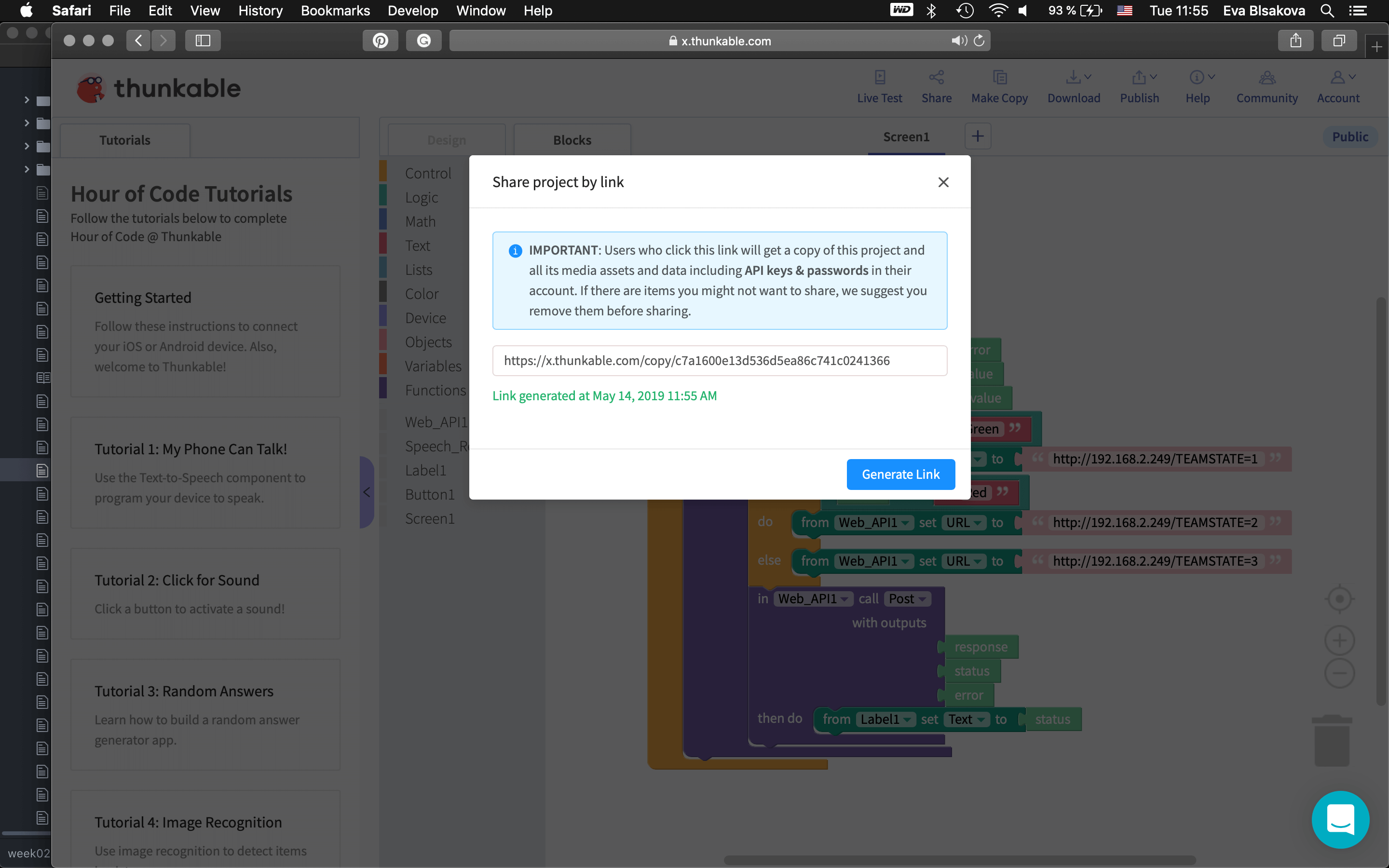
For this weeks assignment I wanted to make an app with what you can control the light color. So I jumped on the https://thunkable.com/#/
#thunkable
#thunkable
#thunkable
#thunkable
#thunkable
#thunkable
#thunkable
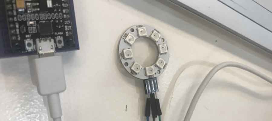
Node MCU v3 with LED Ring connected with micro USB. #testingsetup
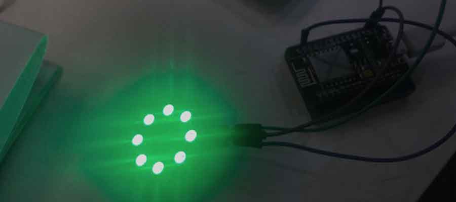
Node MCU v3 with LED Ring connected with micro USB. When I say green you make it light on the green #testingsetup #worked
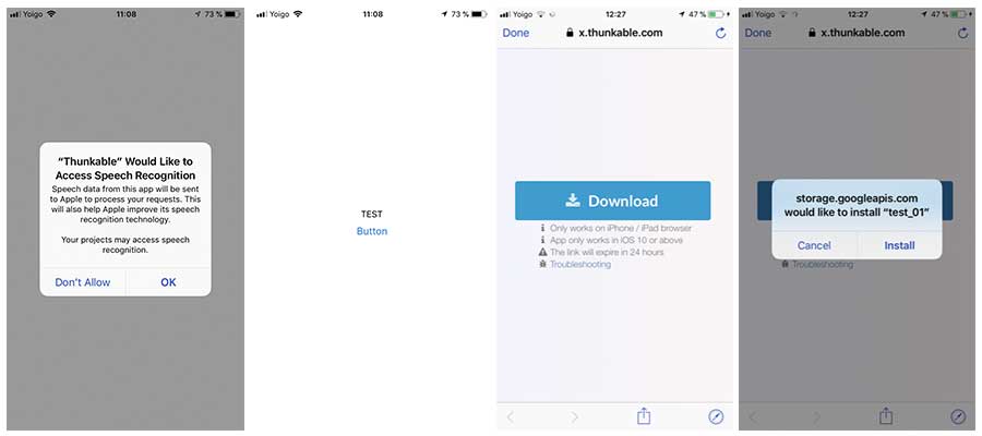
Installing and running Thunkable on the iPhone. #testing
After I wanted to connect it with my final project too, but there was some issue with my Node MCU v3 what I was not able to resolve, so I decided to test simple python script creating an app for on/off of the lamp. I found this example tutorial very useful to follow up. Since I already had installed, arduino, I just connected the board from my final project to my comp. had to list usb port where is it connected by typing following to the terminal:
save python code somewhere and run using
Python code:
Than open Arduino and put there following code:
of course I had to make a changes to it to communicate with my board. so than it looked like that:
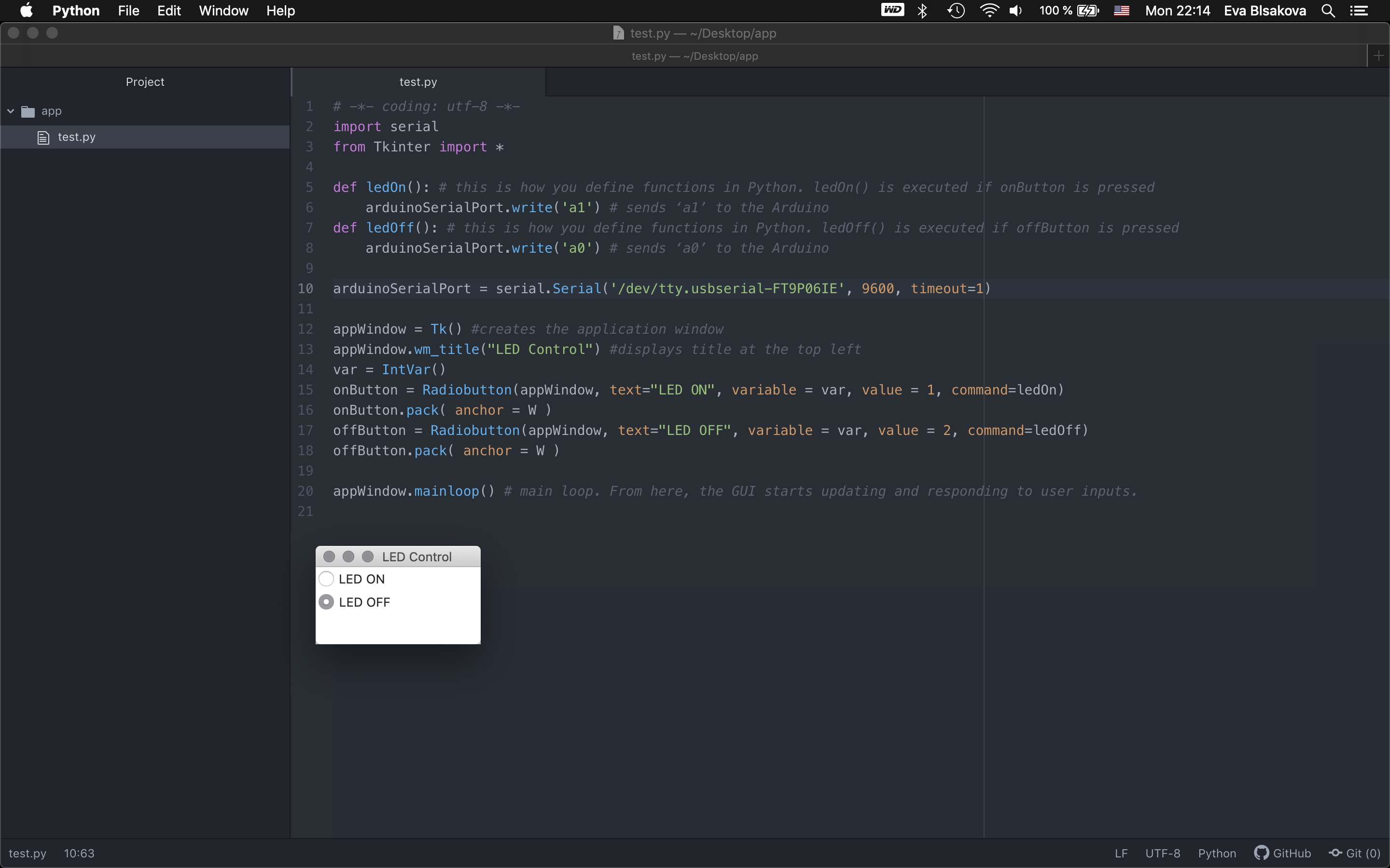
#simple interface with buttons
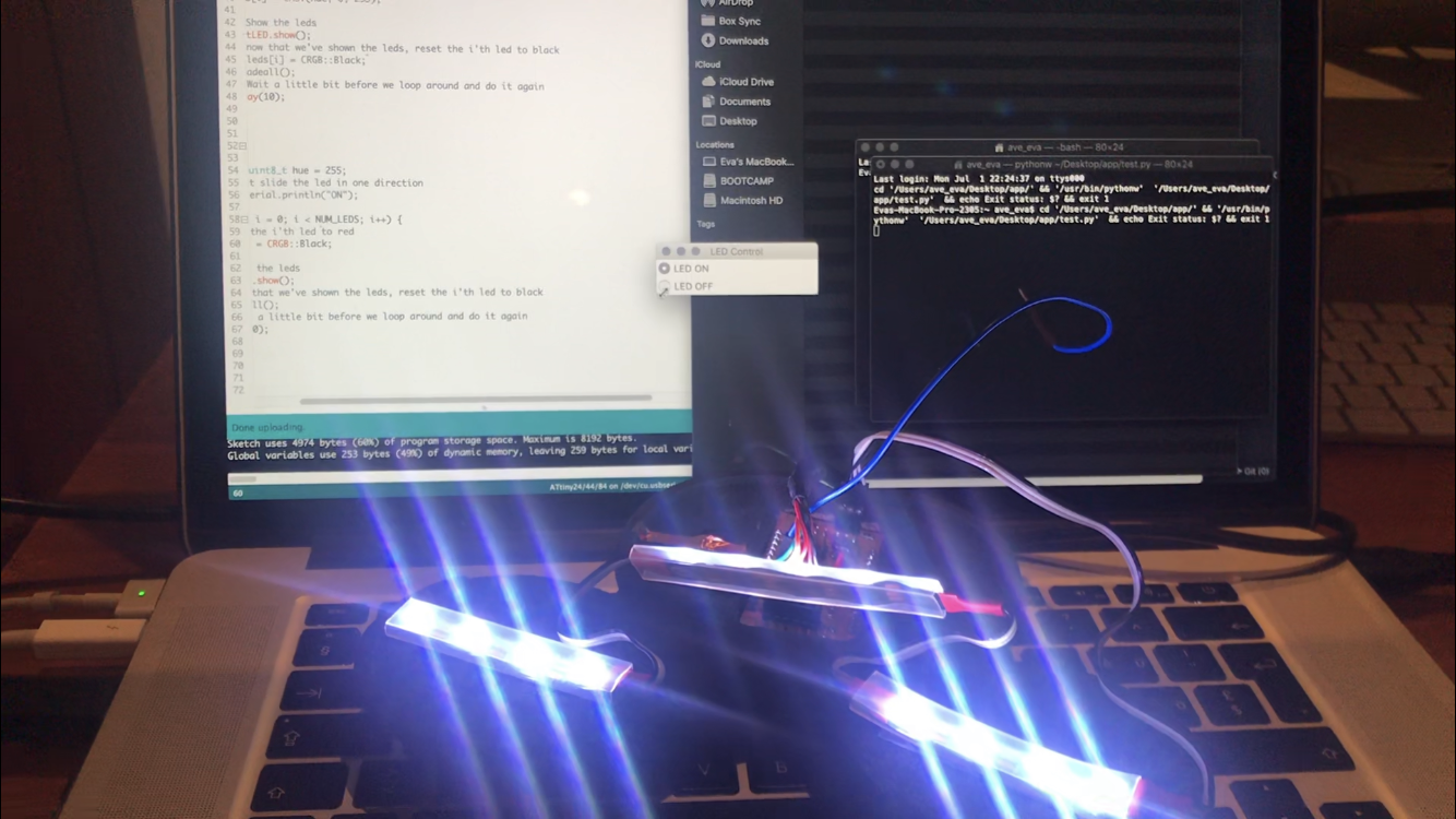
#image - light ON
#video demonstration - first with one LED. this was first test. (The other LED is signal that the board is powered).
#3 The aim is to create an augmented reality option to display the virtual object of the lamp within the existing environment. For an interface application, I wanted to make an app with unity/vuforia using image target as a tracking option. The idea was to create a possibility for an end user to place the lamp in the wished position within the interior and to check if it fits the composition of an existing situation.
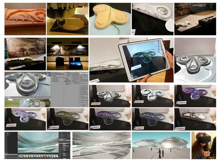
(Image from my thesis as na proof) And since I already had some experience with creating a similar strategy back in 2016 while working on my master thesis (see image) I wanted to follow up the same strategy. Unfortunately I was facing SW issues, had to reinstall unity again and the new unity was not able to open my old file. Now there is an upgrade - unity hub, thanx to this you can install any older version.
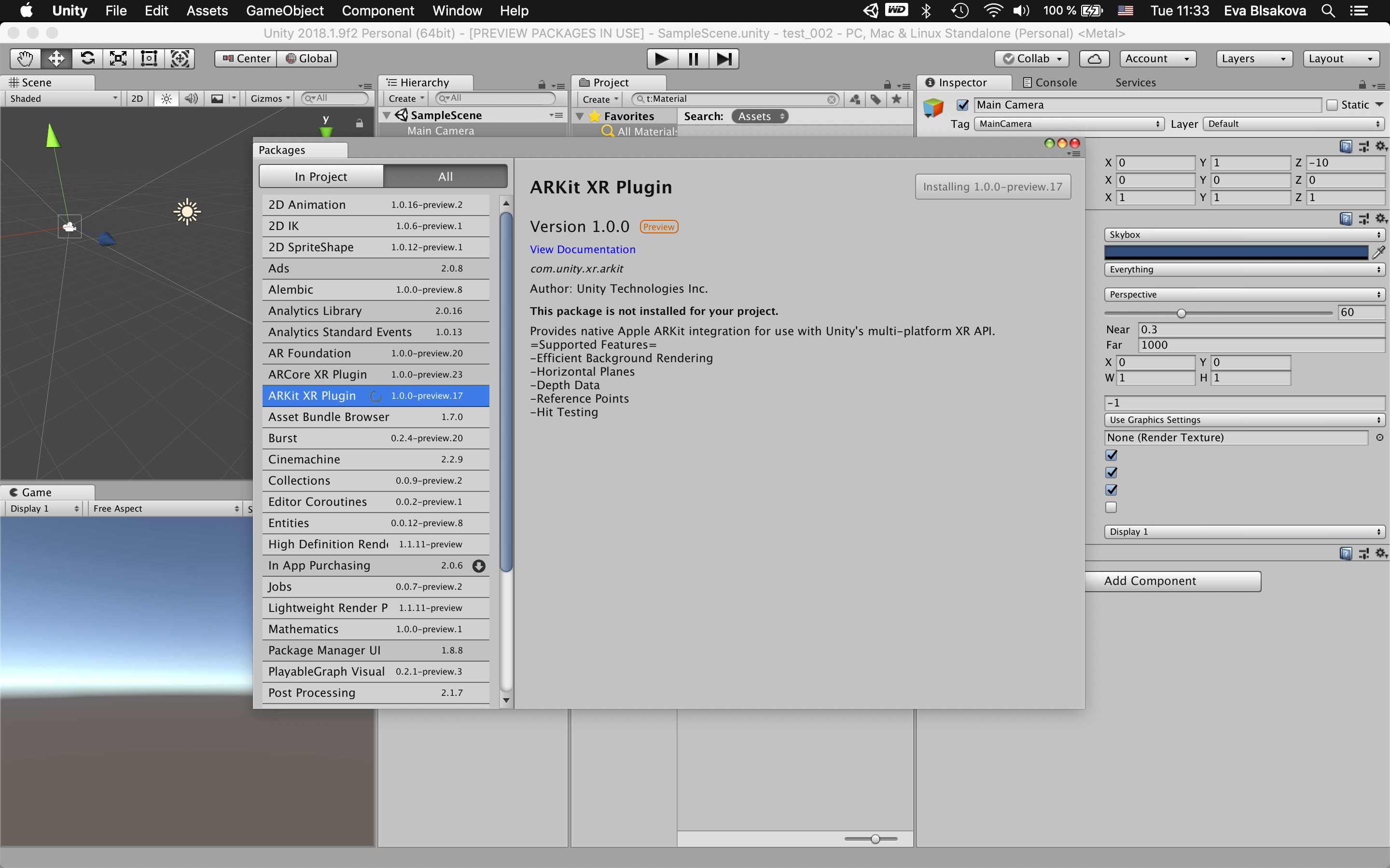
And since I didnt open unity for some time I needed to refresh my skills. I decided to revisit some tutorials for getting back to the process so I tried to follow this links: this link this link this linkIt was needed to install all necessary plugins too.
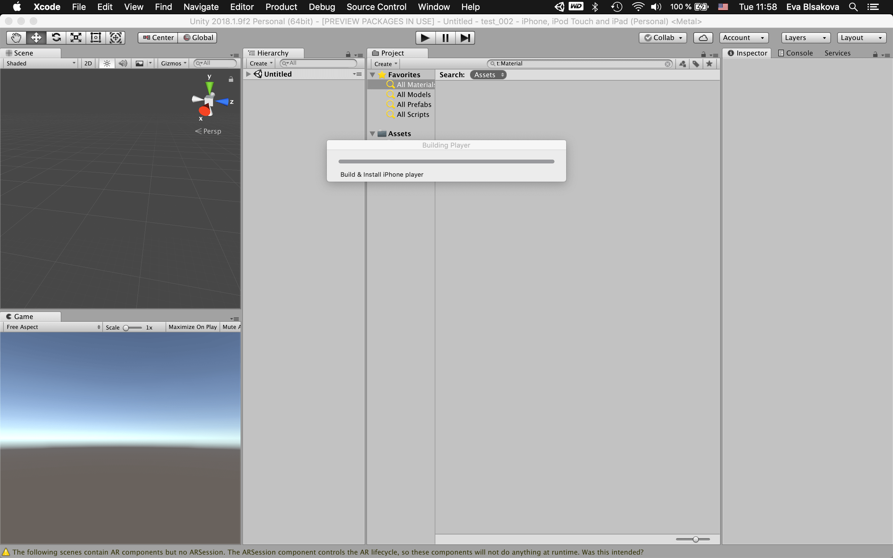
Than I placed simple 3D object - cube to the environment as a test, saved to the assets folder. It started to build and install iPhone player.
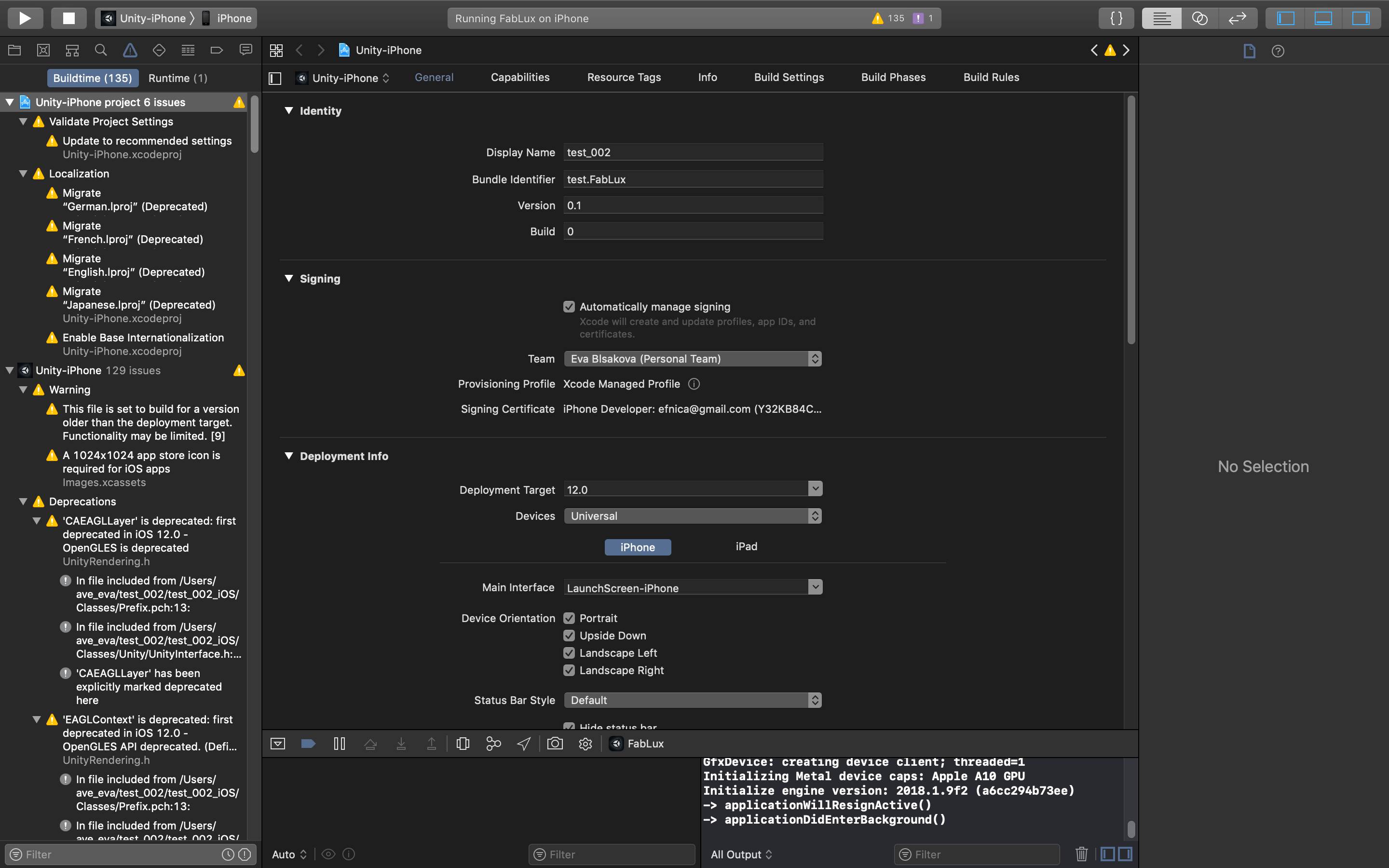
This process created in the same folder an xCode file, open it and follow filling out necessary fields. Dont forget to sign and put yourself as a team. otherwise it would scream an error. Modify the deployement info for wished target device, in my case it was iPhone with the latest iOS update. Connect iPhone with the cable, Run to Play and it creates the app in your phone. OK. this wuick test worked.
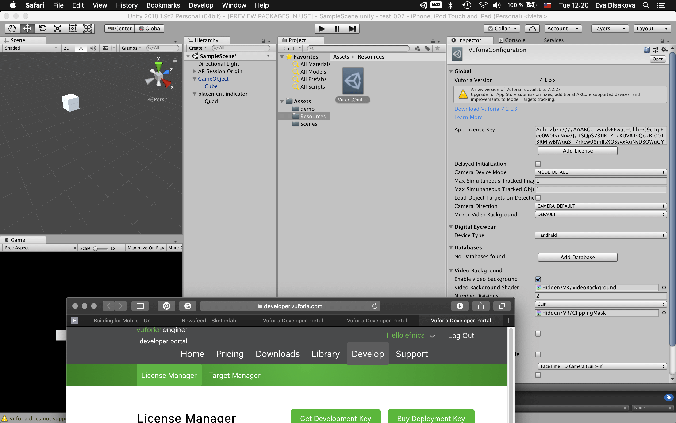
Than I wanted to jump on creation of image tracking AR with unity. on the vuforia developer portal https://developer.vuforia.com you upload the image with what you would like to track the app. Upload it, get the licence...
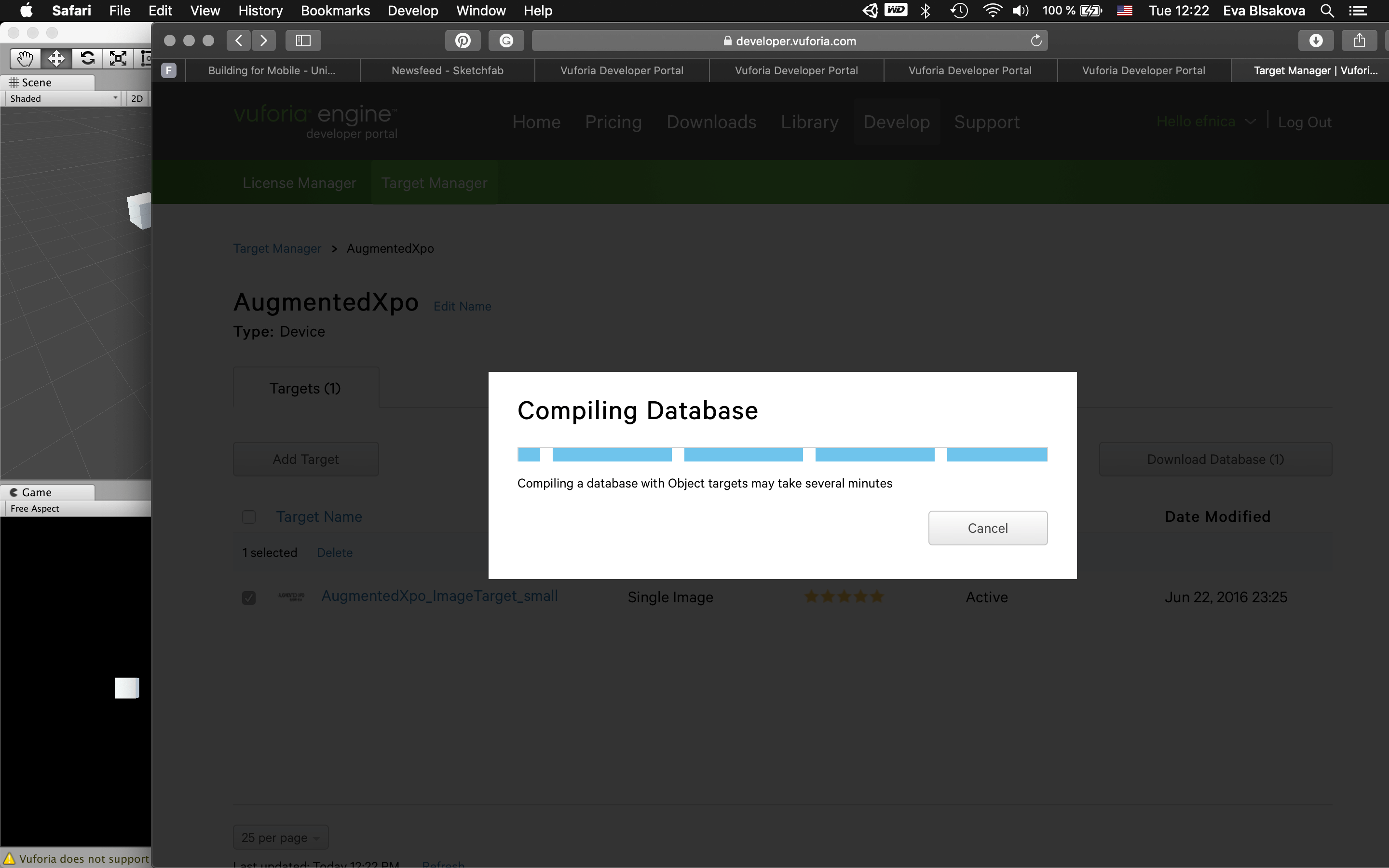
Compiling the database...takes a while...
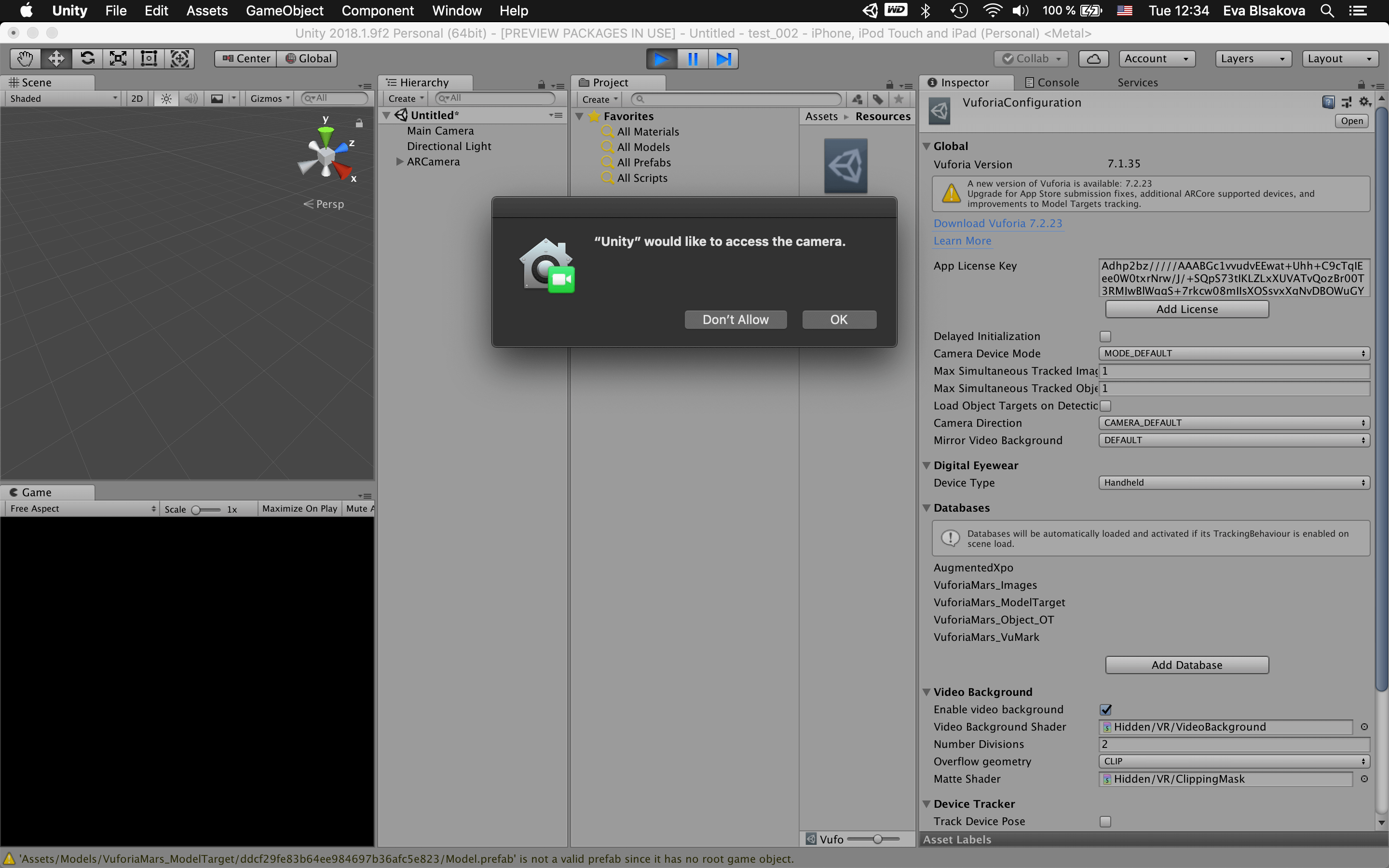
Allow Unity to use the front camera for testing.
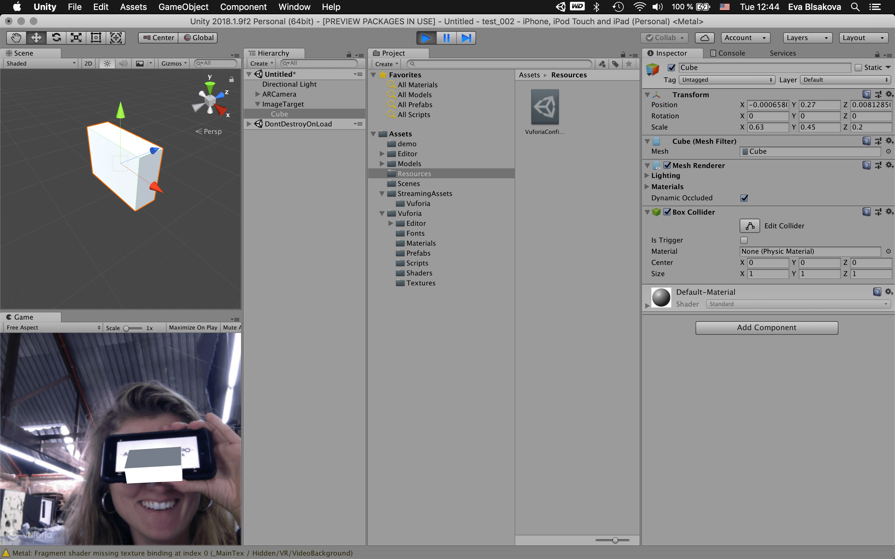
Now just place the target image in the field of view of the camera and wait till the object appears! So this was proove that my app was working. For saving the forest I decided to not print it out, just used my phone screen to display tracking image in order for achieving augmentation on it. success. Now I wanna replace the geometry with my own object.
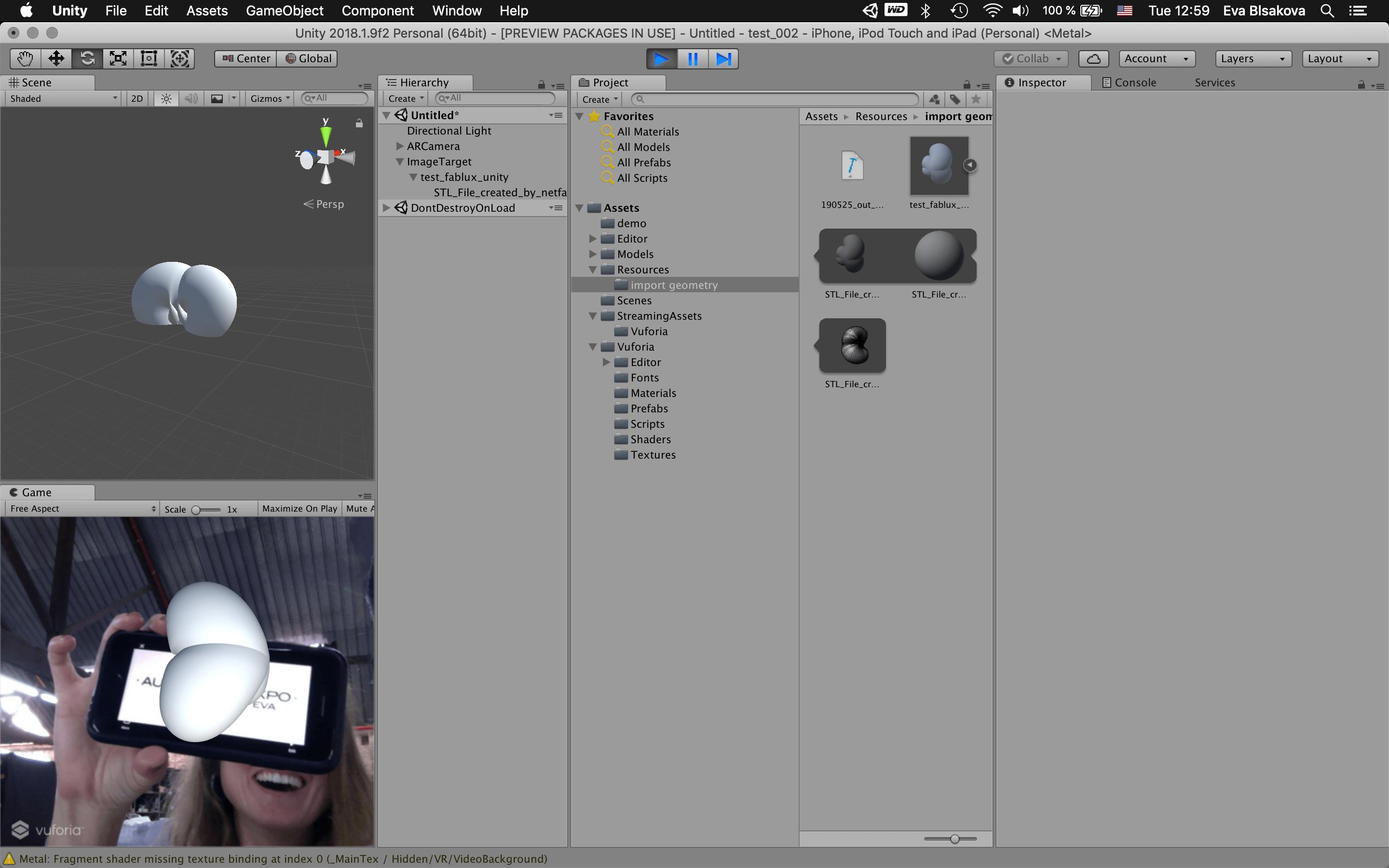
Replaced for my geometry lamp shell. WORKED! YES!
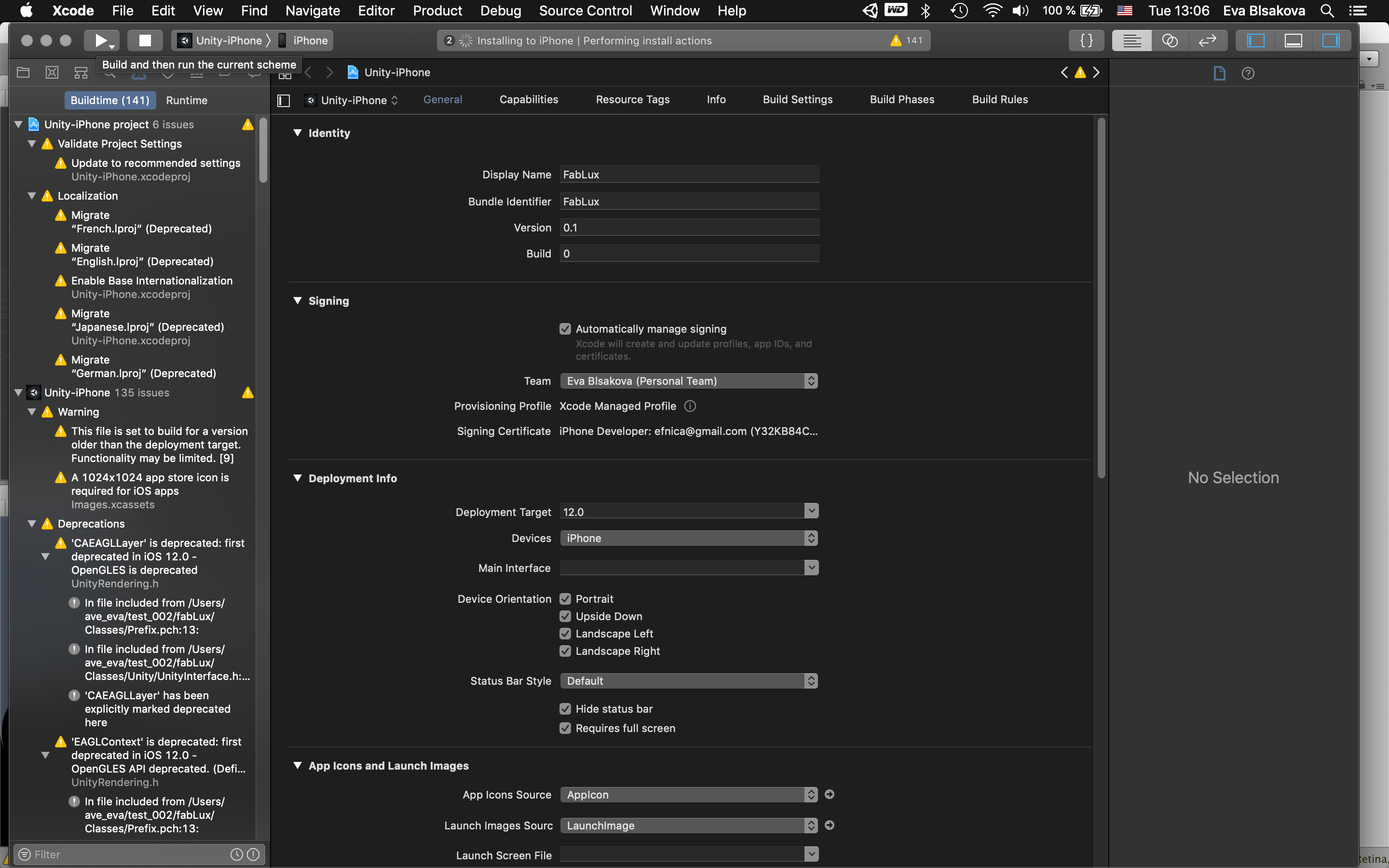
Build and Run to push it to xCode to make it in your phone...the same process as previously.
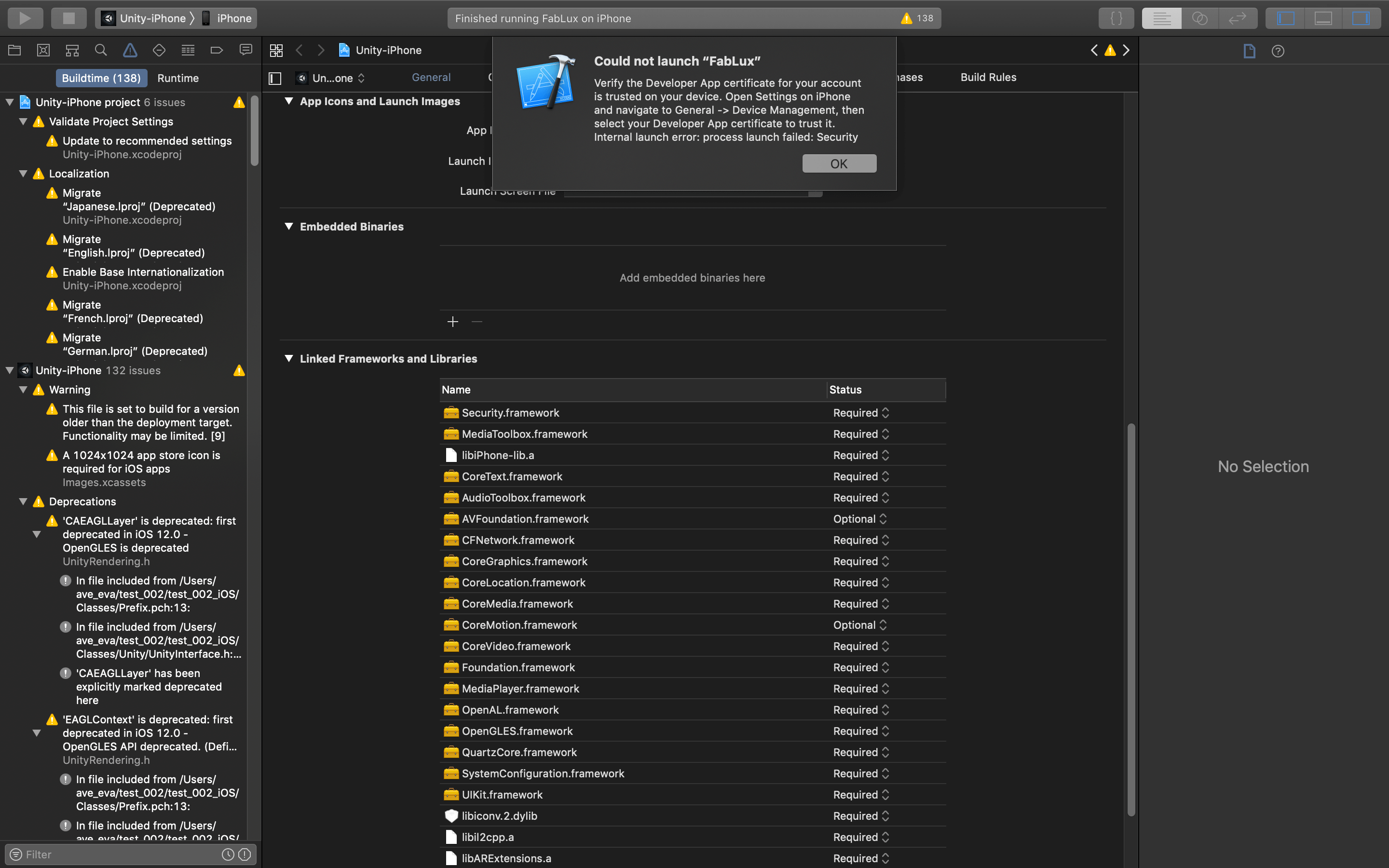
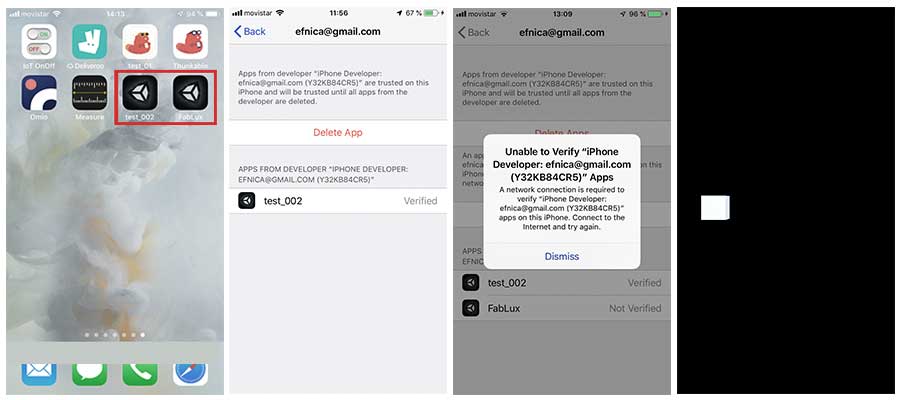
Of course you need to verify the app in your phone. So go to the Settings/General/Device Management and allow the developer app verification.