Output Devices
Group Assignment
This week's task was to:
Individual Assignment
So for this week assignment I had to connect an output device to my latest microcontroller board and program it to do something.
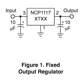
For my final project I have chosen already different sensors and a vacuum waterpump. The data transmitted by the output devices, should be sent by a bluetooth device to the mobile telefone. Here I had to use, same as here, a Voltage Regulater to convert the 5V, outgoing from the FabKitDA, to 3.3V, which is needed to run the Bluetooth device.
Then I also had to regulate the power supply of the vacuum water pump, which had to be regulated from 12V to 5V. For these circuits please see the assignmant of Week 18 - Project Development.
Components of the Circuit
Bluetooth Module - SH-HC-08 CC2541 Bluetooth 4.0

For more Information (click here).
FabKitDA and FabISP

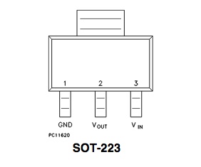
Voltage Regulator
Even though the LEDs were blinking correctly, this circuit wasn't good: The power supply with 5V voltage was to high and should have been 3,3V. The mistake was not to consider that the FabKit only supplies 5V.
Mobile Telefone
To get the mobile connected via Bluetooth I downloaded the application Light Blue to my Iphone.
Connecting and Programming Process
Before connecting the circuit, I had to program the FabkitDA PCB with my FabISP, as shown in this documentation:
Connecting my Iphone with the Bluetooth Module both boards were blinking.


Then I tried to connect the bluetooth board without using the FabISP. The RXD- and TXD-pins were connected to the pins MOSI and D10/SS, and the power supply would come from FTDI connection.
At least I could send my hello world in form of ola to my mobile telefone.


