Understanding electronics
What is a microcontroller?
A microcontroller is a small computer on a single integrated circuit.
Here are some (very brief) characteristics:
- Microcontrollers are dedicated to one task and run one specific program. The program is stored in ROM (read-only memory) and generally does not change.
- Microcontrollers are often low-power devices. A desktop computer is almost always plugged into a wall socket and might consume 50 watts of electricity. A battery-operated microcontroller might consume 50 milliwatts.
- Microcontrolles have inputs and outputs to communicate with the systems they control and other microcontrollers.
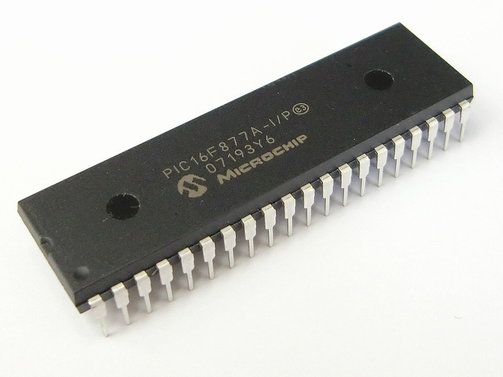
What are the pins in a microcontroller?
The microcontroller needs of means to be able to receive power, ground, input signals, and send outputs to the outter world. This are generally in the shape of pins. Sometimes, the pins are accessible for manual soldering, but it’s not always the case:

There are many different types of pins, some of the more common ones are listed below:
- Voltage / GND
- Digital Input/Output
- Special peripherals, such as ADC
- Timer
- Interrupts, RESET
Normally, these pins are grouped in PORTS. In 8-bit architectures, these ports normally comprise a total of 8-pins, and are saved in 8-bit registers. Internally, we can read these registers of these ports, or even change their function.
Arduino
The arduino framework and community provide an useful abstraction to this by providing a great amount of libraries that manage the internals of the microcontroller in a more user-friendly way.
Analog/Digital pin
A digital pin is able to detect whether there is a voltage present on a pin or not. An analog pin is connected to an internal ADC (Analog to Digital Converter) and can measure the actual voltage on the pin.
A digital pin is suited to detect if a button has been pressed, while an analog pin might for example measure the position of a potentiometer.

Input/Output
Input pins are used to read the logic state on some device. Pin can read if it is logic state “1” or “0”.
Output pins are used to send logic states to some devices. They can be set as push-pull or open collector. Push-Pull pin means that it can source and sink relatively big electrical current to connected hardware (turning ON or OFF one LED). In the case of open collector, it means that they can sink current only, but they cannot source it. Generally, all output pins are push-pull in common microcontrollers.
When reading inputs, it’s useful to use pull-up/down resistors, in order to avoid shorts, stabilise measurements and avoid faulty readings. The larger the resistance for the pull-up, the slower the pin is to respond to voltage changes.
A pull up resistor is used to bring the pin to the “1” digital level when there is no input:

Image Credit: Sparkfun
A pull-down resistor is used to force the pin to the “0” digital level when there is no input.
Learn more
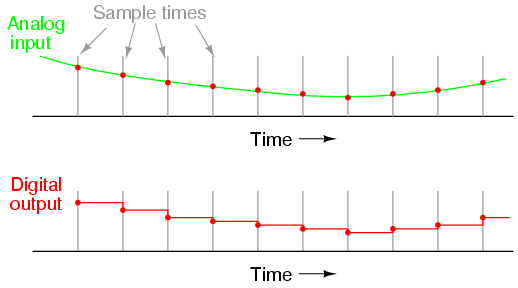
ADC
ADC stands for Analog to Digital Converter. It’s a system that converts an analog singal into a digital one. The resolution of the converter indicates the number of discrete values it can produce over the range of analog values.
GPIO
A general-purpose input/output (GPIO) is an uncommitted digital signal pin on an integrated circuit or electronic circuit board whose behavior—including whether it acts as input or output—is controllable by the user at run time. The ATtiny44, 84 has only one pin as a GPIO.
GPIO in a Raspberry Pi
A Raspberry Picontains a great deal of GPIOs that can be used for many things: I2C, Serial, SPI or PWM. Find out more here
How to talk to a microcontroller
Let’s see some basics before going into the specific protocols.
Serial vs. Parallel
Parallel interfaces transfer multiple bits at the same time. They usually require buses of data - transmitting across eight, sixteen, or more wires.
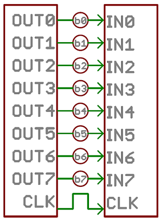
Image source: Sparkfun
Serial interfaces stream their data with a reference signal, one single bit at a time. These interfaces can operate on as little as one wire, usually never more than four:
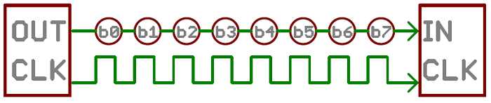
Image source: Sparkfun
More info
Check the Serial Communication Tutorial to understand why we use Serial communication in the ISP
Synchronous vs. Asynchronous
“Asynchronous” (not synchronous) means that data is transferred without support from an external clock signal. This transmission method is perfect for minimizing the required wires and I/O pins, but it does mean we need to put some extra effort into reliably transferring and receiving data.

Image source: Sparkfun
“Synchronous” data interface always pairs its data line(s) with a clock signal, so all devices on a synchronous bus share a common clock. This makes for a more straightforward, often faster transfer, but it also requires at least one extra wire between communicating devices.

Image source: Sparkfun
Serial communication
Some standards
FTDI
Future Technology Devices International, commonly known by its acronym FTDI, is a Scottish privately held semiconductor device company, specializing in Universal Serial Bus (USB) technology.[1]
It develops, manufactures, and supports devices and their related software drivers for converting RS-232 or TTL serial transmissions to USB signals, in order to allow support for legacy devices with modern computers.[2]
FTDI provides application-specific integrated circuit (ASIC) design services. They also provide consultancy services for product design, specifically in the realm of electronic devices.

The pinout:

FTDI Needs drivers!
Download them here
Fabacademy it yourself
SPI
Serial Peripheral Interface (SPI) is a synchronous serial protocol, used for short-distance communication, primarily in embedded systems.

Image Credit: SparkFun
It uses a master-slave architecture with a single master. The master device originates the frame for reading and writing. Multiple slave-devices are supported through selection with individual slave select (SS) lines.
SPI is used by most programmers to flash the microcontroller’s code onto the flash memory.
Want to know more?
Check the SPI section on the networking page, to learn more!
USB
The universal serial bus or USB is an standard communication protocol used to unify the connection of peripherals like keyboards, video cameras, printers, attached to personal computers, both to communicate and to supply electric power. USB cables are limited in length, as the standard was meant to connect to peripherals on the same table-top, not between rooms or between buildings.
USB uses differential signalling to transfer information, using two signals. The technique sends the same electrical signal as a differential pair of signals, each in its own conductor. The pair of conductors can be wires (typically twisted together) or traces on a circuit board.
| Pin Number | Cable Colour | Function |
|---|---|---|
| 1 | Red | VBUS (5 volts) |
| 2 | White | D- |
| 3 | Green | D+ |
| 4 | Black | Ground |
Digested specification
Find it here
Examples
An example of all this in a fabacademy board:
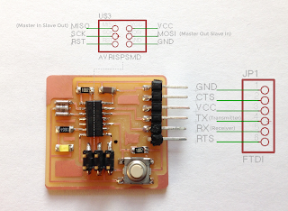
And more globally:

The memories in a microcontroller
Let’s start from the very basics and understand how a microcontroller manages it’s memory. In general, there are three types of memory in a microcontroller:
- Data memory : memory for storing the data processed during run time (including also the registers, stack, etc.). This memory is a volatile memory, meaning, when the device is reset, it will be lost.
- Program memory: memory in which the program (or code) is stored. This memory is non volatile, meaning that it won’t be lost if the device is reset.
- EEPROM : memory which can be used for storing non volatile data and changeable during run-time.
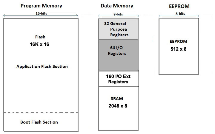
Image credit: Arduino
Depending on the type of microcontroller, each memory will have different sizes, or it might not even exist. Here, we will focus on the Program Memory, sometimes also called Flash Memory. Program Memory (also Read-Only-Memory) is used for permanently saving the program (CODE) being executed, and it can be divided into two sections: Boot Program section and the Application Program section.
The boot loader section
In the image above, one might have noticed that there is a dedicated part of the program memory to something called Boot Flash Section. This is also sometimes called bootloader or boot program section and it’s a part of the program that executes after every time there is a reset of the microcontroller. This area of the memory is protected against deletion and can not be rewritten unless one specifically means to do so. It also has the capability to change the major part (application section) of the flash content. The purpose of this bootloader area is to connect the microcontroller to the outer world, for example a PC, and transfer a new firmware into the main part of the flash memory. This is normally done at the very beginning of the microcontroller wake-up and, in case of: 1. failure in the transfer or 2. no PC requesting to send a firmware into the flash, the bootloader should finish it’s job and hand-over the control to the main part of the firmware, if any.
Now, what happens with the ATtiny44? Well, that it simply has no bootloader section in the flash memory (Page 159 of the ATTiny Datasheet), and more importantly, it’s not waiting for any external device to program it via Serial Protocol, such as USB. This means that we need other means to access the flash memory of the microcontroller and, for this, we will use an ISP programmer.
ISP (In-system-programming)
In-system programming (ISP), also called in-circuit serial programming (ICSP), is the ability of some programmable logic devices, microcontrollers, and other embedded devices to be programmed while installed in a complete system, rather than requiring the chip to be programmed prior to installing it into the system.
Here you can see the pinout of ISP:

And how to identify the connector:

Learn even more!
An ISP programmer is therefore a specialized hardware that will be used to reflash microcontrollers without this bootloader section, which we won’t be able to connect directly to a PC. Also, it can be used to reflash the bootloader into the microcontroller. Further reading can be found here regarding bootloaders and ISP, as well as the Arduino Reference for this topic.
More reference
Finally, to have further reference, much more detailed information can be found in this ATMEL/Microchip Application Note.
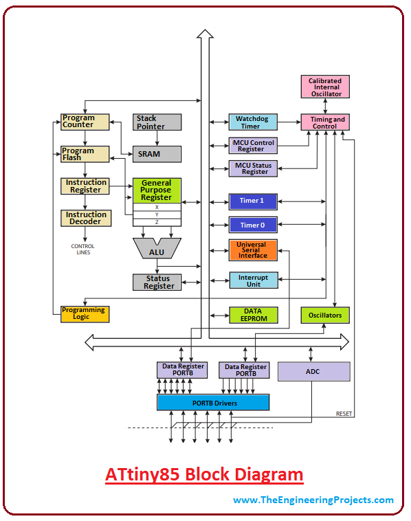
Our chip: the ATtiny
An introduction to the ATtiny in this Guided version.
Datasheet
Have a look at the Attiny 44 Datasheet
Pinout

Explore the core