Lasercutter
The laser cutter we were using is an Epilog Zing 6030 with a 30W laser. Together with the other students, we tested the kerf, speed and power of the laser cutter for a specific material. More information on that and how to operate this laser cutter can be found here. Now I know how to test the kerf for a new material and also how to test which speed and power I should set to get clean cuts in a new material.
Parametric triangles
As first I decided to create a parametric model. This I did in OpenSCAD again, as it is easy to use parameters there to change the model. I decided to create parts that could be connected into an hollow triangle and use a joint that is bigger at one end. With cutting 16 triangles I could connect them into each other and get a 3D structure, like this:

After trying to create the triangles in Inkscape I switched to paper to get the distances and angles I need to make the model in OpenSCAD. I started to create a rectangle, then moved two of the points inwards to get a 30 degree angle. Then I added two points on each of the lines with an 30 degree angle, evenly spaced on the lines. The spacing can be changed with the js and je parameters in the module. Then I added those two points again and moved them inwards on one side and outwards on the other side to get a joint. Those are moved inwards by the parameter intr, so if the joint should be longer or shorter this parameter can be adjusted. The parameter d and k adjust how much the joints are skewed.
length = 10;
height = length/16;
kerf = 0.015;

module triangle_side(l, h, kerf) {
    pl = h/tan(30); //peak length
    intr = sqrt(h*h+pl*pl)/7; //intrude length
    js = 1/3; //fracture after which the joint starts
    je = 2/3; //fracture after which the joint end
    d=0.05; //joint thickness along the edge
    k=0.1; //joint intrude
    polygon([   [0-kerf,0],
                [l+kerf, 0],
                [l-pl*js+k*sin(30), h*js+k*cos(30)+kerf],
                [l-pl*js-intr*sin(30)+d*cos(30)+k*sin(30), h*js-intr*cos(30)-d*sin(30)+k*cos(30)+kerf],
                [l-pl*je-intr*sin(30)-d*cos(30)+k*sin(30)+kerf, h*je-intr*cos(30)+d*sin(30)+k*cos(30)],
                [l-pl*je+k*sin(30)+kerf, h*je+k*cos(30)],
                [l-pl+kerf, h],
                [pl-kerf, h],
                [pl*je+k*sin(30), h*je-k*cos(30)+kerf],
                [pl*je-intr*sin(30)+d*cos(30)+k*sin(30), h*je+intr*cos(30)+d*sin(30)-k*cos(30)+kerf],
                [pl*js-intr*sin(30)-d*cos(30)+k*sin(30)-kerf, h*js+intr*cos(30)-d*sin(30)-k*cos(30)],
                [pl*js+k*sin(30)-kerf, h*js-k*cos(30)] ]);
}

triangle_side(length, height, kerf);
As you can see in the code the parameters are length of the triangle side and kerf. Before cutting all the parts I cut a few triangles with different values for kerf and found out that the best fitting triangles were the one which adjusted for 0.15mm kerf. You can assemble the triangle sides in multiple ways to form flat structures:
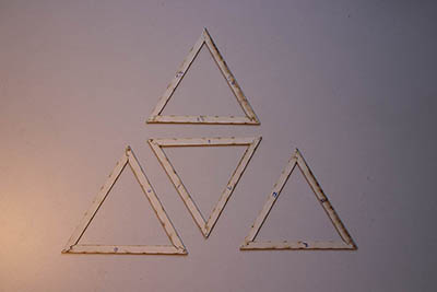
Small triangles
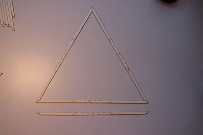
A big triangle
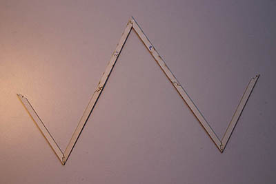
A letter
But you can also create 3D structures by nesting the triangles:
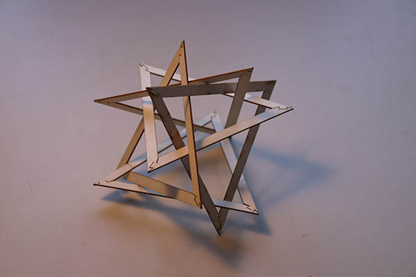
4 triangles
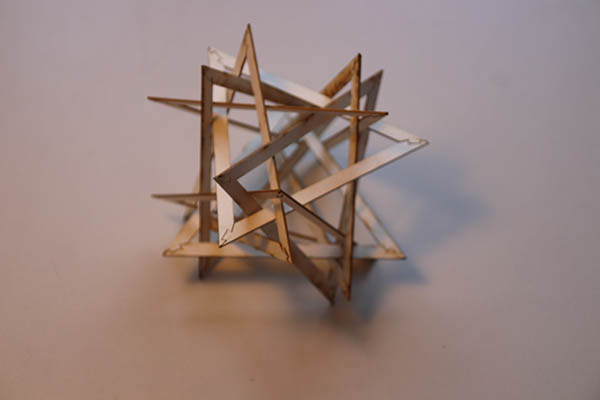
8 triangles
X-Wing
I wanted to create a press fit construction kit. I have heard of a program called flatfab in the previous weeks and wanted to do something with it, but never had the idea. Now that we tested the laser cutter this came to my mind again and I wanted to create something with it. To get ideas and also a template I went to free3d and found this awesome model of an x-wing. So I went to create an x-wing in flatfab:

The flatfab logo
At first, the flatfab interface and shortcuts are hard to understand, but after watching the tutorials on modeling it was easy to work with the program. First I exported the x-wing from blender into an obj format, so that I could use the model in flatfab as a template. Then I first created the horizontal main part where I connected everything else. I created some round parts to show the size of the cabin and there I also connected the wings. I added weapons, turbines and used the blend command to create the rest of the round parts for the cabin. At last, I added a stand. You can see the progress in the following gif:
The creation of the x-wing
I wanted to cut the model from 1.5mm MDF, to get a sturdy and at the same time fine model. As we calculated the kerf in the group assignment I first did a test on how much I should remove material, because for the best fit it might be desirable to remove more than just the double kerf (for each side of the joint). In flatfab, you could specify the material thickness for exporting. When checking the sizes in Inkscape I realized that flatfab already makes he joints a bit smaller (for the kerf).
I cut one part of the model for testing the adjustment to make for the kerf. Therefore I cut the same part four times: First without adjusting for the kerf. Then making the material smaller by the size of the kerf times 1, 2 and 3. I expected the best results for 2.
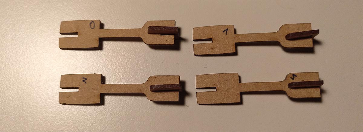
The test cuts to adjust for the kerf
But surprisingly the best results were achieved for removing the kerf three times from the material thickness. Zero and one would be loose, and also two times would not be very fixed. But when trying to assemble the whole model I realized that I tested the loosest joint of the whole model. All the other parts needed a lot of force to put together and it was very hard to put the model altogether. The lesson I learned from that is test for kerf adjustment with multiple connections and not just one.
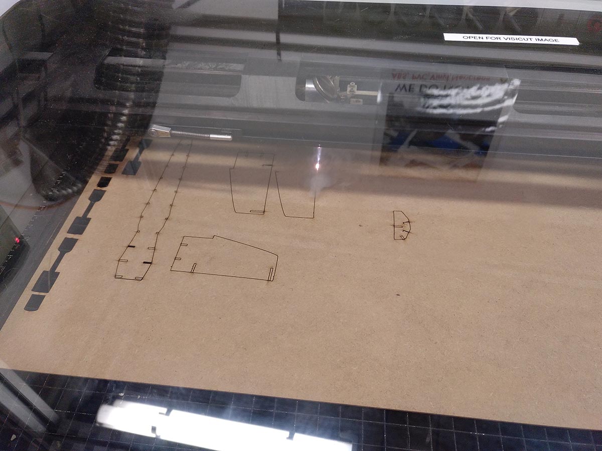
Cutting the MDF
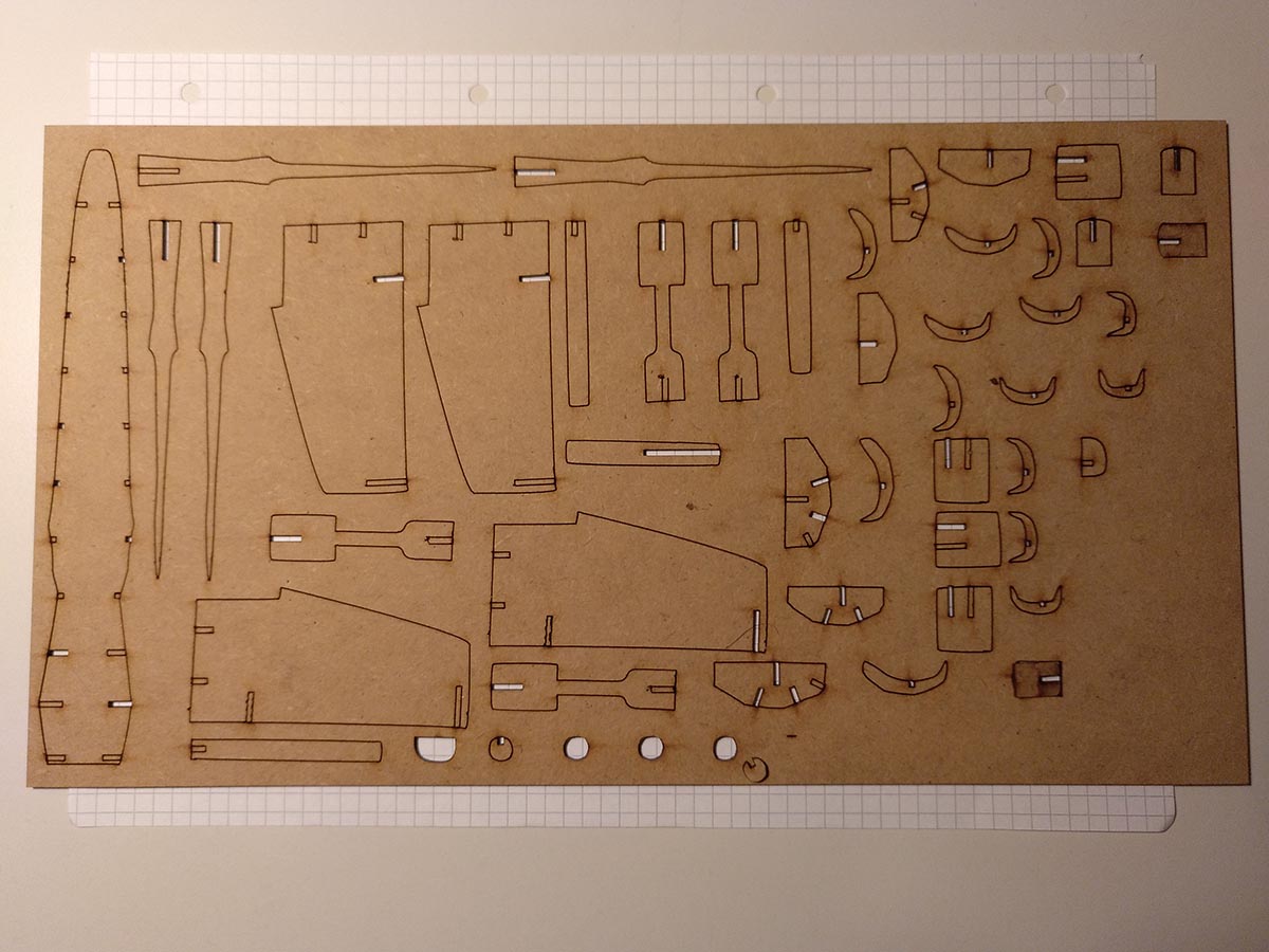
The finished cut
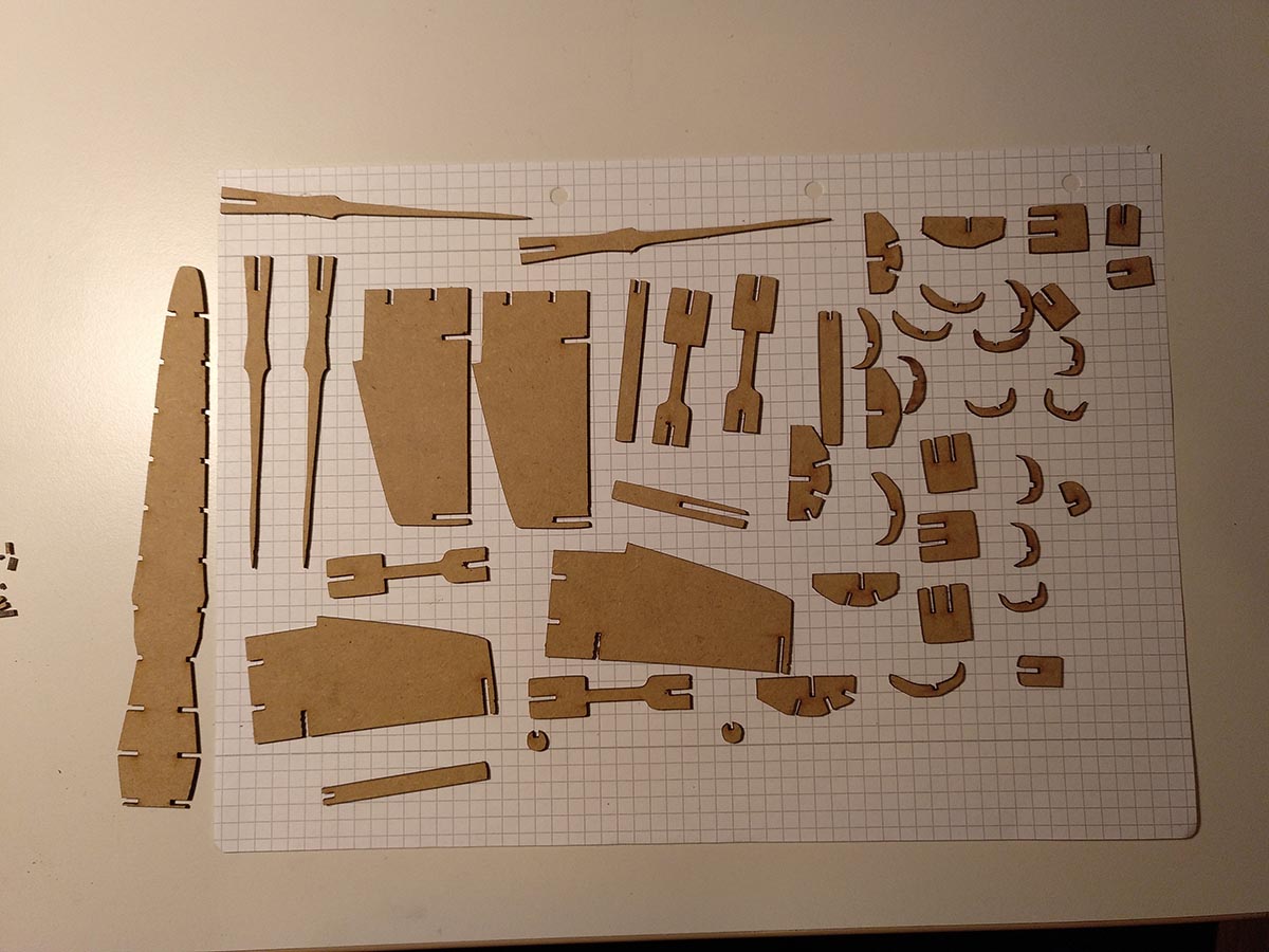
Seperated all the parts
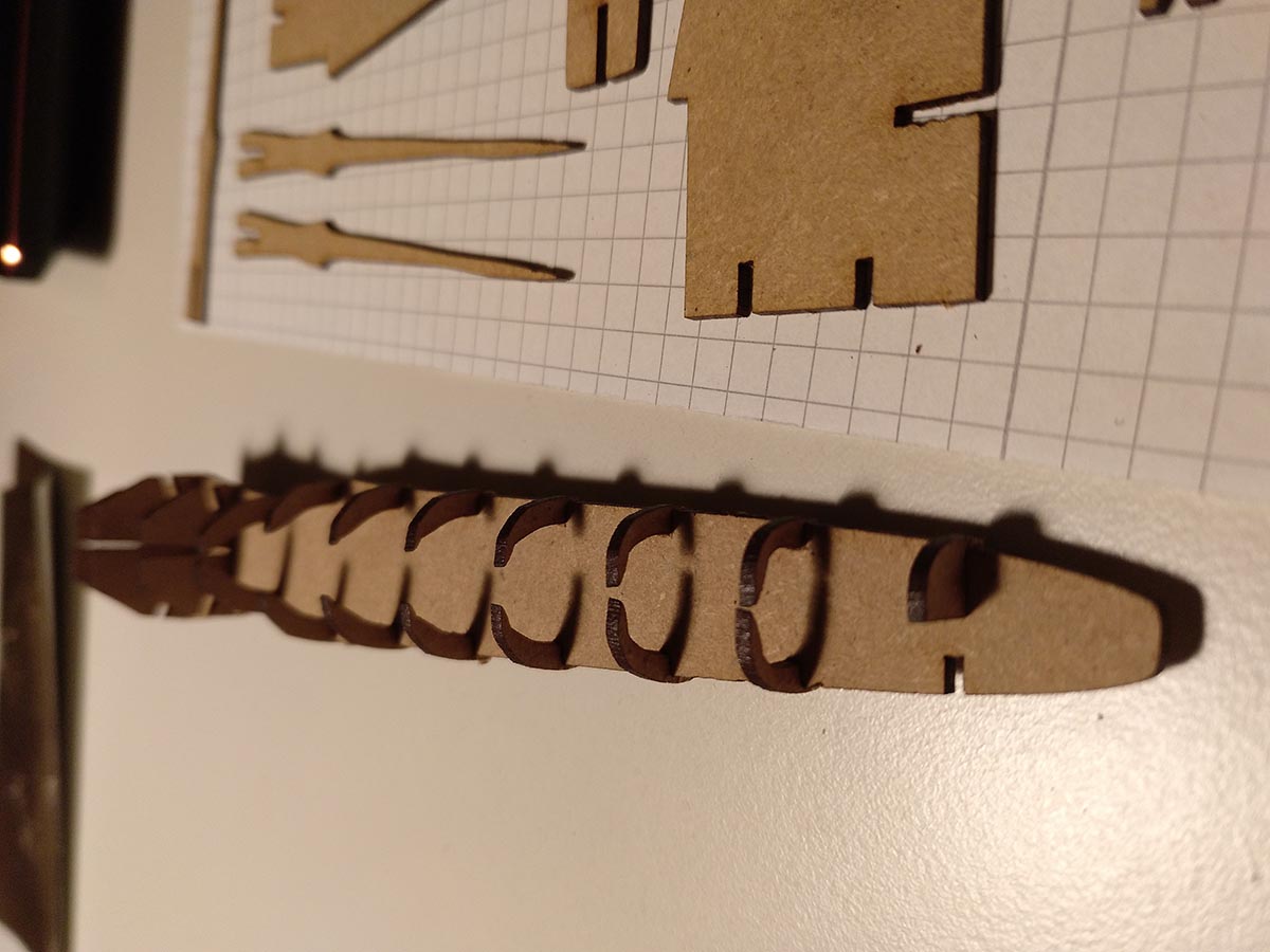
Starting the assembly
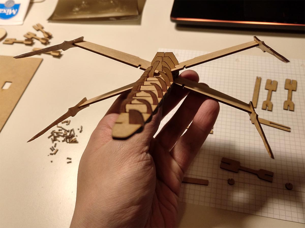
Nearly finished
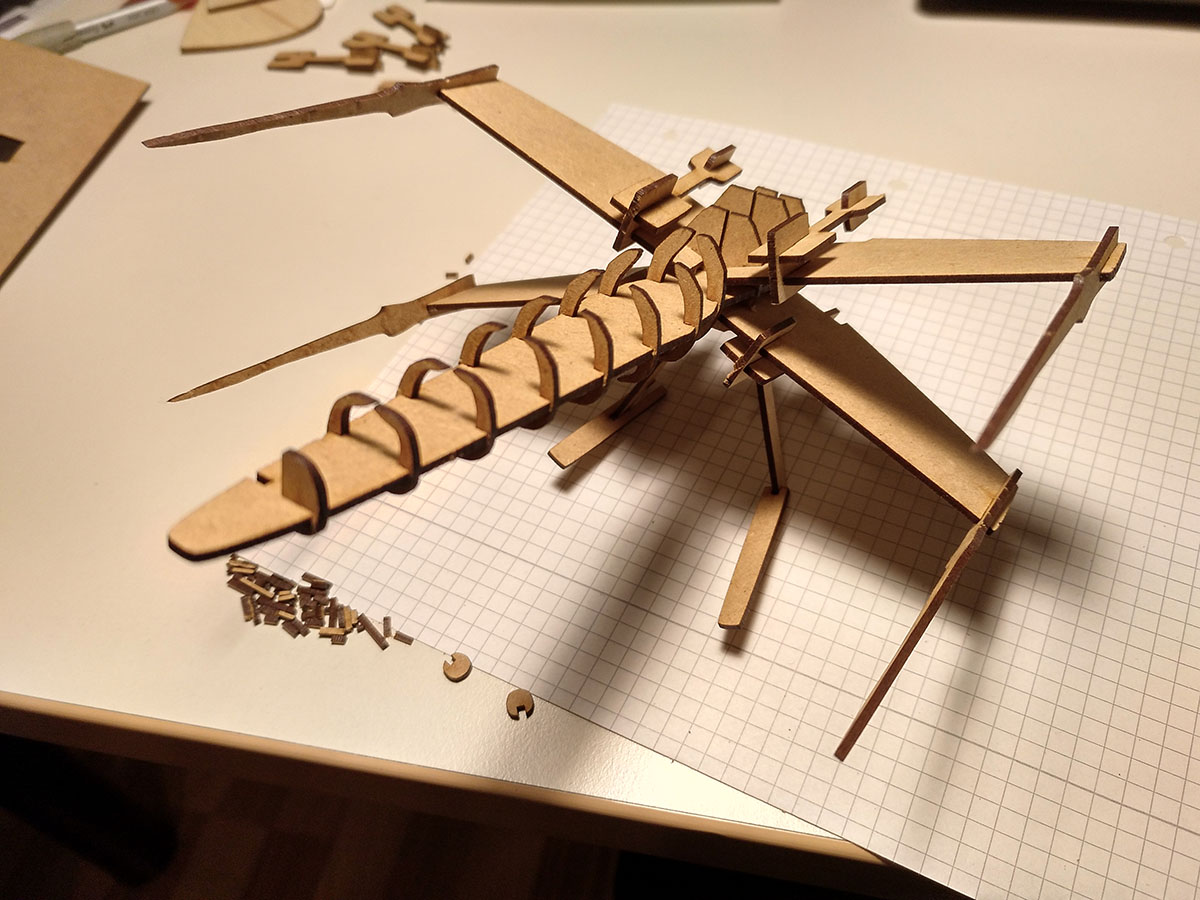
The finished model
Deer
Finally, I wanted to create something artistic using the laser cutter and got inspired by a wall art deer. To recreate this I traced the deer in Inkscape by hand. Therefore I followed a tutorial on youtube. This resulted in the following svg file:

The traced deer
I wanted to use a different material on the deer and decided to go with acrylic because you can get some nice effects with light shining through it.
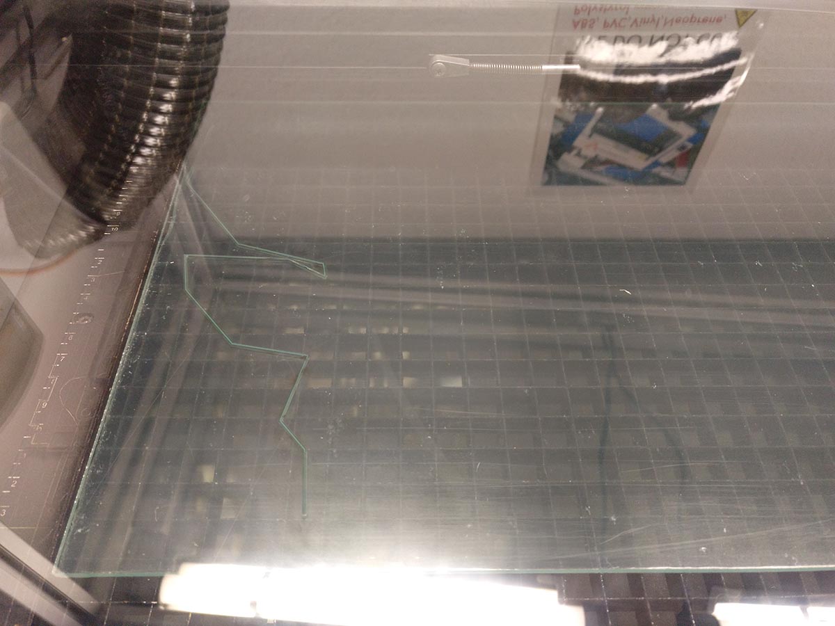
Cutting the acrylic
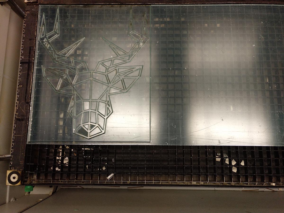
The finished cut
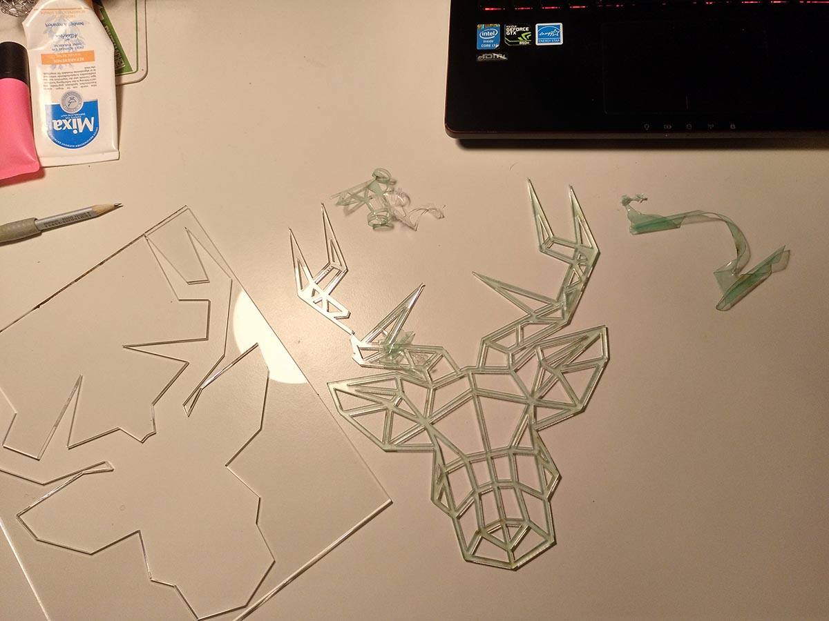
Separating all the parts
Unfortunately, the acrylic was not separated in all parts of the cut, at some places it was glued together again. When trying to remove it I accidentally broke the model, so then I took a cutter to separate the other glued positions. I also used glue to fix the model afterward.
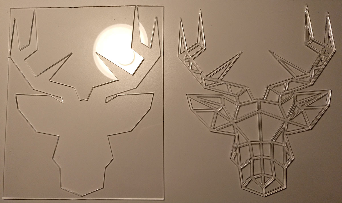
The finished cut
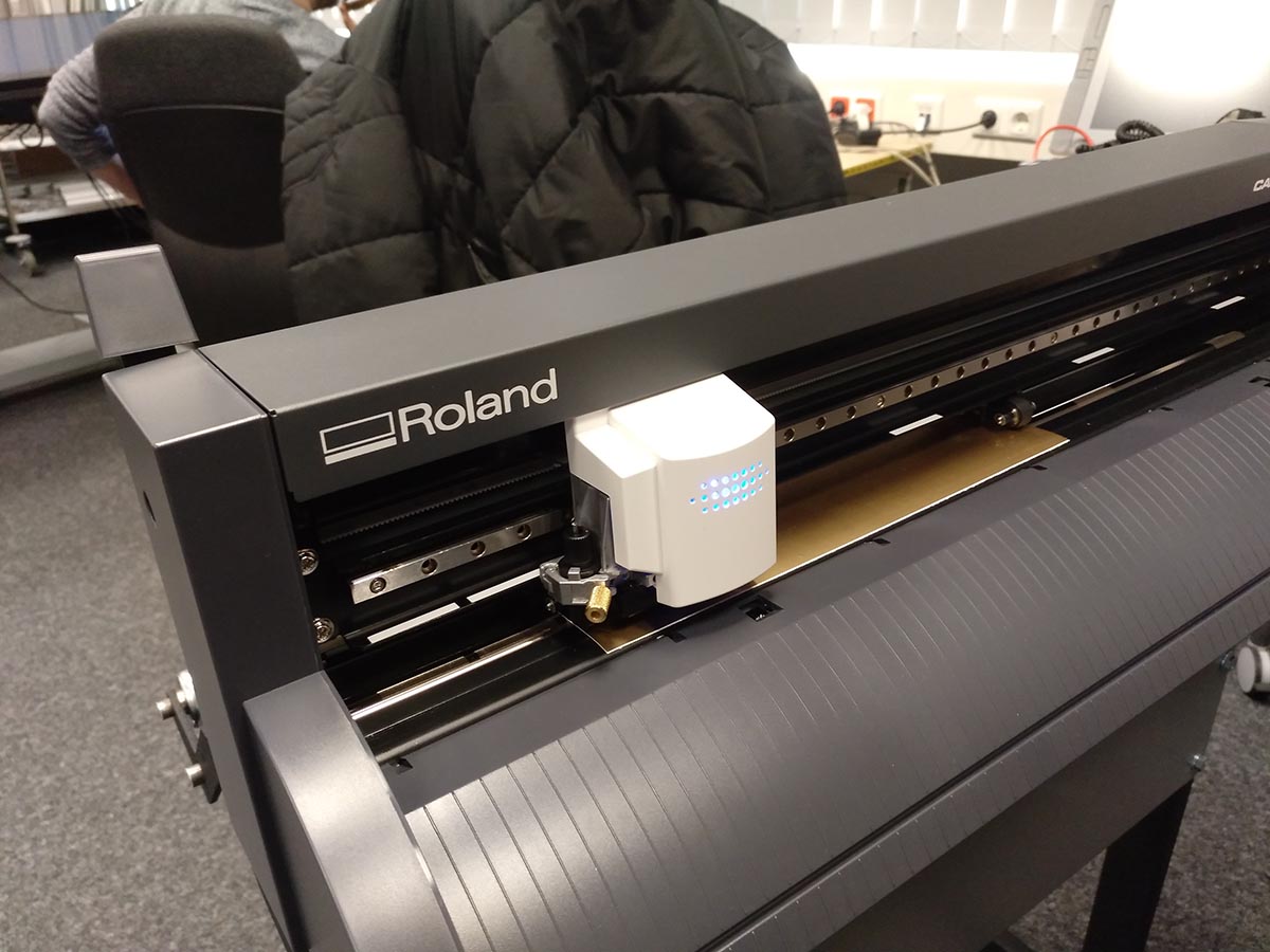
Vinyl cutter
We were using the Roland CAMM-1 GS-24 in this section. This is a super fast and precise cutter but it was a pain to get everything set up so we could use the cutter. I was not able to use the cutter under windows. The way we got to work with the cutter was using inkcut, an extension for inkscape under Linux. I currently do not have Linux installed, so I used the laptop of another participant of the fab lab. He also described the process of setting up the cutter under Linux detailed on his site.
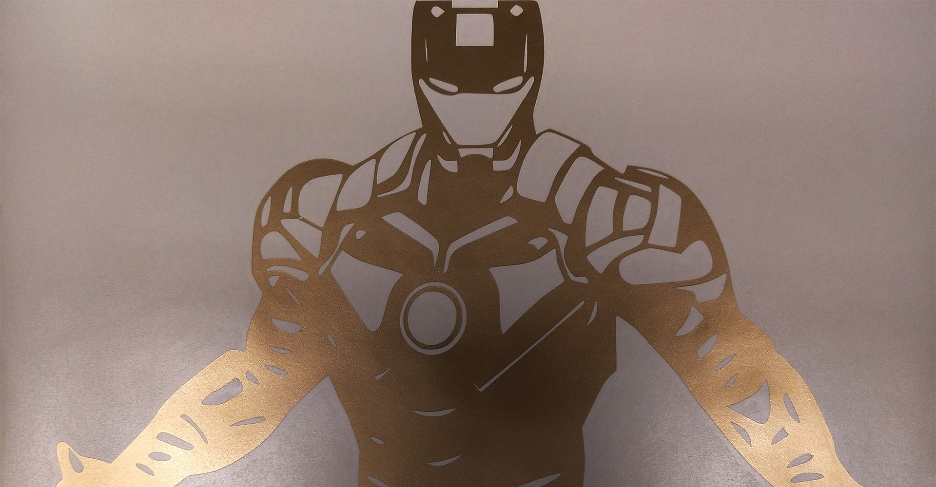
I wanted to create a sticker for my laptop and one for my smartphone and found some inspiration for an iron man sticker and a sticker with Calvin and Hobbes. I traced the image with Inkscape to get an svg file for the vinyl cutter.
To use the vinyl cutter we loaded the piece of foil and started the cutting job:
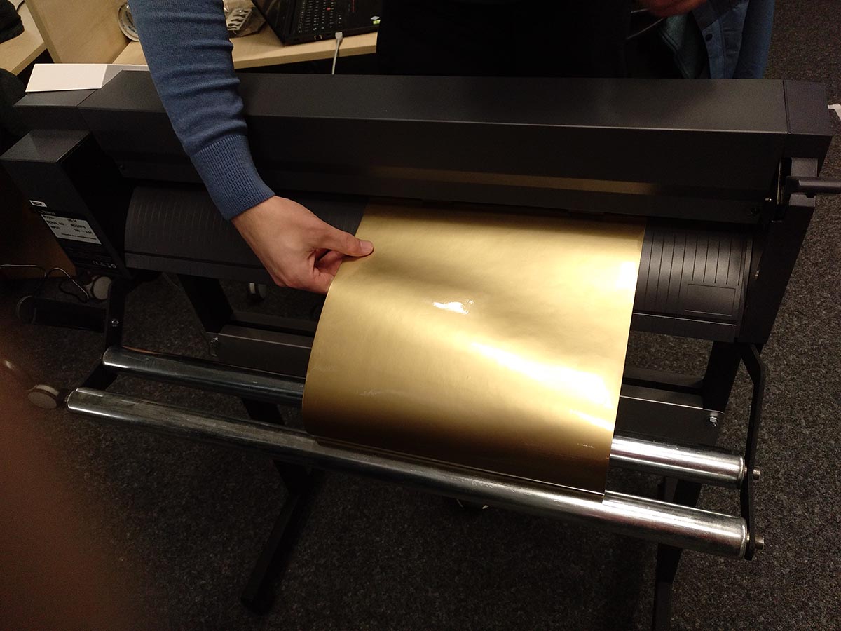
Insert the foil
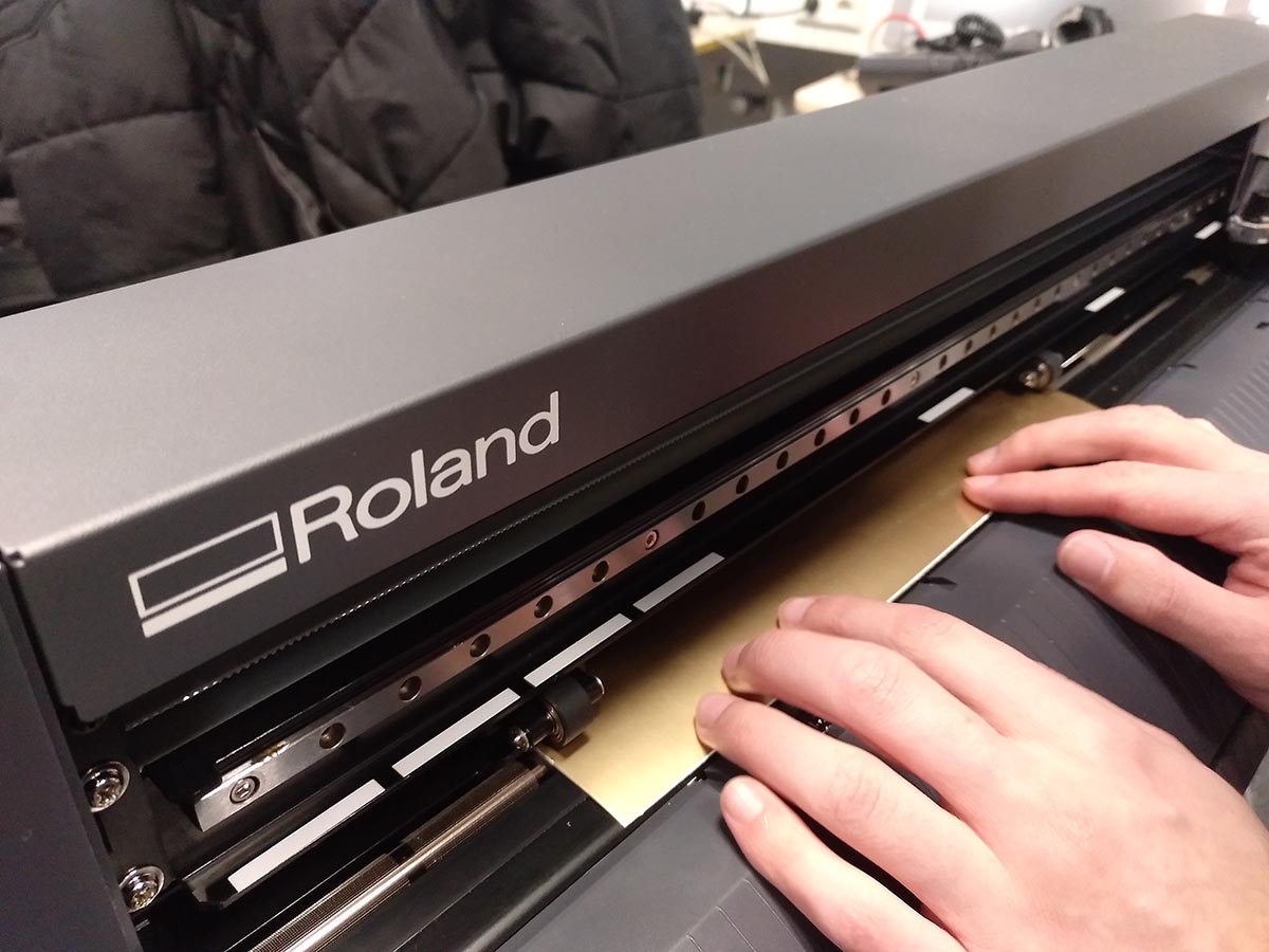
Align it to two of the white markers
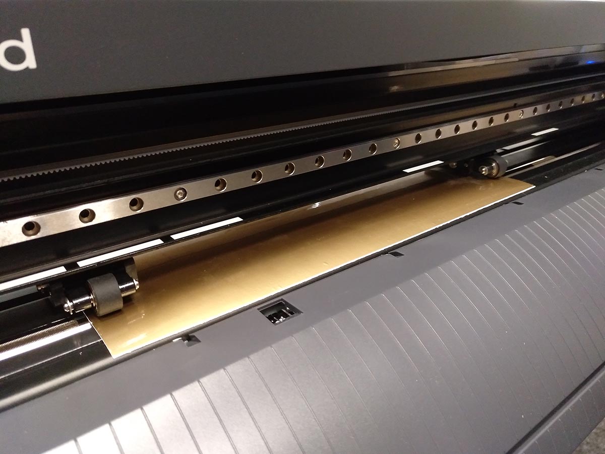
Align the two rollers
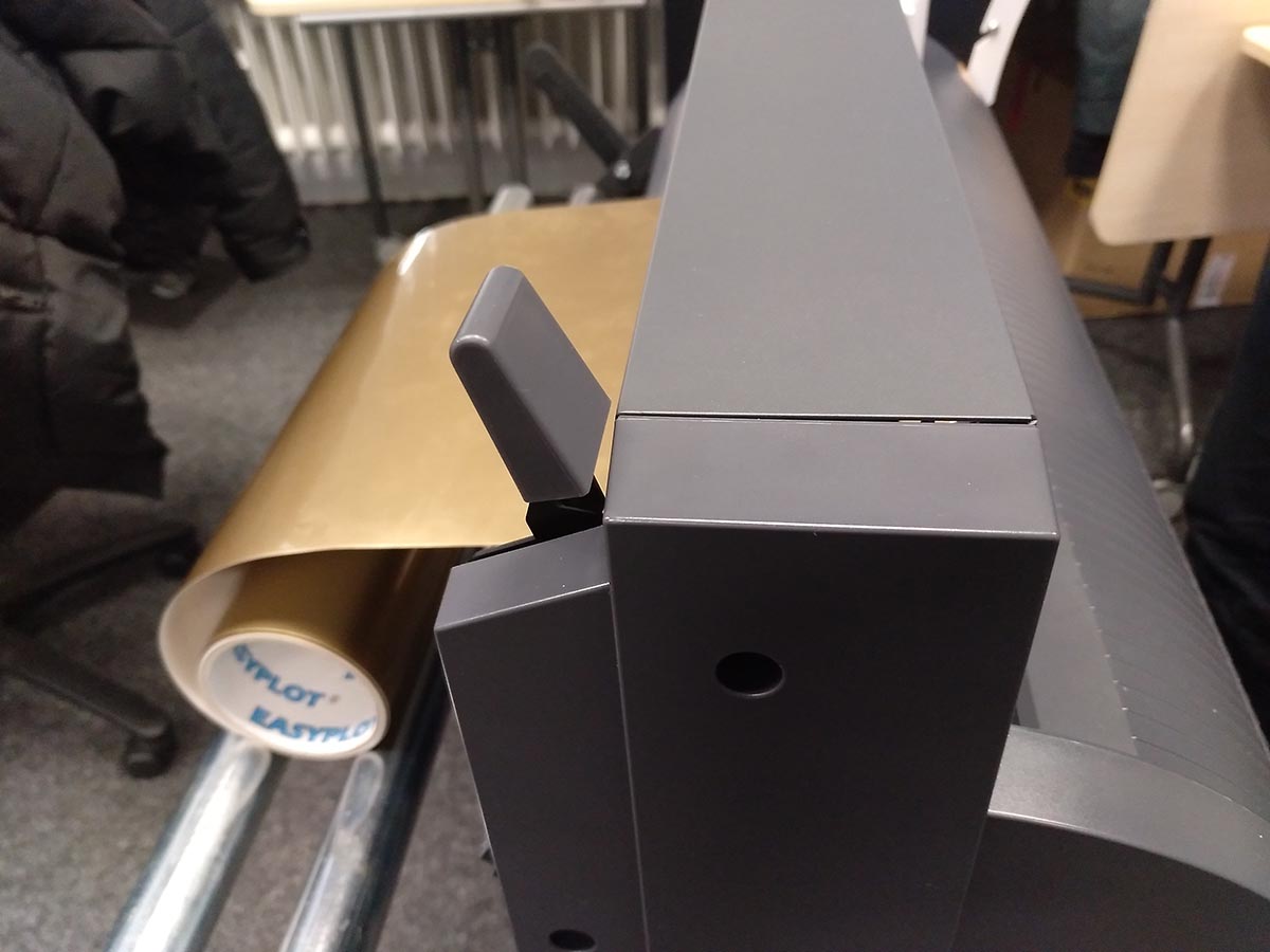
Flip the lever to hold the foil in position
After pressing Enter the cutting head measures the size of the piece
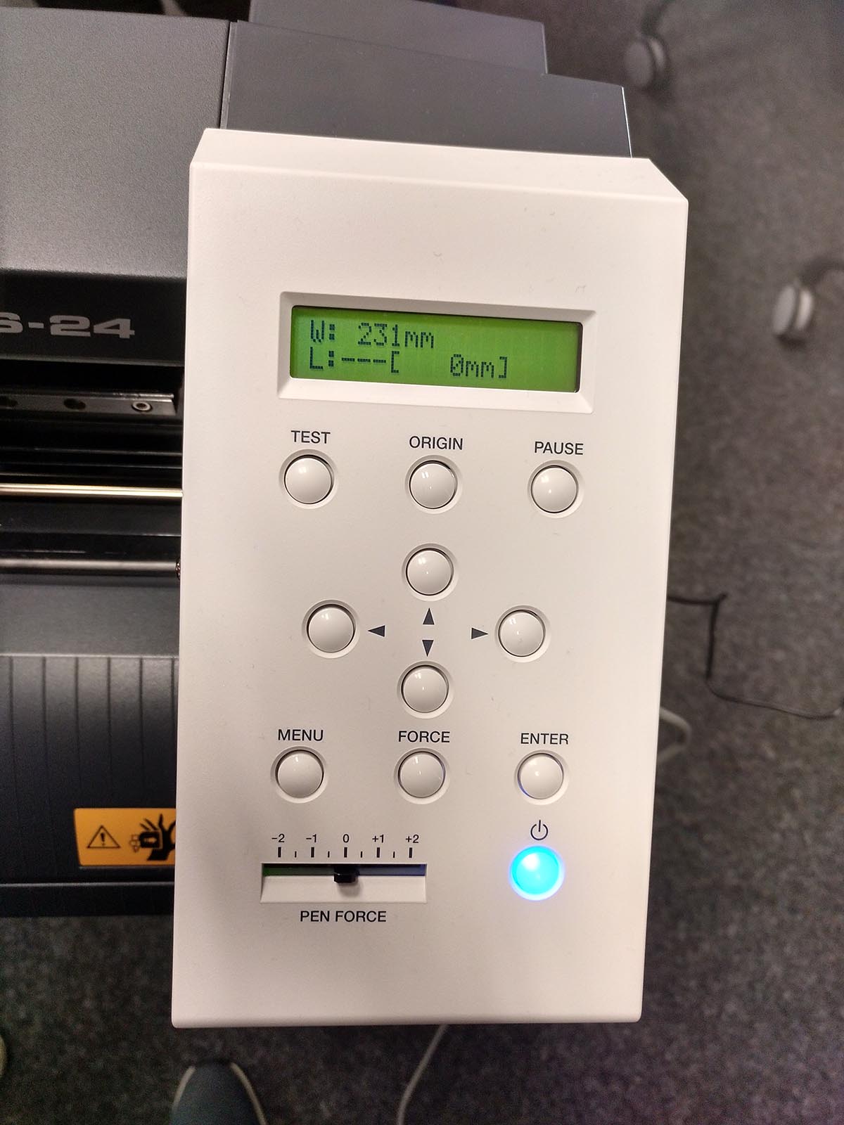
And displays it then on the control panel
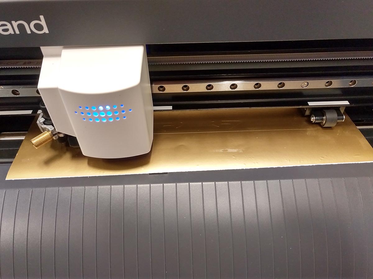
The vinylcutter while cutting
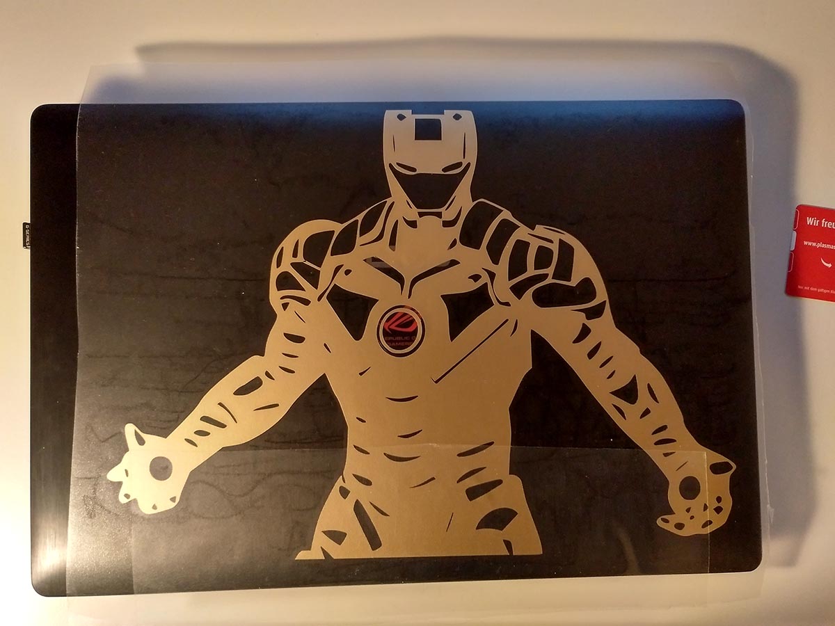
To put the sticker onto the laptop first the pieces that are not needed must be removed. Afterward, a carrier foil is put on top of the sticker. Then the lowest layer is removed and the sticker applied to the surface. It is also important to clean the surface beforehand, otherwise the sticker will rub off again.
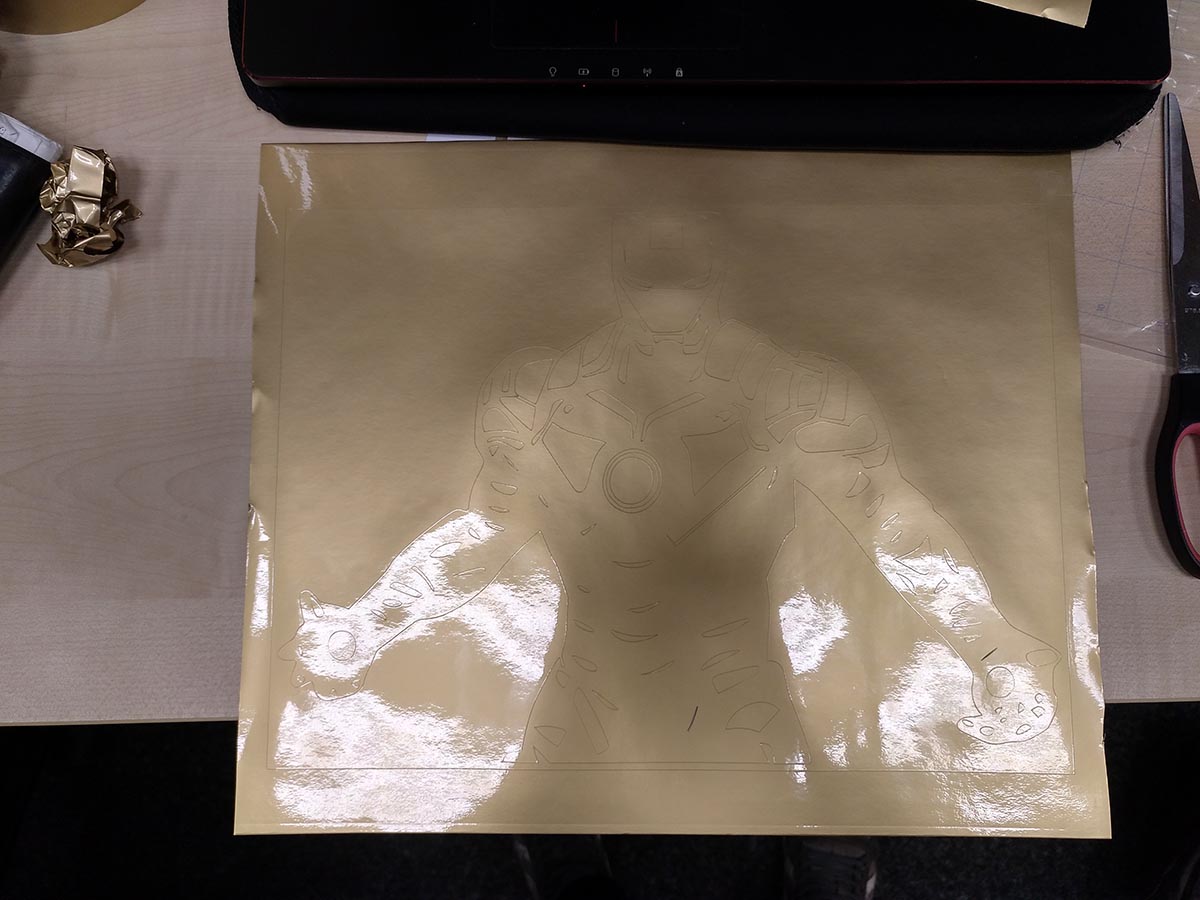
The foil with finished cuts
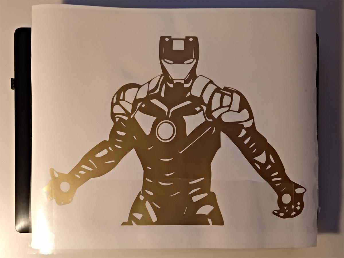
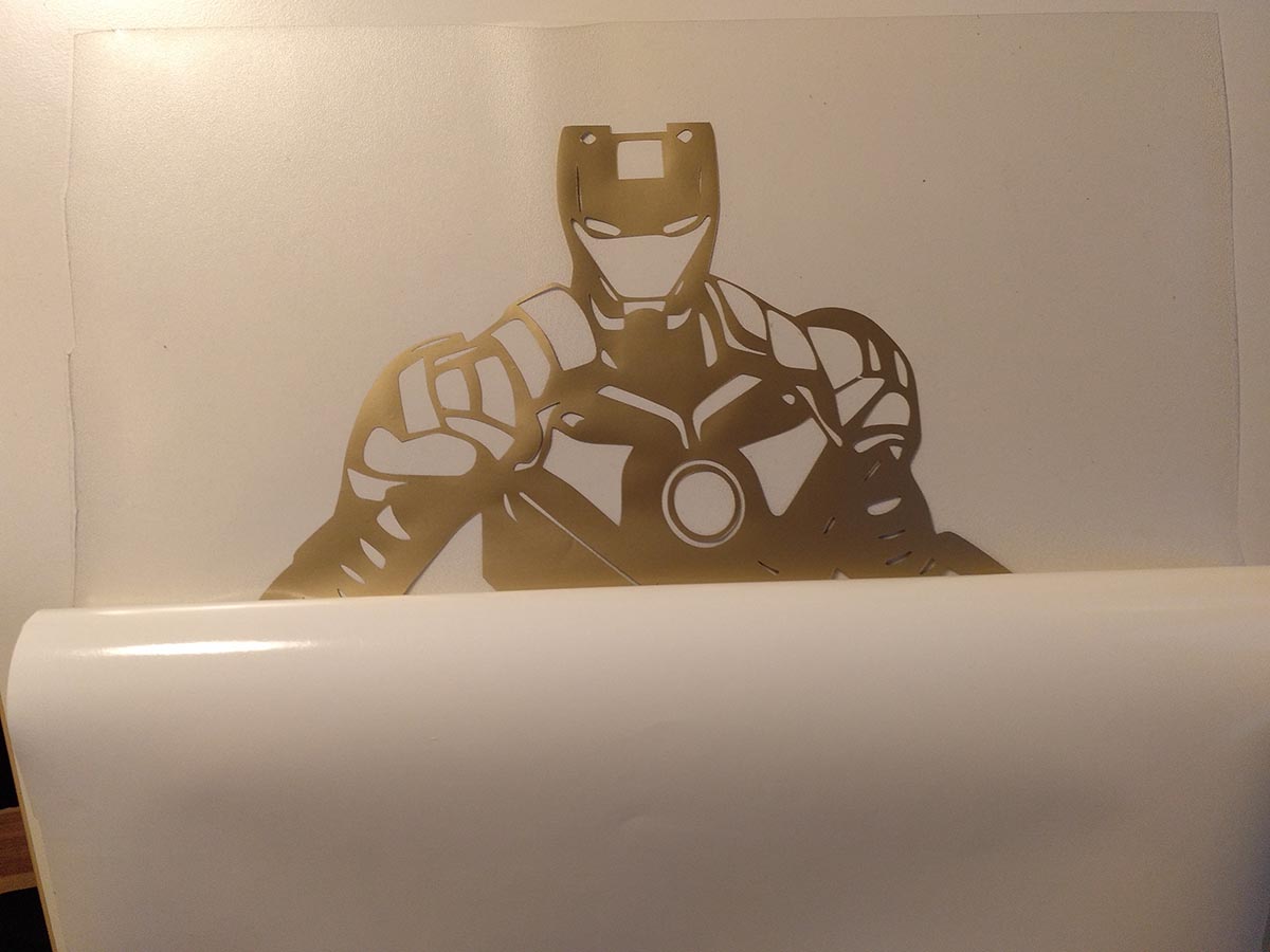
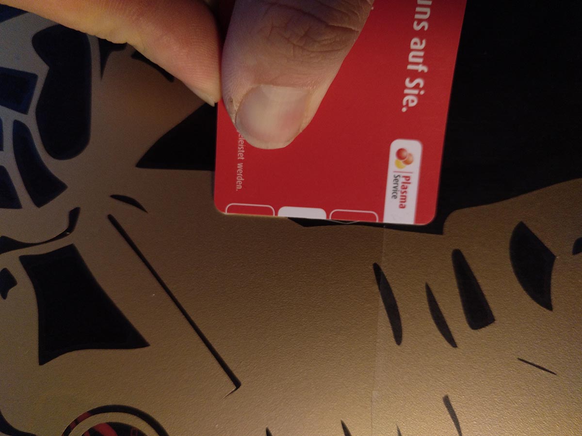
After removing the unnecessary parts
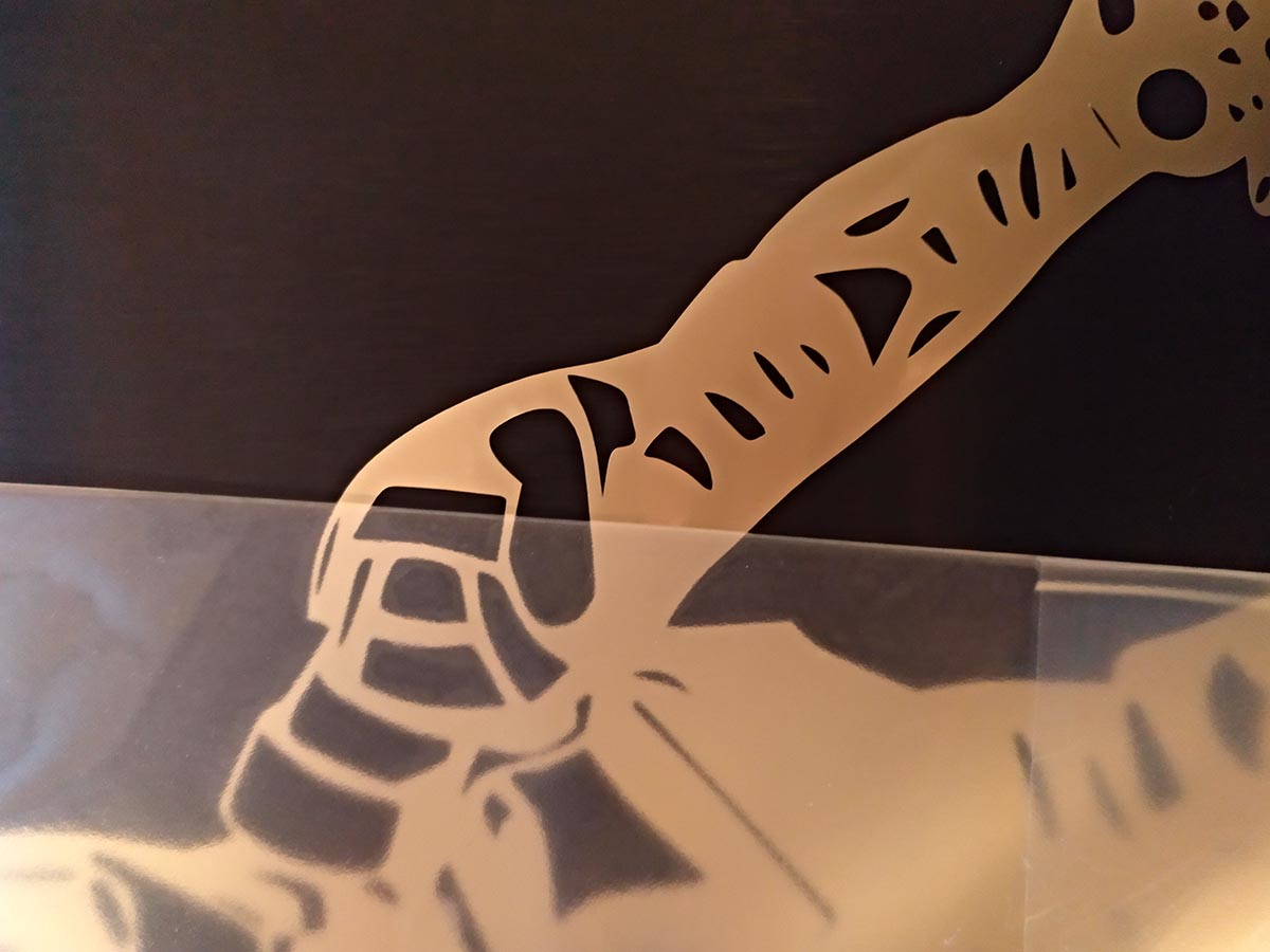
Applying the carrier foil
Put it on the surface
Trying to remove bubbles
Remove the carrier foil
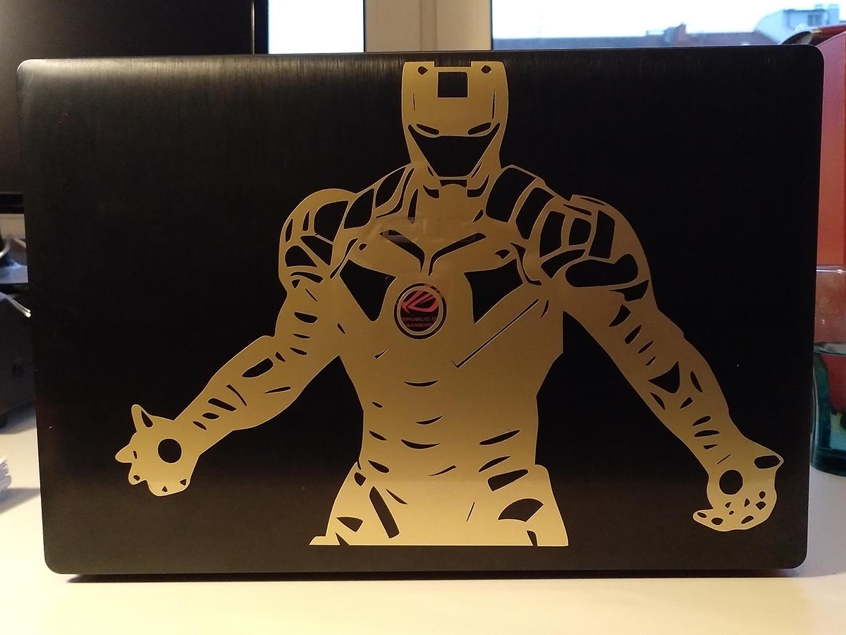
The finished sticker
There were some problems with the Calvin and Hobbes sticker, as it should be put on my phone and therefore it was cut too small. So in the first image, you can see that there is already some foil sticking up. Also, some cuts were not done quite right or missing in this cut. I think the problem is that the sticker was cut too small and maybe a smaller knife would help. When trying at a much lower speed the result was the same. Nevertheless I sat down and tried to get the sticker done, which was quite some work, but finally looked awesome.
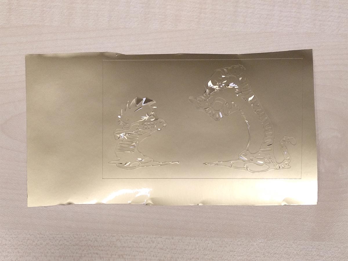
After cutting some parts are sticking up unfortunately
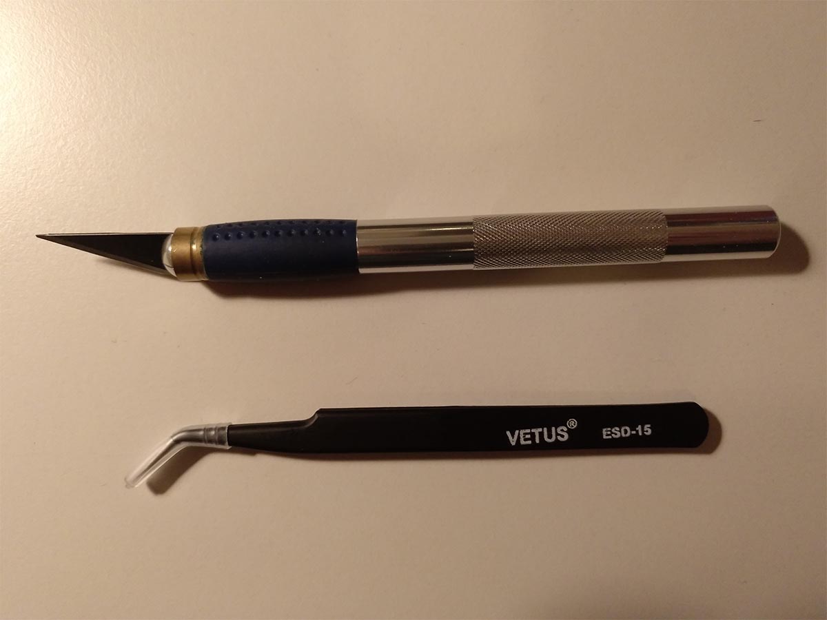
These two tools were vital to remove the unnecessary parts from the sticker
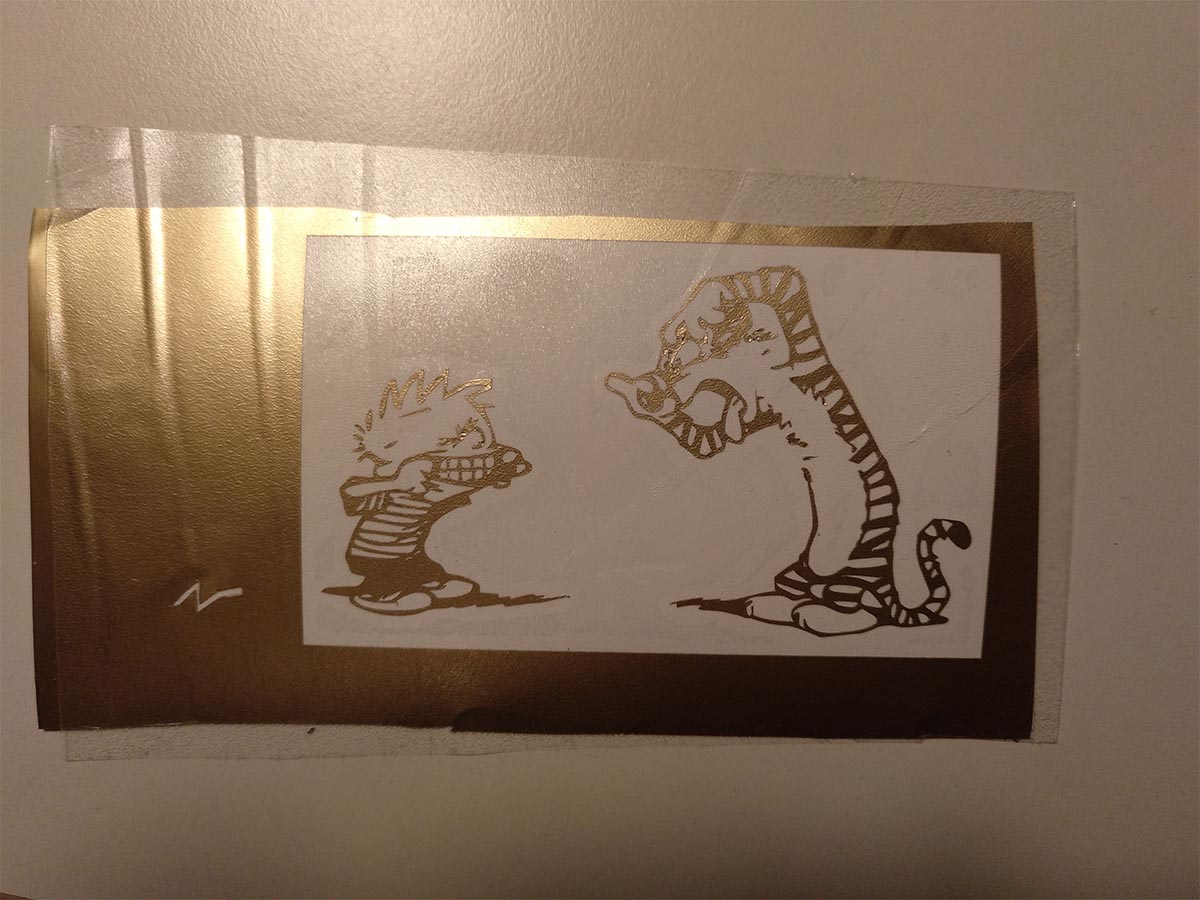
Everything removed and carrier foil put on
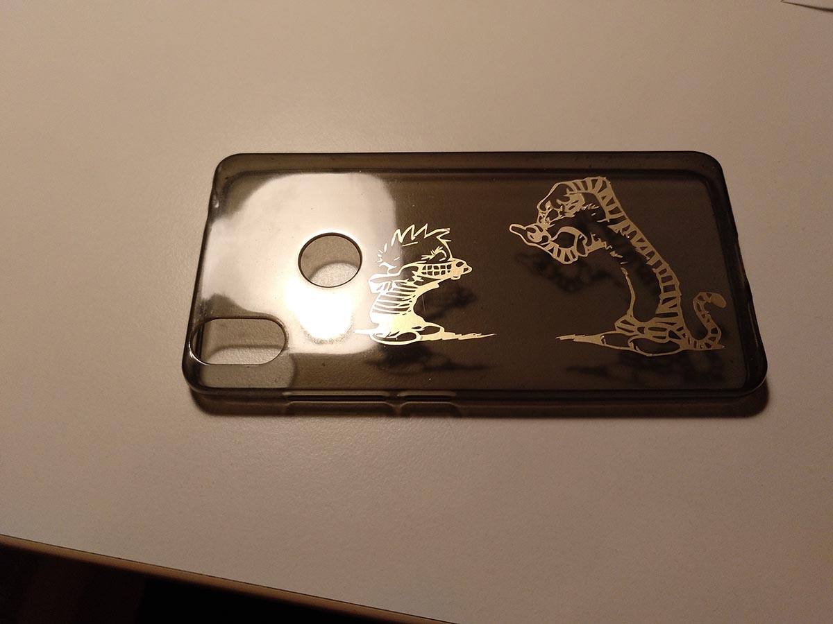
Smartphone cover with the sticker
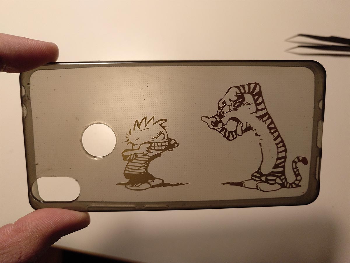
The sticker looks best with a bright background
Files
Here you can download the files created during this week:
The OpenSCAD parametric triangle file
The svg to cut all the triangle sides needed
The svg file of the deer
The x-wing flatfab file
The x-wing svg file for the lasercutter
The iron man svg file for the vinylcutter
The calvin and hobbes svg file for the vinylcutter