Seventh Week
ELECTRONIC DESIGN
ASSESSESMENTS
| HAVE YOU | TASK COMPLETED |
|---|---|
| how was your process using words/images/screenshots | YES |
| Explained problems and how you fixed them, including how you worked with design rules for milling (DRC in EagleCad and KiCad) | YES |
| Included original design files (Eagle, KiCad, Inkscape, .cad - whatever) | YES |
| NB. Also, if you make a board and it doesn't work; franken-hack that board (with jumper wires etc) until it does work, then make a new one with the knowledge you have gained. | YES |
GROUP PROJECT
| HAVE YOU | TASK COMPLETED |
|---|---|
| Use Test Lab Equipment in your lab for observe the operation of a micro-controller. | YES |
NEIL´S LESSON
Index
For this week´s assignment, the goal is to learn Circuit Design with differents softwares following this steps:
1st. When teach about "Creative Electronics", the first exercise that my students makes are the hello circuit without a micro- controller : I think is a good practice for learn basics electronics but we always use "Fritzing" for make quick prototypes and "Circuits.io" for simulation before solder. My experiences with both made me to decided start with :
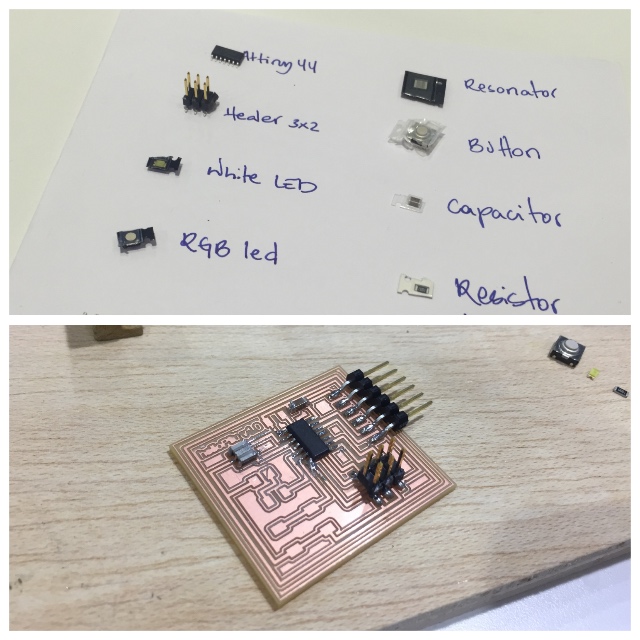
First of all i was looking at inventory all PARTS: (i love spent time there)
| Name | Inventory | Fab Library Symbol |
|---|---|---|
| 1X 6-pin programming header | 649-95278-101A06LF | AVRISPSMD |
| 1X Microcontroller: attiny44A | ATTINY44A-SSU-ND | ATTINY44 |
| 1X FTDI header : Powers the board and allows board to talk to computer | CONN HEADER 36POS .100 R-A SMD (S1143E-36-ND) | FTDI-SMD-HEADER |
| 1X 20MHz resonator : external clock. The attiny has a 8Mhz clock but the resonator is faster (increase the clock speed of the processor) and more accurate. | CER RESONATOR 20.00MHZ SMD (XC1109CT-ND) | RESONATOR |
| 2X Resistor | RES 10.0K OHM 1-4W 1% 1206 SMD (311-10.0KFRCT-ND) | RES-US1206FAB |
| 1X Button : (OMRON switch) | SW262CT-ND | 6MM_SWITCH6MM_SWITCH |
| 1X LED : LEDs have polarity - the side with the line is the cathode and connects to the ground side. | 160-1167-1-ND | RES- |
| 1 Resistor : (value 100k) | 311-100FRCT-ND | RES-US1206FAB |
GND : For ground each electronic component.
VCC : Power Supply of each electronic component.
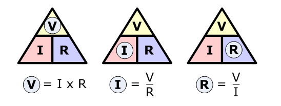
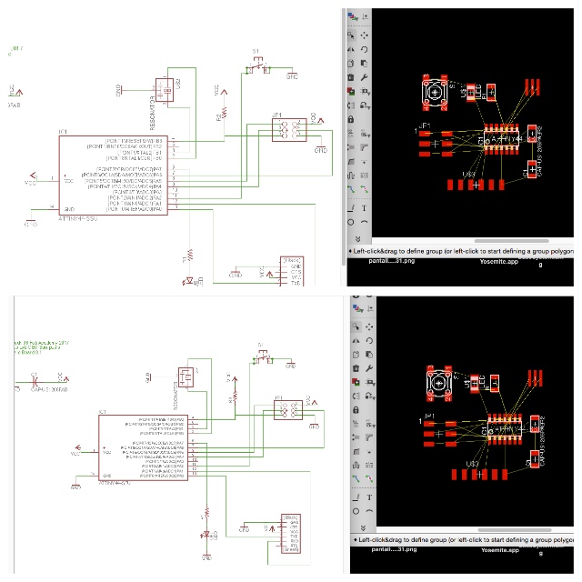
We must to calculate the current limiting resistor for the LED so we don't burn it. For that, we need the values from the Led´s data sheet and how power need for work applyiing the Ohmn´s Law we will have the results. Also I used an online calculator:
http://led.linear1.org/1led.wiz?VS=5;VF=1.8;ID=40
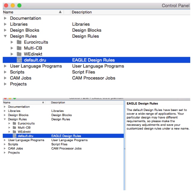
My LED , need a 100k resistor for workBefore open "Eagle" it´s necessary to download the Fablab component library and install inside the Software :
I Copied the library into the eagle´s install directory of eagle folder and renamed it adding "01"to "fab.lbr" for found first when i design later.
STEPS THAT I DID:
* Create a new project:
File -> New -> Project
Create a new Schematic and Board with the name helloPilu
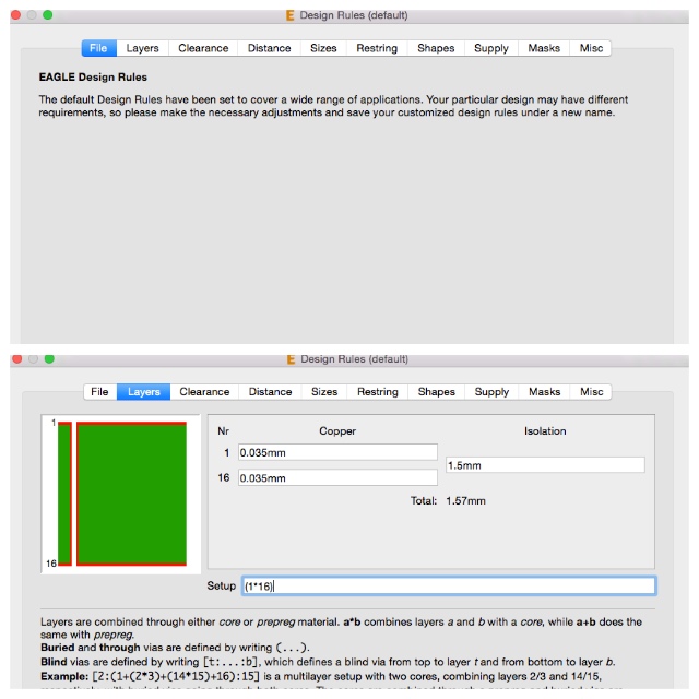
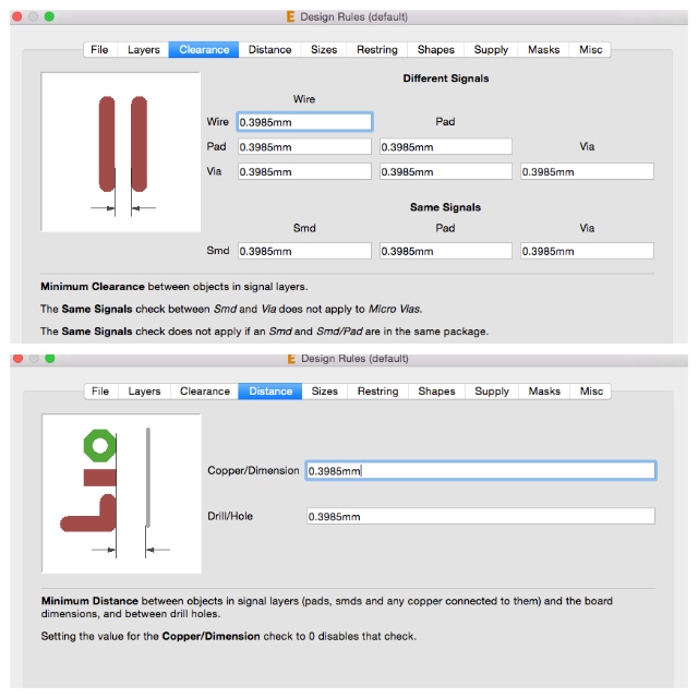
First for all i made my own design rules based in our´s fablab mill following basics:
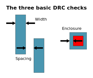
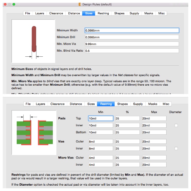
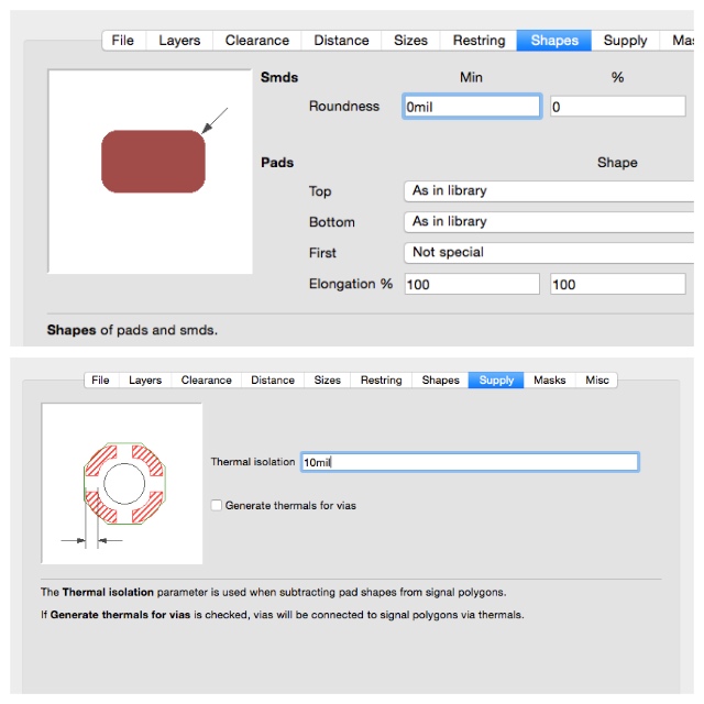
At Clearance is where you can adjust the electronic design to your mill. As you can see at my 4th Week, we use the Modela MDX20, so for 1/64 mill 0,39 0r 0,4 mm is perfect:
After this i was checking the components at fablib, the main component about the board it´s the microprocessor:
Here start my favourite part, how any component it´s expressed at library:
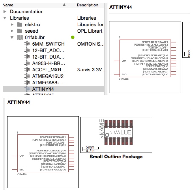
Looked the Fab Inventory spreadsheet which contains a list of all parts with codes and suppliers and checked with the datasheet of each component. For add a componet in eagle: press add on the command line or press add in the tool bar. Also, you can search the components adding asterisks.
Commands (use the command line or the menu):
For moving a group of parts:
1_select move
2_select group
3_right click + command
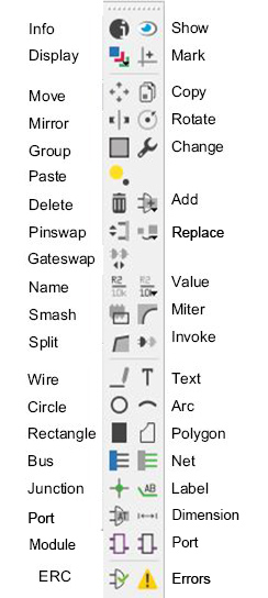
The green line are the NETs, for naming them in order to make the connection (the program will ask you if you want to make it), you have to use the commands NAME and LABEL. The command VALUE addes value to components (i.e. ohm rating).
I started the design from 0 for improve me and was fantastic because i had some errors during the process which learned to me differents things:
When you start a schematic you must create the board file and always work with both connected, if you close one, a warning message will to remember you.Don´t miss that!
BOARD DESIGN
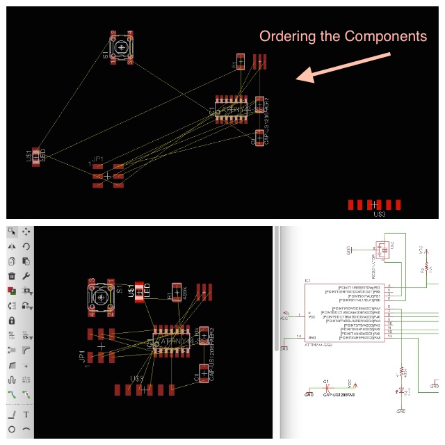
Once finished my schematic and check de electrical rules, i haven´t errors and continued with the board design. First, was order the elements :
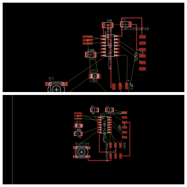
GRID : To edit the grid is very useful for correct the errors that the DCR give us. The rute have constraints given by the grid, so we can reduce the module of the grid in order to be more precise. The standard grid is SIZE 2.54 mm, but we can change it to dividends. The program also gives the possibility of be even more precise using Alt. I adjusted my GRID to 10 mil and 5 mil at Height by the advise of our instructor.
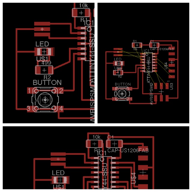
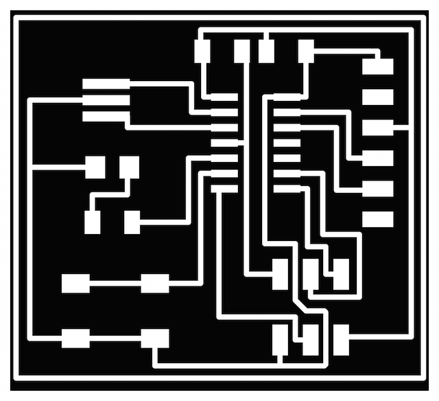
Routing : As you see in the pictures below i made differents design for practice more : At first i made correct FTDI routing but with the second i had a mistake at schematic and i didn´t check it and continued working on it like if it was correct. Here is where began all my problems with the helloPilu lived later.
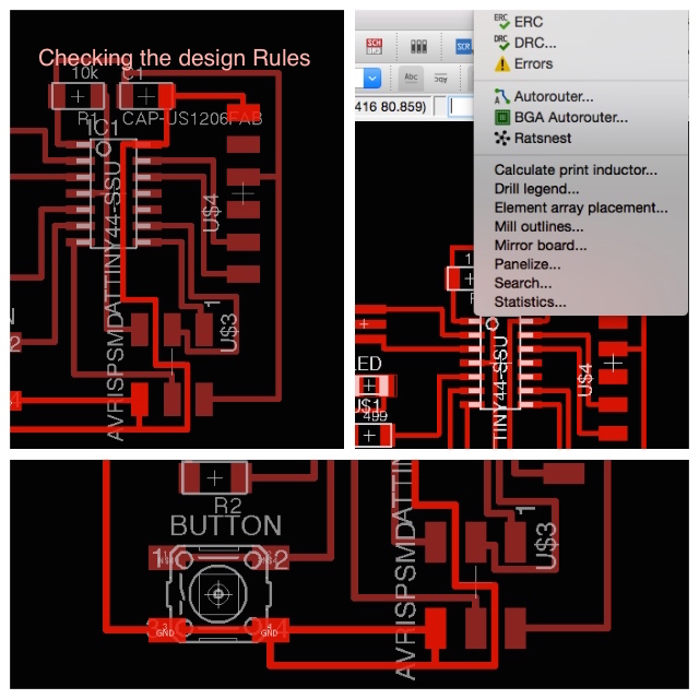
Before export the design as .png for mill i checked the DRC i found differents errors :
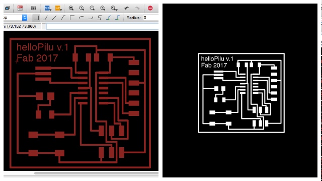
EXPORTING THE DESIGN & MILLING
When the design is finished I exported the traces as png file: I Turned off the layers, leaving only the traces and applied an apropiated resolution for mods :
FILE -> EXPORT -> IMAGE
Settings:
Full area
Monochrome / 1200 DPI
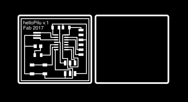
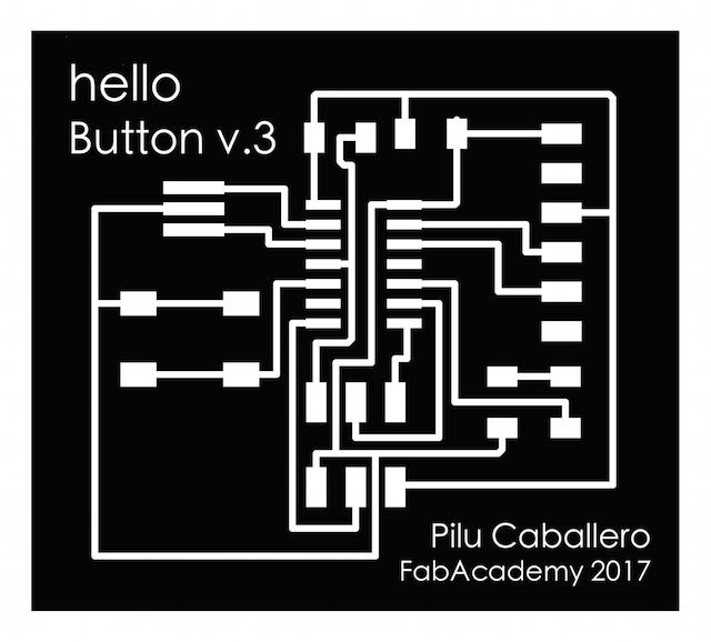
2nd MAKING THE OUTLINE FILE:
For make this i used a commercial software like Photoshop opening the traces file there, i edited image canvas size :
IMAGE -> CANVAS SIZE (In width/Height add +1.6, 0.40 each side (drill bit wich is 1/32 inches = 0.79 mm).
This line is colored by white and with "magic Tool" and selecting the white rectangle, i applied the difference while white color it´s selected.
With right click on mouse, filled the rectangle with black color, inverse and fillet with white again. Here it´s the result, my design ready for mill with the modela at ./mods
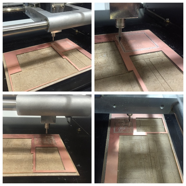
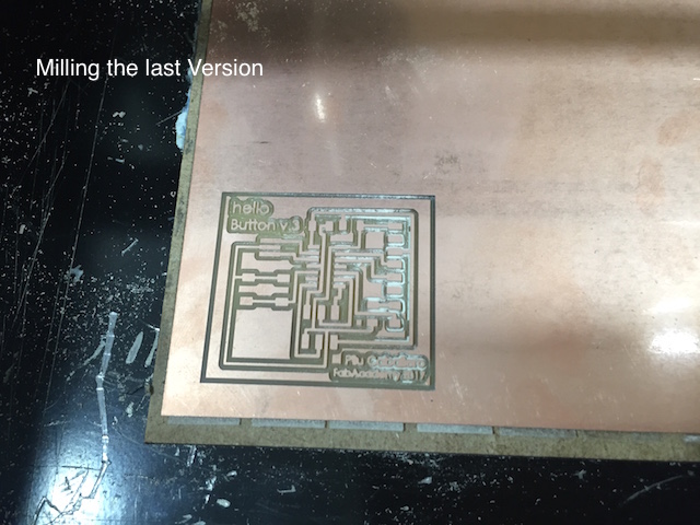
.MILLING TIME
3rd The assignment´s last part was MILLING our new hello boards with the Modela Milling Machine:
I used Fab Mods for make this : (See Week04)
This task was simple for me, later, my classmates had differents problems with it but i don´t know why it works fine for me and for once i felt like a lucky girl with no good results :
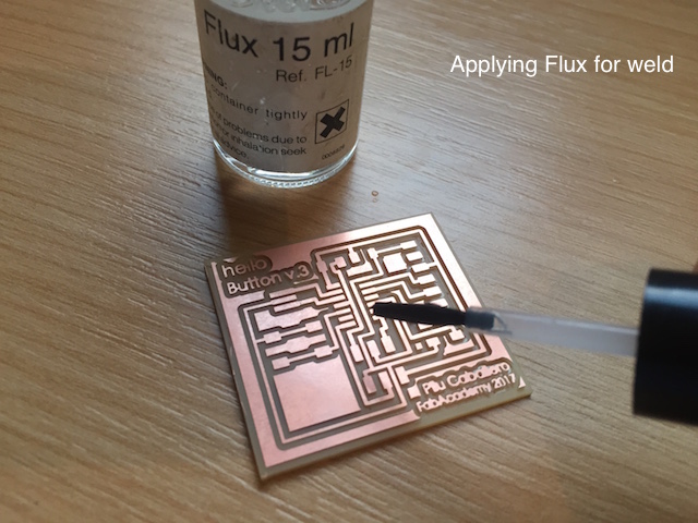
WELD TIME
WELD TIPS:
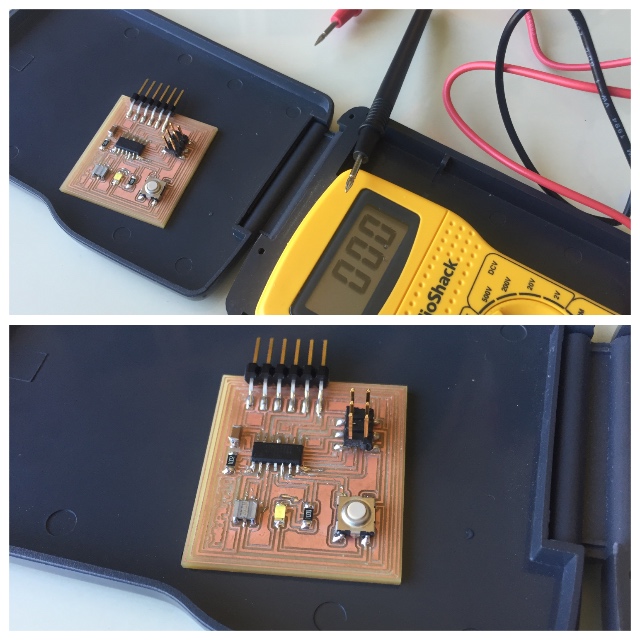
Once i finished, taked a train to Seville for resolve papers and carried with me the hello board with the goal to check with the first multimeter i bought when started to study "Creative interactives" at New York...
The multimeter doesn´t work correctly but i know i have a problem with differents things, i think i lost something at design, but i can´t to try more things because i haven´t solder here and for that, i decided start to design my own circuit board for my Final Project Proposal.
When back to my fablab, decided try to resolve problems with my helloBoard, there found the mistakes commented and some with electronics like the led, our instructor tell us that the white led have deffects and decided change it with another which use the same resistor value. After i try to make jumpers for work with it but nothing happens. How i had some difficulties about to measure continuity with the multimeter for not clear traces at my board. Talked with my instructors and explain the errors and decided make new one after correct my design at Eagle.
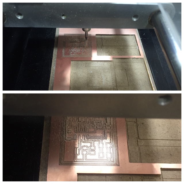
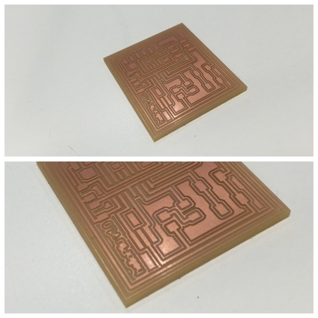
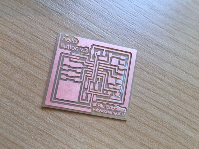
WEEK PROBLEMS : MILLING
Here is my hero pic about my first "helloPilu Board" and you can see below, how i forgot put offset to 0 at .mods for fill my board... as i talked with my Guru from Fablab León, Nuria at the last rewiew, i will never forget this thing never more.
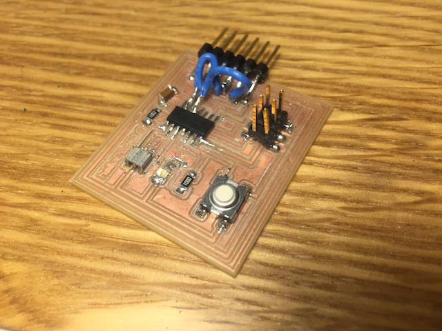
2nd ATTEMP
1. For solved things with my board i redesigned it at Eagle and with my boards ready, i prepare the files at Ps :

2. Milled again at the Modela using .mods :
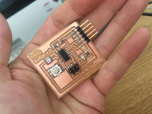
3. And welt properly :
4.After i checked all with my multimeter i decided to connect to my computer and test if the USB Port appear at my Hardware System Information and my board looks there so is ready for programming the next assignment.
For this attemp i soldered the hello board modified quiet and hope but when connect to my Fab Isp for burn the bootloader and program the basic example for blinking my led. But i didn´t made this because was imposble and decided to try Electronics design for my final project.
RESULTS
LEARN I GAINED
As i had to repeat the processes 3 times, i memorized all the processes for next assignments but i´m sure that i will have other mistakes in future... I know that i must to made a C program but i resolved this assignment some weeks later.
WEEK FILES
MODIFIED FILES
GROUP PROJECTS
For this year we must to make some practices in group so Lucio and i decided use our boards for use the equipmente present in our lab and make some testers.
How contribute for this task group? First of all i organize the works for to do in time, also develope the web site for this week explaining there all things worked together and individually.
I also watched some basic tutorials about how to use the equipment. I have experience with multimeters and Regulated Powers Supplies but never use an oscilloscope before for observe the operaton of a micro- controller under my opinion, a good practices for learn better about micro- controllers, electronics circuits and design and of course, for know if something is not working and why.
So for see the experiments made please visit our Group Project´s website here :
WEEK CONCLUSIONS
During this week all i learned was new so now i know how to use Eagle, i learned more about possible sensors for my final project. I learned of course about design and electric rules. Trought my problems solved i obtained new skills as a franken! . Never will forget the correct offset for mill my boards.
THE KITE BOARD
For the Kite Board i found references at Spark Fun web, i must to design something like a weather station but with less components. I had a doubt about the type of board i must to design and ask about it to my instructor Epifanio for start in the right way. My doubts was about if will better to design a shield or differents boards making differences with imputs and outputs. I love the idea to design a shield but Epifanio´s opinion is important to me by my unexperience with the use of sensors i will to use. (Never used barometrics, CO2 , temperature or humidity sensors...) so for that i start step by step with the study of these and what they need to works correctly. I love this moment, each night can to research about them and my learning curve after this assignment increase in the way to spent bit time for this.
I started with the Humidity Sensor, here you can download his "datasheet" :

Later my meet with my instructor Epifanio, decided to start with the redraw of FabDuino a Fabable Arduino Compatible Board with an optional 8mhz resonator (16mhz also works but requires different bootloader/fuse settings). This is probably the only non-standard inventory part, but is similar to the 20mhz resonator and very important if a will do faster serial comumunication. The digikey part number is 535-10004-1-ND. You can always build the board without it and add it later.and found really usefull the design about the FabKit v.1 from Saverio Sili :
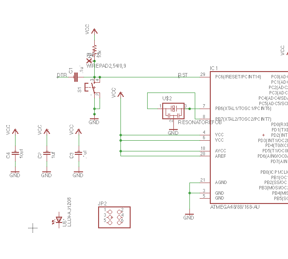
The part list for buy components at Inventory is :
| Name | Inventory | Fab Library Symbol |
|---|---|---|
| 1X 6-pin programming header | 649-95278-101A06LF | AVRISPSMD |
| 1X Microcontroller: ATMega | ATMEGA48/88/168-SSU-ND | Atmega48/88/168UA |
| 1X FTDI header : Powers the board and allows board to talk to computer | CONN HEADER 36POS .100 R-A SMD (S1143E-36-ND) | FTDI-SMD-HEADER |
| 1X 8MHz resonator : external clock. (increase the clock speed of the processor) and more accurate. | CER RESONATOR 8.00MHZ SMD | RESONATOR NOT AT THE INVENTORY |
| 2X Resistor | RES 10.0K OHM 1-4W 1% 1206 SMD (311-10.0KFRCT-ND) | RES-US1206FAB |
| 1X Button : (OMRON switch) | SW262CT-ND | 6MM_SWITCH6MM_SWITCH |
| 1X LED Green: LEDs have polarity - the side with the line is the cathode and connects to the ground side. | 160-1167-1-ND | RES- |
| 1 Resistor : (value 100k) | 311-100FRCT-ND | RES-US1206FAB |
