Sixth Week
3D SCANNING & PRINTING
ASSESSESMENTS
| HAVE YOU | TASK COMPLETED |
|---|---|
| Described what you learned by testing the 3D printers | YES |
| Shown how you designed and made your object and explained why it could not be made subtractively | YES |
| Scanned an object | YES |
| Outlined problems and how you fixed them | YES |
| Included your design files and ‘hero shot’ photos of the scan and the final object | YES |
NEIL´S LESSON
Index
Week 5 3D Printers Meets ThermoChromics Filaments from Pilu Caballero on Vimeo.
WEEK 5
I have some experiences about 3D printers because last year a built a pair of Prusas i3 and actually use them with my little students. The experience with this kind of models, i could to define like a fight: Fight with electronics, fight with parts, fight callibrating... but i learned a lot of things with the Prusa and his Merlin Firmware. In my opinion, 3D Printers are really useful for a lot of tasks and they advanced in last years in amazing ways, but print is not just send a file and click... I have also used models like : Hephestos 2, Whitbox and Ultimaker. Our FabLab have some 3D Printers, MakerBots "Replicator 2" . As I have never used one, it seems like a fantastic opportunity to learn and experiment with another model and the use of new materials.
This week we have to practice in group too for learn about angles, meshes, polysurfaces... For made this we use open designs from Thingiverse and any personal design where we can learned about things. As the last assignment, we make a webpage where you can see all our steps followed, processes,results and conclusions.
I developed a web group which you can visit here :
For clear things we have care about :
Model:
Accuracy:
Machine measures: 285mm x 153mm x 155mm.
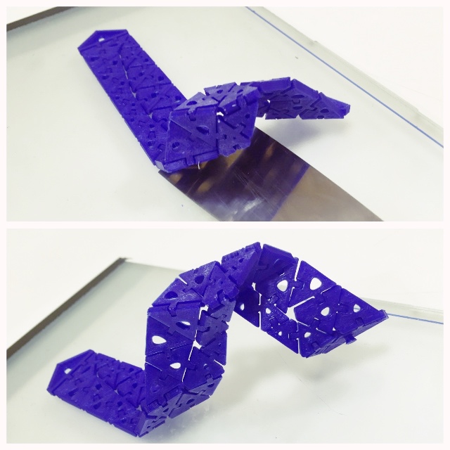
Tolerances: When printing pieces that are hooked the tolerances are very important :
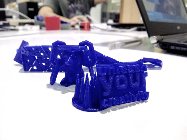
Here you have a pics about some things made it :
During 2018 i had the opportunity to make more practices described at the web page i developed too so here is the link for know more about some samples i made for my Fashion Designers Students about how to integrated 3Dprints on fabrics:
2nd. How i have the opportunity of teach about wearables and sewables at workshops and lectures at Universities and Fashion Design Schools and in this assignment we must to practice differents things with OpensDesigns, i decided use the first part for make a future Wearable Workshop with 3D Printers.
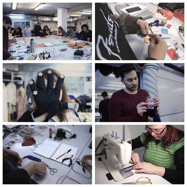
People love bring things to their home when finish this shorts courses so i think it´s a great idea introduce to 3D Prints for wearables with the practice of simple things follow the steps of the assignment.
My workshop, could be :
As my students will have to practice quickly things with differents tools, a cool idea is the practice of OPENSOURCES DESIGNS. Of course they can look free things at Thingiverse and others famous platforms if want to print anything else but for that and from long time ago, i use a standalone from a people who i respect to much because i consider them pioneers in the use of Processing (another tool who i love) for make real things. They are "Nervous System" and always are mentioned on my Referents Units.
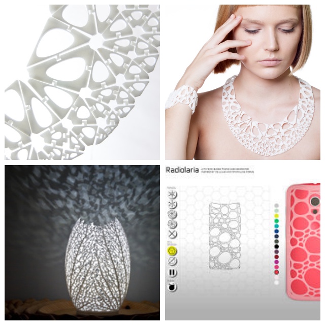
When people sense with using of some code lines can make things so cutes, they want to know more inmediately.
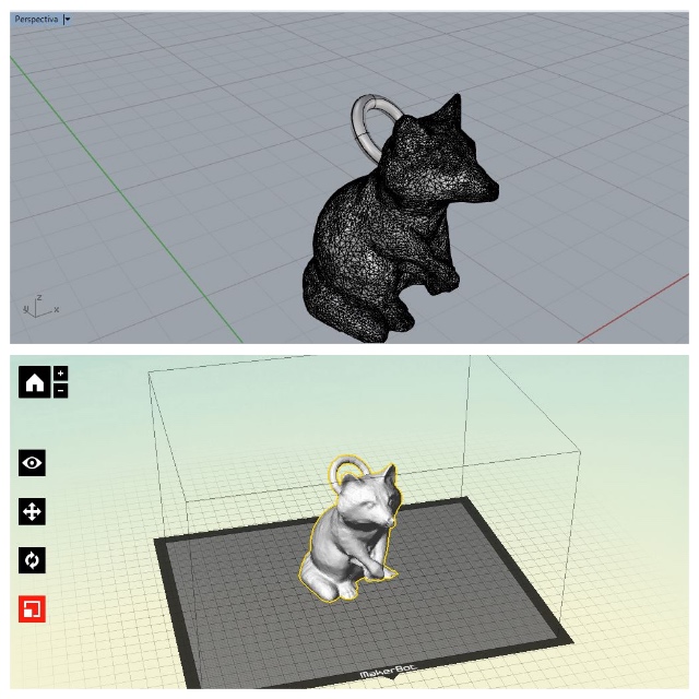
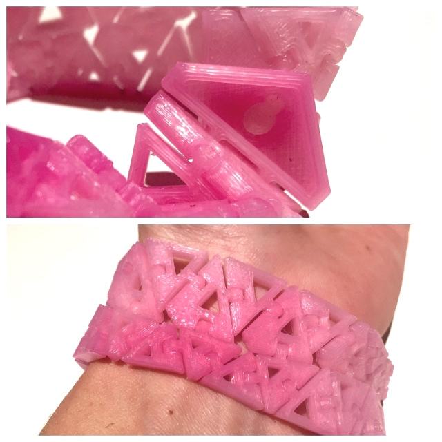
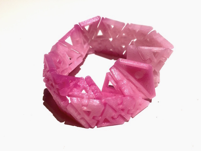
So for the practice, they can use "Kinematics Generator", a simply and intuitive app which allow select sizes, models, colors and apply a bit deformation for custom designs.
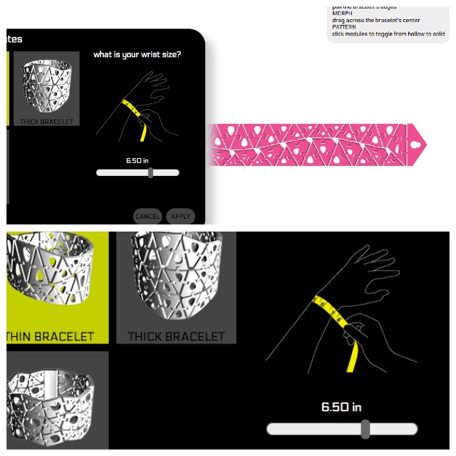
For make a bracelet like this :
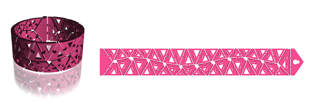
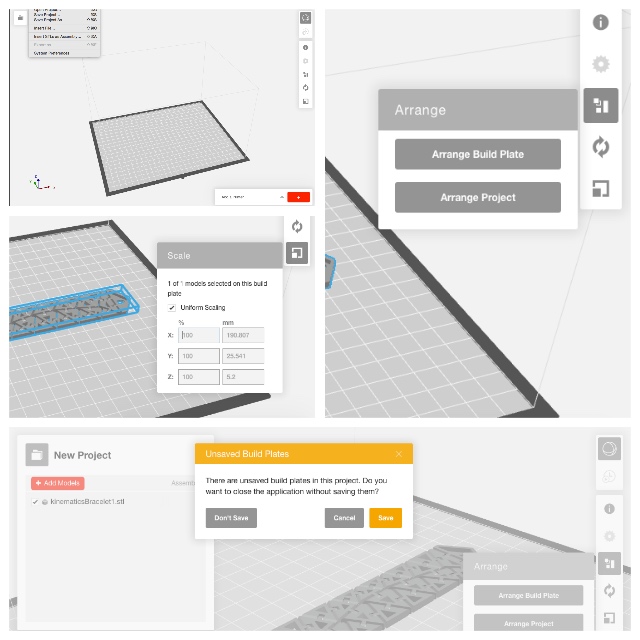
The last part of the workshop might to be an introduce of 3D printers softwares : The app export an adecuate file with .stl, they just will have to prepare their files at there, learning about basics like fills, sizes, rafts, numbers of pieces, dimensions...they can have a cool bracelet spend bit time.
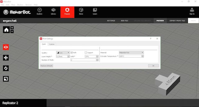
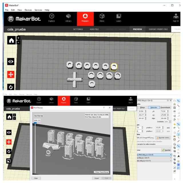
Maker Bot Software is also simply to desktop application that allows us to prepare, manage, and monitor 3D prints.
The first thing to do is placing the PLA filament, for this:
1. I placed the PLA roll support because the thermochromic hole´s roll is smaller than common PLA filaments.
2. Put the roll in the support provided upward.
3. Put the filament inside the plastic tube that goes to the extruder.
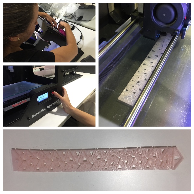
For load the filament at the MakerBot, press “Utilities” at the display, "change filament", and "load". The printer begins heating, once the extruder is beeping introduce filament at the top extruder, press the lever on the right side of the extruder for help and the printer is ready.
To unload the press filament "Utilities", "change filament" and press "unload". When the filament is hot , push again the lever and extract.
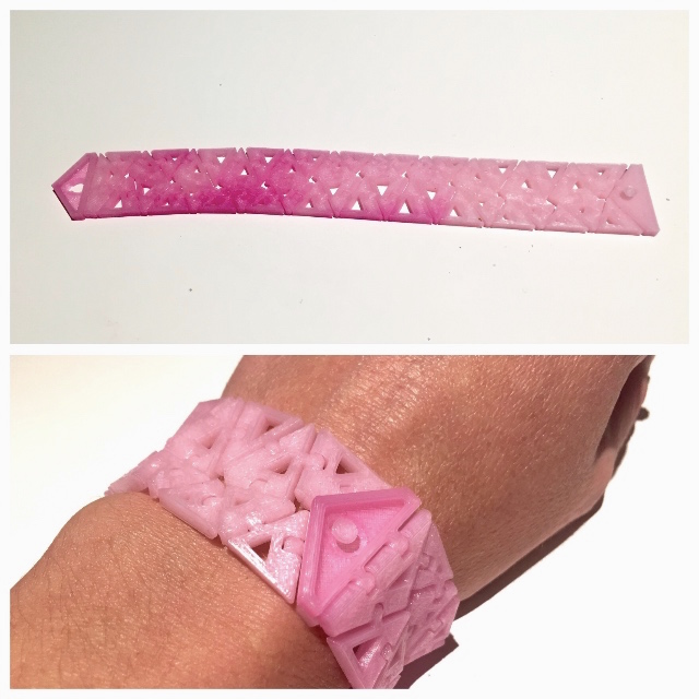
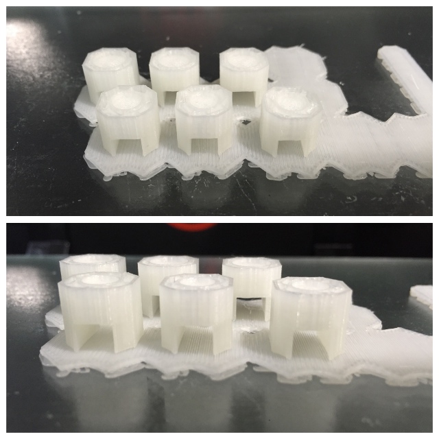
The use of thermochromic filament wich i bought last summer works on interestings ways. You see at pictures below how i didn´t print to the best quality. This Filament it´s most expensive than common PLA filaments but is really effective for teach interactives with new materials.
| Material | Profile | Temperature | Speed | Support | Raft |
|---|---|---|---|---|---|
| "Chamaleon 3D Ink Filament" from printm3d.com. The model used is called Rose Red-Touch and works changing colors after the object is printed starting at 30º | |
It depends on the material. For PLA 220º our makerbot have 230º by default but how this is a test, I decided to print to 210º. | Without changes | The machine cannot print on the air and have supports for resolve this but i can print this piece without support | I usually use it but not for this piece. Under my experience, the design works better without it. |
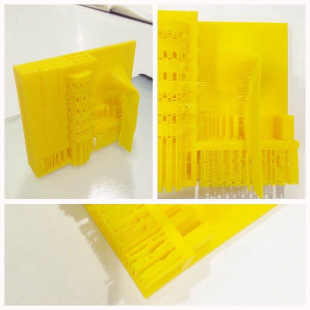
I want to show you another actual process. As i mentioned at my 2nd Assignment, i work with 101Lab from Granada on differents ways about "Design and Digital" Fabrication. We make interactives but are focuss on product´s develop and other interesting things, reseraching solutions related to our environment.
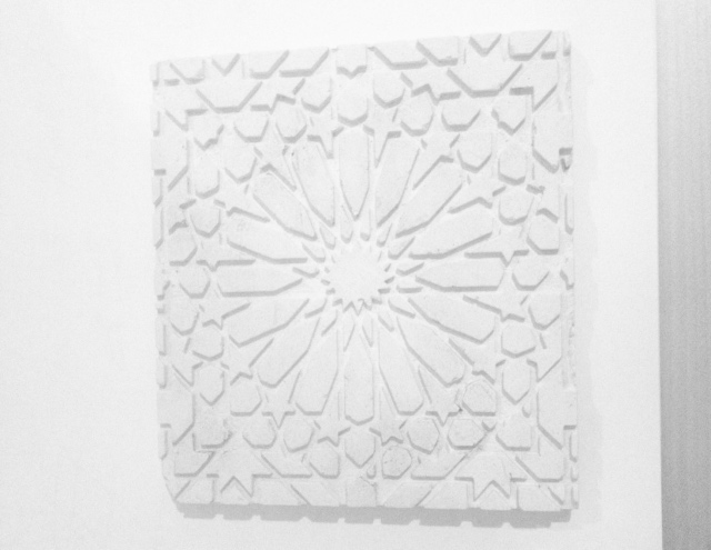
Here you have one of those things : The idea is Design an adecuated Mold for help in the process of restore our architectural heritage. We´re Andalusians and it´s inevitable to think kinds of solutions that help to the historical preservation. For this reason our design is based in traditional Andalusians Tiles.
I meet you the hand of my partner, Pedro, yes, the designer friend who forces me to draw pieces of things for learn at the weekends ... surely my instructor Epifanio would like to meet him!
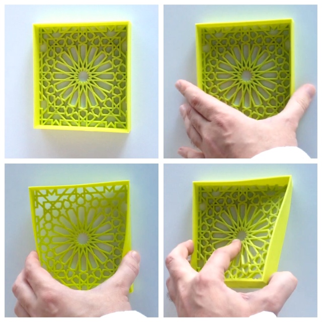
We use an Ultimaker 2for print the mold and the filament used it´s called "SmartFlex" from 3D Smarts Materials the company where Pedro works.
As i have the habit using PLA filaments, working on a design with flexible filaments is a project that caught me from the first moment, for the moment, Pedro it´s learned to me a lot in the use of these filaments. The Designing process was long to obtain nice results but still working... Sure the "Molding and Casting" assignment will to help us! Stay Tuned!
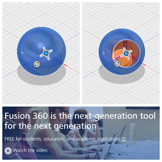
3rd. The next part of the assignment consist in design a small non substractively piece for print and i decided to start designing with Fusion 360º . I never use the enviroment but thought that design a simple ball with another inside it would not take me long time :
When back to home from the fablab, i found my ancient dog really sick. Went to the veterinary and this task spent all my time this weekend. On sunday, wake early and decide simplify my life with the assignment and try to design a piece with a tool sometimes i use :
Designs are described withing a text file, that it parses to generate and show 3D shapes. The mouse is only useful to view, zoom and rotate around the generated shape.
CSG and incremental design
Openscad and CSG in general works the exact same way ,the process an artist follows when he works with clay, except that each of the step is described with names and explicit commands, that are applied one after another.
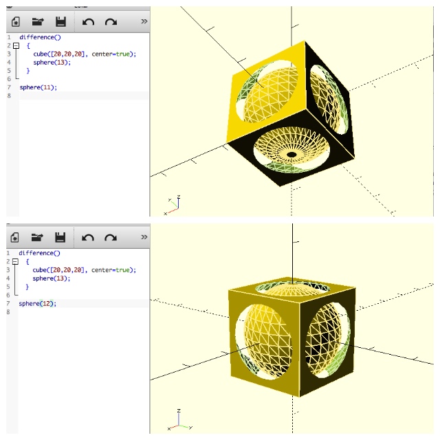
1. First i create a new file and draw a cube with (20,20,20) > each value is for x, y and z and centered it at the plane
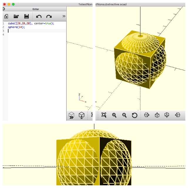
2. As you can see at the first pic, Later i draw a sphere too at the same plane with the size of 14 mm
Openscad language mostly looks like the C computing language, or even Java, Javascript or... so it works with a syntax like them. Typos are forbidden, as they generate dreaded "syntax errors". It Openscad doesn´t understand what you are telling to him check the "console" . This is where you read the erroneous line number and you can fix it at the editor.
Each command you give to Openscad must end with a semicolon ";" , same thing at Arduino IDE or Processing. This is to tell Openscad that it has to do something at this point, while the former elements are preparing the work to do, like positioning the item or applying a transformation and eventually telling the shape:
3. For make a preview about the model just select at the contextual menu Design > Previsualization :
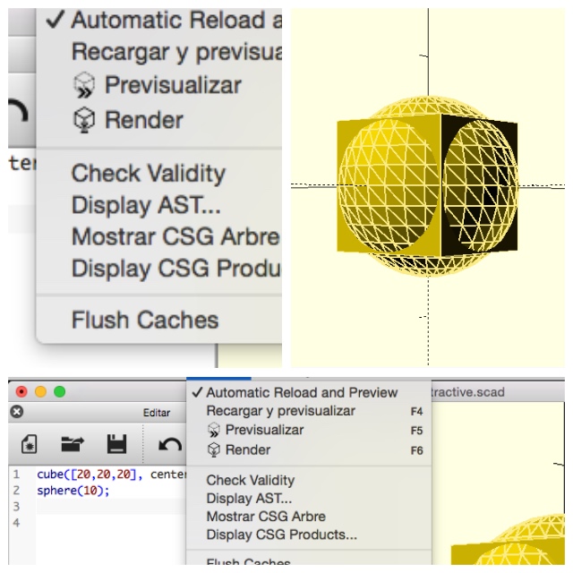
4. As you can see, the ball inside is bigger than the cube, so i reduce the size and after made the difference between both :
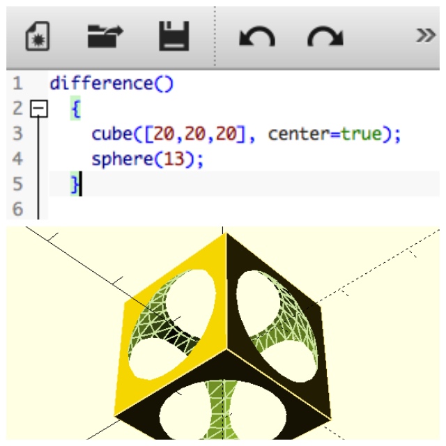
As much as you can add one primitive to another, you can also subtract one shape from another, effectively carving the first shape by means of the second shape.
The "difference( )" operator also applies on a number of shapes, just as the union above. Now the order is important: the first shape is created as usual (positive shape), and then are the shapes of every other subsequent item subtracted from it removing material each time.
The danger of CSG subtraction: dreaded undefined surfaces. Be carefull with that.
When you substract a shape from another one, you must make sure not to leave any wall or surface with no thickness. This happens often if you do not take care of it.
e.g If you want a cube with a cylindrical hole through it. The right way is idea create a cube and then substract a cylinder from it.
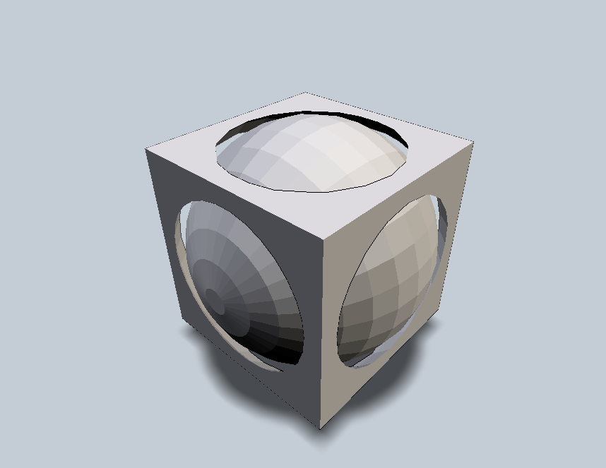
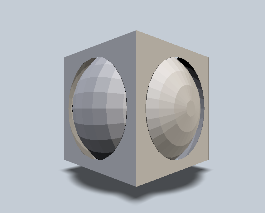
5. For fisnish i draw a new Sphere at the center plane adjusting the model volume before render for export.

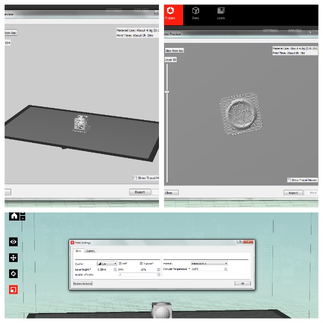
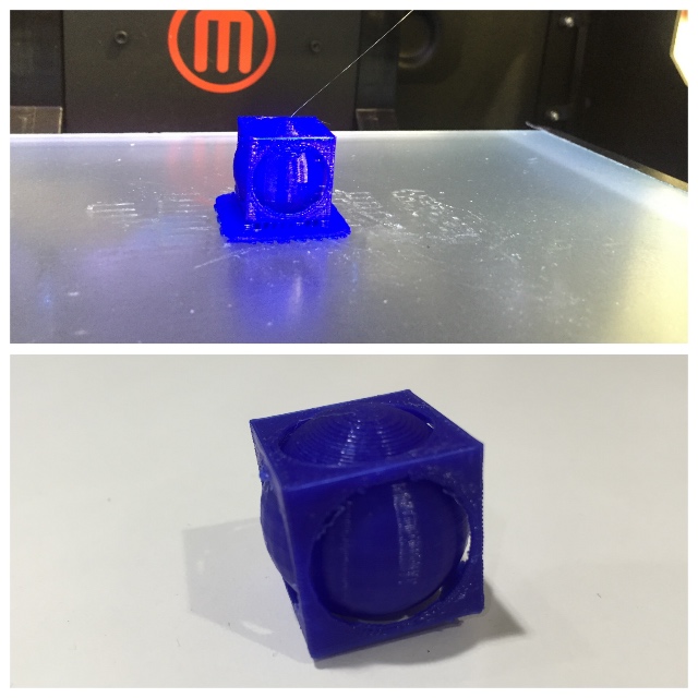
WHY JUST TO MADE WITH 3D PRINTERS :
Because the model is just few mm and for the moment the tools and hands should to be ultra tiny and sure you spent a lot of time sculping a piece like that. The printer help a lot making the object by layers really faster too.
3rd. For the last part, we must to practice with scaner for scanning objects,persons animals...
A 3D scanner is a device that analyses a real-world object or environment to collect data on its shape and possibly its appearance. The collected data can then be used to construct digital three-dimensional models.
Contact 3D scanners probe the subject through physical touch, while the object is in contact with or resting on a precision flat surface plate, ground and polished to a specific maximum of surface roughness. In our lab we have Sense Scaner model.
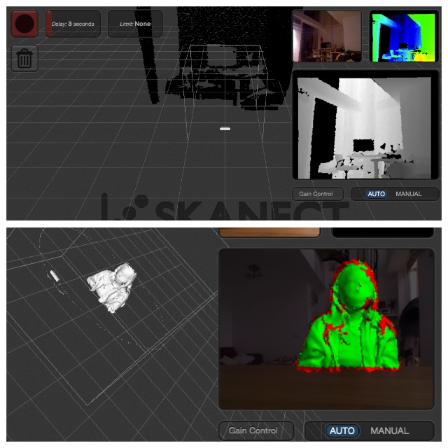
First did was learn about our fablab Scanner called "Prime Sense" my classmate Dani was testing it with me. As he have Windows System and we was testing the Prime Sense Scaner i was learned the process withs this Operating System first.
After we downloaded and installed the Prime Sense software, the use of it was really simple but the lightning conditions affect us to our testers lossing tracking when was working. This lost points can be adjust with the software but is better use it with right lights for have for the begin a nice complete scan.

I have further experience with IR Cams and Computer Vision and the scaner works similar, gets information from the object and from around so the quiet use of it is recomended.
How i have experience with the Kinect for performances and stage interactive video purposes from his hacking by the gallician guy few years ago, i decided use mine like a scaner.
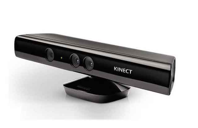
Microsoft Kinect is an affordable 3D scanner which uses infrared laser light with a speckle pattern. Basically The Kinect uses an infrared projector and sensor to scan objects.The technique of analyzing a known pattern is called structured light.
This 3D Scanner combines structured light with two classic computer vision techniques: depth from focus, and depth from stereo. Using this 3D scanner is possible to get 3D meshes out of real scenes in a few minutes and you can to scan big models fast and precise.
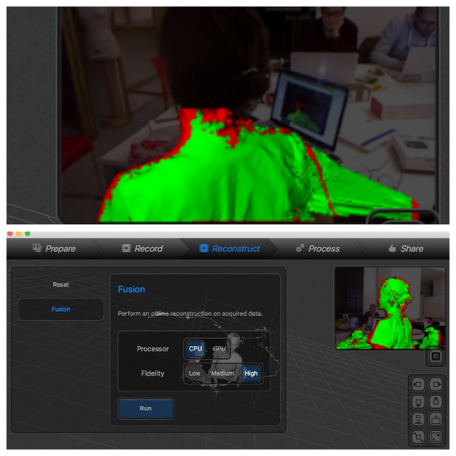
I used this 3D Scanner to obtain an accurate mesh of part the basic settings :
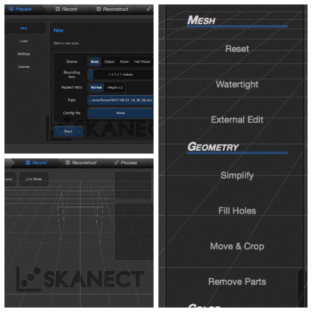
When I installed Scanect my GPU not supported so i decided to try on my desktop computer with my self and my dog but without good results.
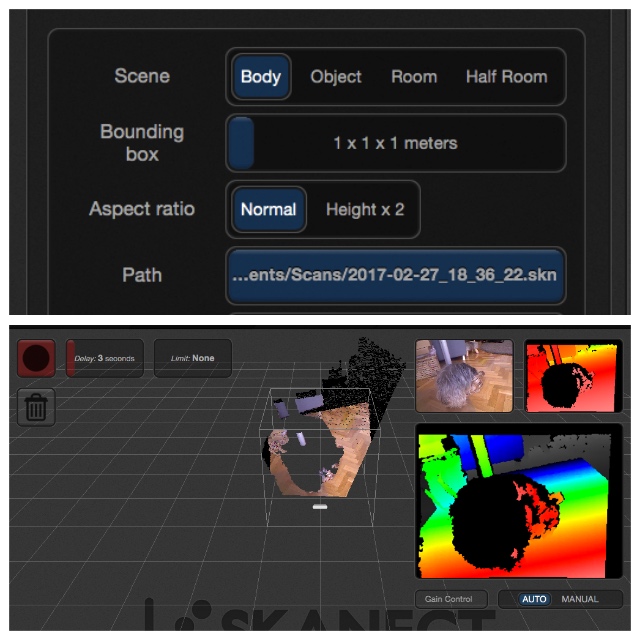
At Tuesday my students from IED wont to know more about scanners so i decided practice with one of them, so thanks Juli from Abismal for be my model for this time :
1. Getting image Juli´s body
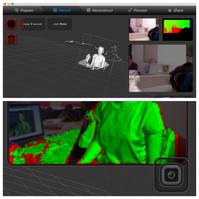
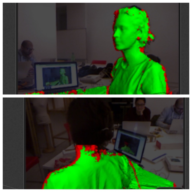
2. Restoring tracking lost
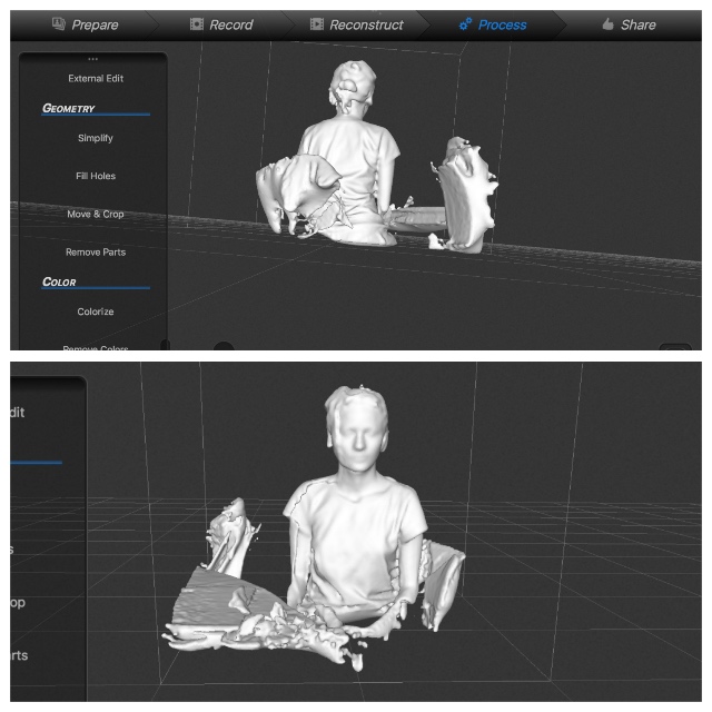
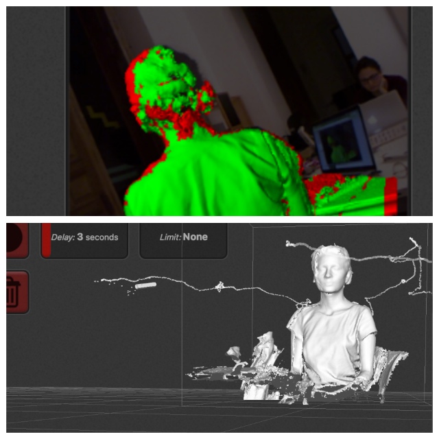
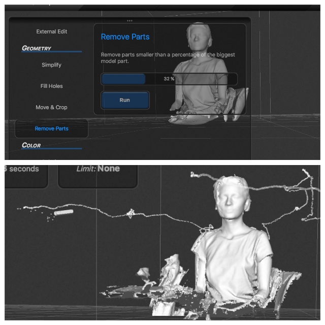
3. Removing parts like kinect wire or desk
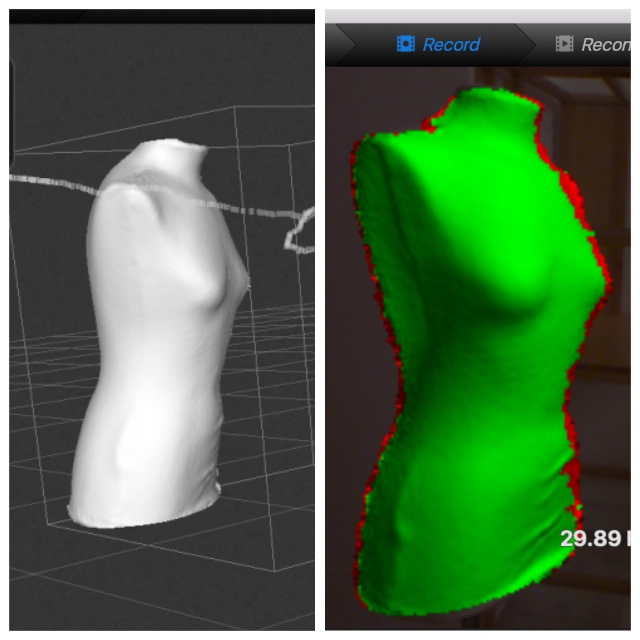
4. Finally i made an object scanner too :
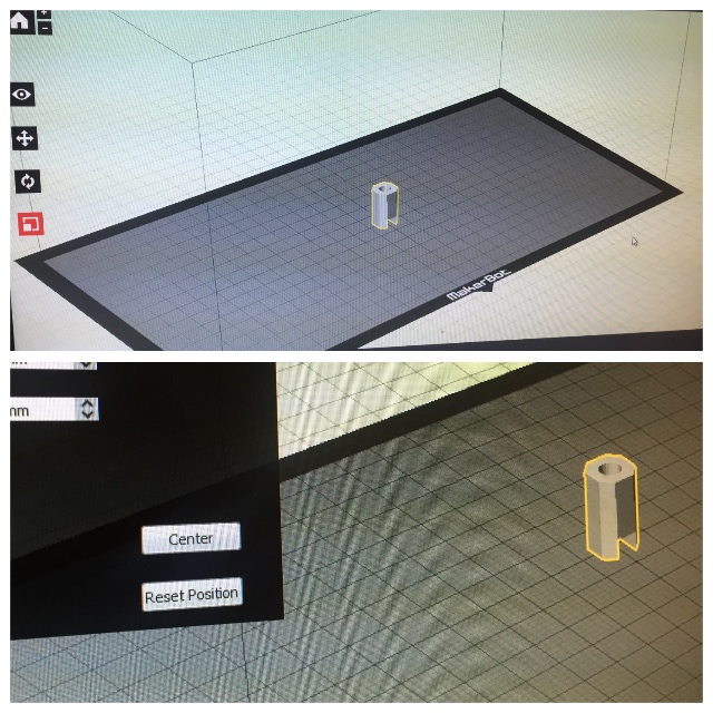
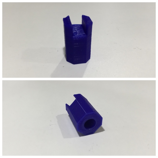
At my "Final Project Production Planning", this assignment was great for practice the design and print about parts of my Kite. I was designing with OpenScad some possible "Ends Caps" with differents diameters considering the "Carbon Tubes" at market´s available :
| Material | Profile | Temperature | Speed | Support | Raft |
|---|---|---|---|---|---|
| Thermocromic Filament by Chamaleon Filaments | 210º | 80 | No | Yes |
WEEK FILES
During this week we had some problems as group. The communication between us was a failure. This cause that we had to repeat a lot of things but the experiences was fantastic for learn the knowledges commented.
After our conclusions with the group practices i can to say that now i have new tips about Tolerances, Angles and Bridges that probably without this certificate i will learned spending more time.
WEEK CONCLUSIONS