Week 09
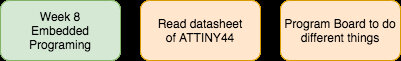
Embedded Programming
Group assignment
- compare the performance and development workflows for other architectures
Individual assignment
- Read a microcontroller data sheet. Program your board to do something, with as many different programming languages and programming environments as possible.
Learning outcomes:
- Identify relevant information in a microcontroller data sheet.
- Implement programming protocols.
Have you:
- Documented what you learned from reading a microcontroller datasheet.
- What questions do you have? What would you like to learn more about?
- Programmed your board
- Described the programming process/es you used
- Included your code
Week workflow
Tools used
- soldering station
- usbtiny ISP
Software Used
- AVRdude
- Arduino IDE
Introduction
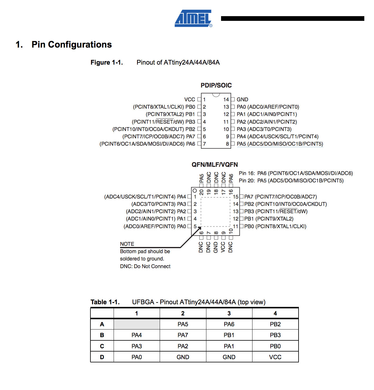
Read the Datasheet
A few thoughts about it:
- are you joking? 200 plus pages of very technical stuff!
- slept on the first pages
- is there a movie version?
One a more serious note, I really think this assignment is one of the hardest I m stuck because of this datasheet.
Will jump to programing and use it to consult only. While I do will detach important sections bellow:
Programing
Because I was a bit confuse on how to do it I decided to list all steps in detail and have some sort of template for my next projects. With what is applicable I fill the gaps after each step and do while documenting it, and that is what follows bellow:
- Burn bootloader
- identify programer
- identify bootloader and makefile
- download bootloader
- identify commands to burn bootloader
- burn bootloader
- Burn firmware
- identify example code:
- identify commands to compile and burn firmware
- compile source code
- Adapting makefile to work with my programer
- burn firmware
- identify what fuses to burn
- burn fuses
- avrdude or Atmel Studio 7 (windows only)
- for that I start by pointing I want to program a ATTINY44A
- Download makefile
- Bootloader is not going to be used here since there is no USB
- not applicable
- nope
- nope
- There is this code from Prof. Neil
- with all files prior downloaded on one directory, in linux I rename the file to makefile and run the script to create the firmware (this step I will repeat every time I want to modify the code:
mv hello.ftdi.44.echo.c.make makefile
make
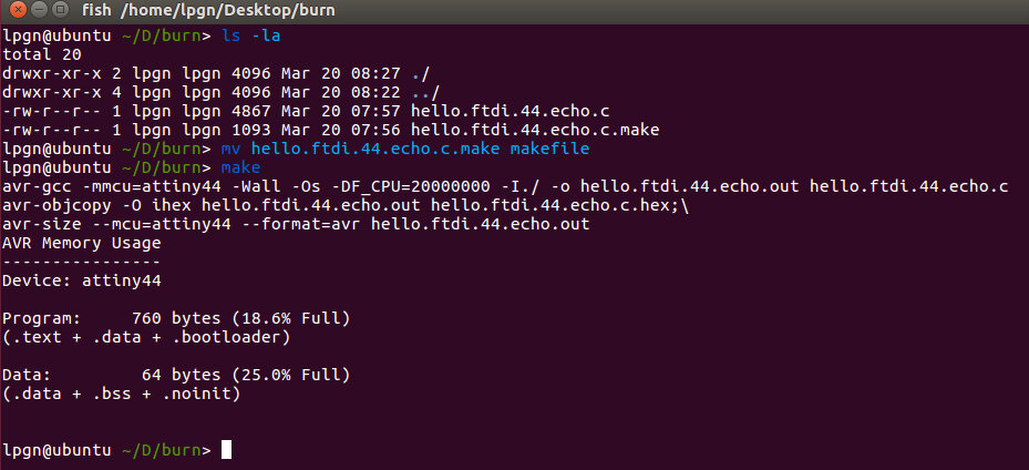
- done in previous step
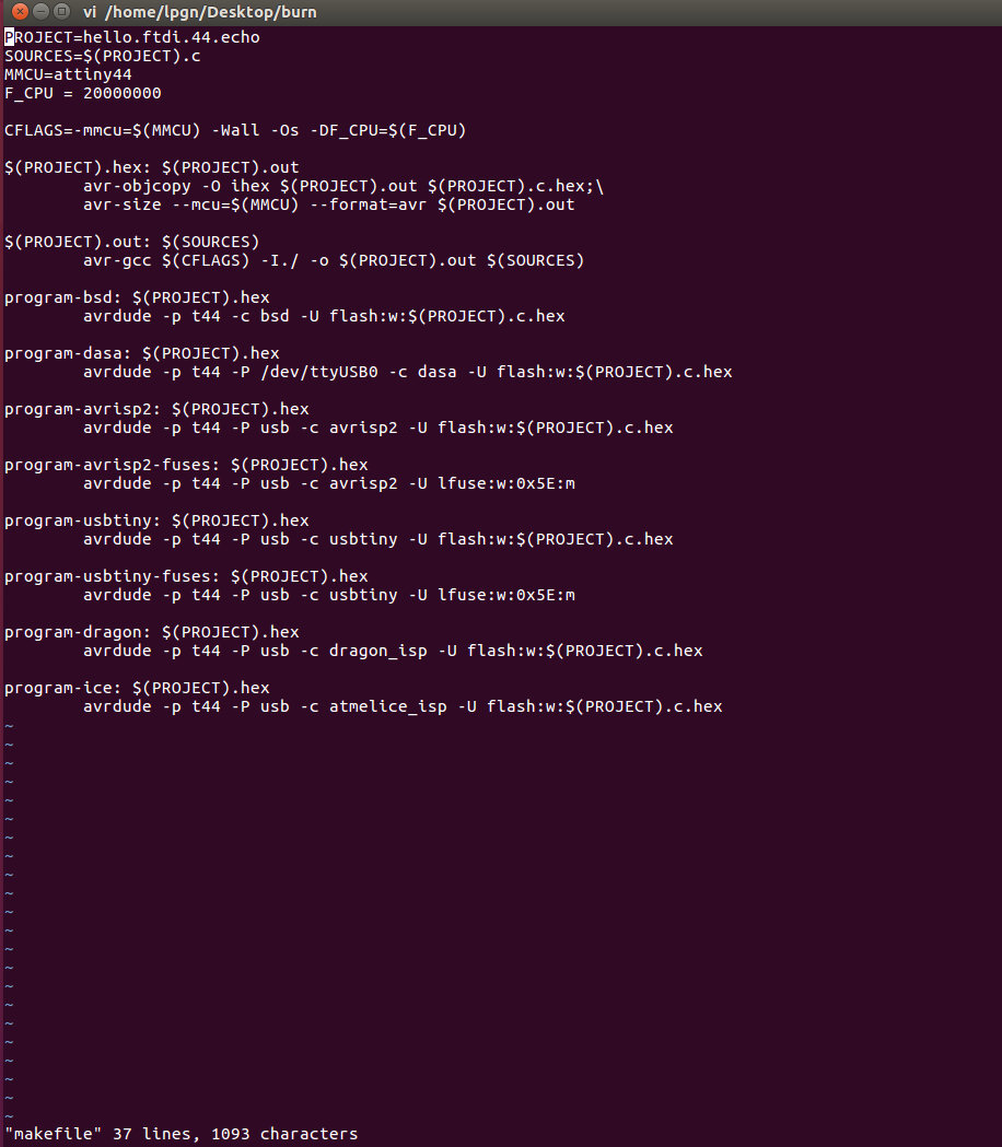
run:
make program-usbtiny
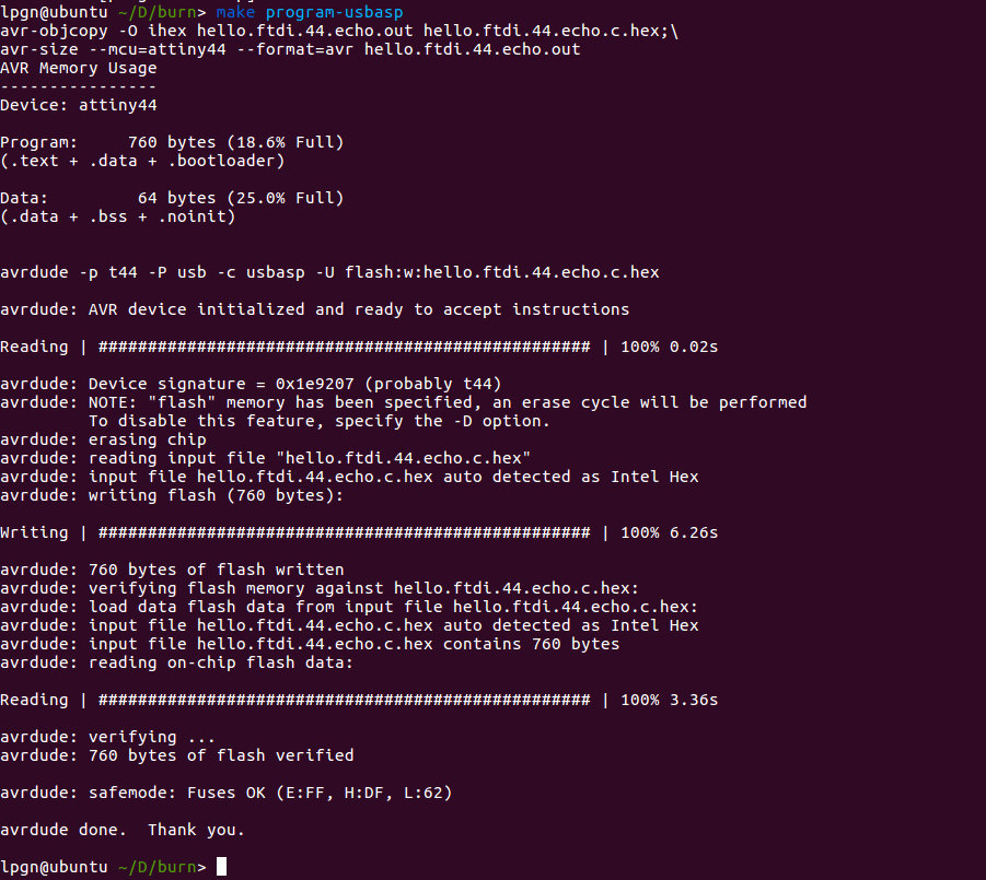
- that was done already in the makefile
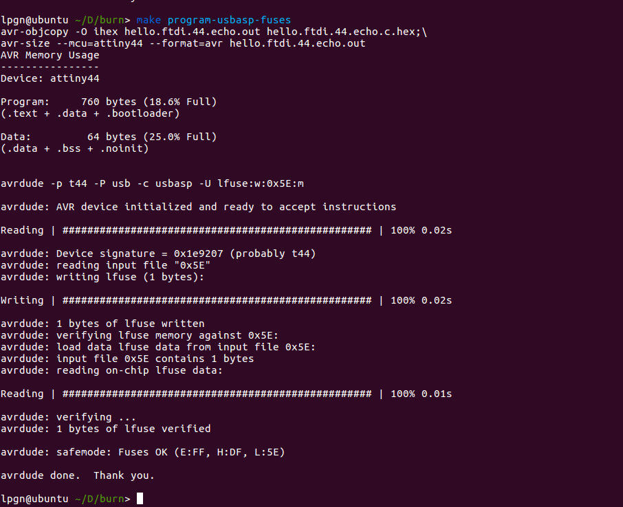
run:
make program-usbasp-fuses
Programing with Arduino IDE
I decided to try Arduino IDE as well to program my board.
In order to do it there are a few steps that should work regardless of the os
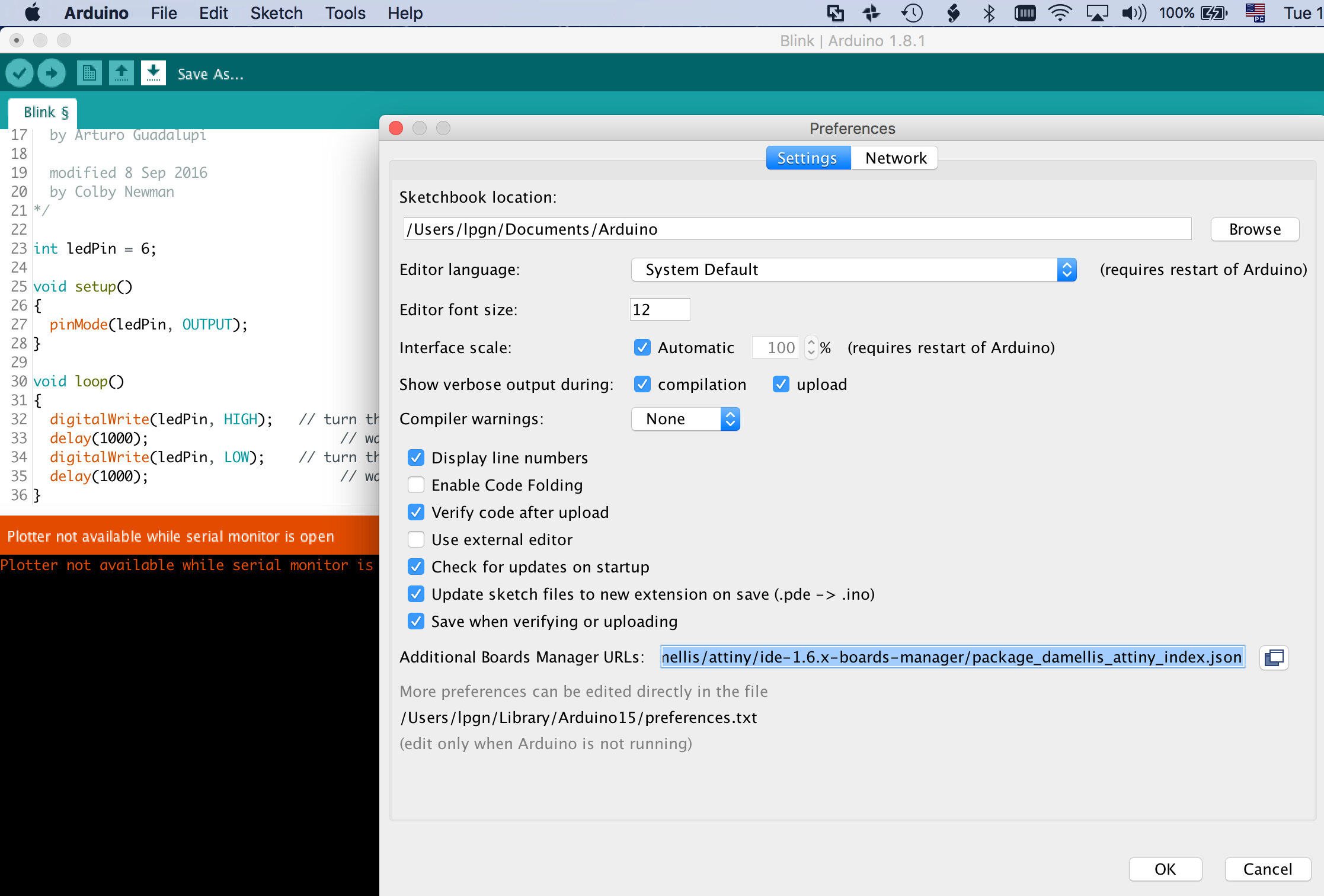
- Add additional board to the boards manager:
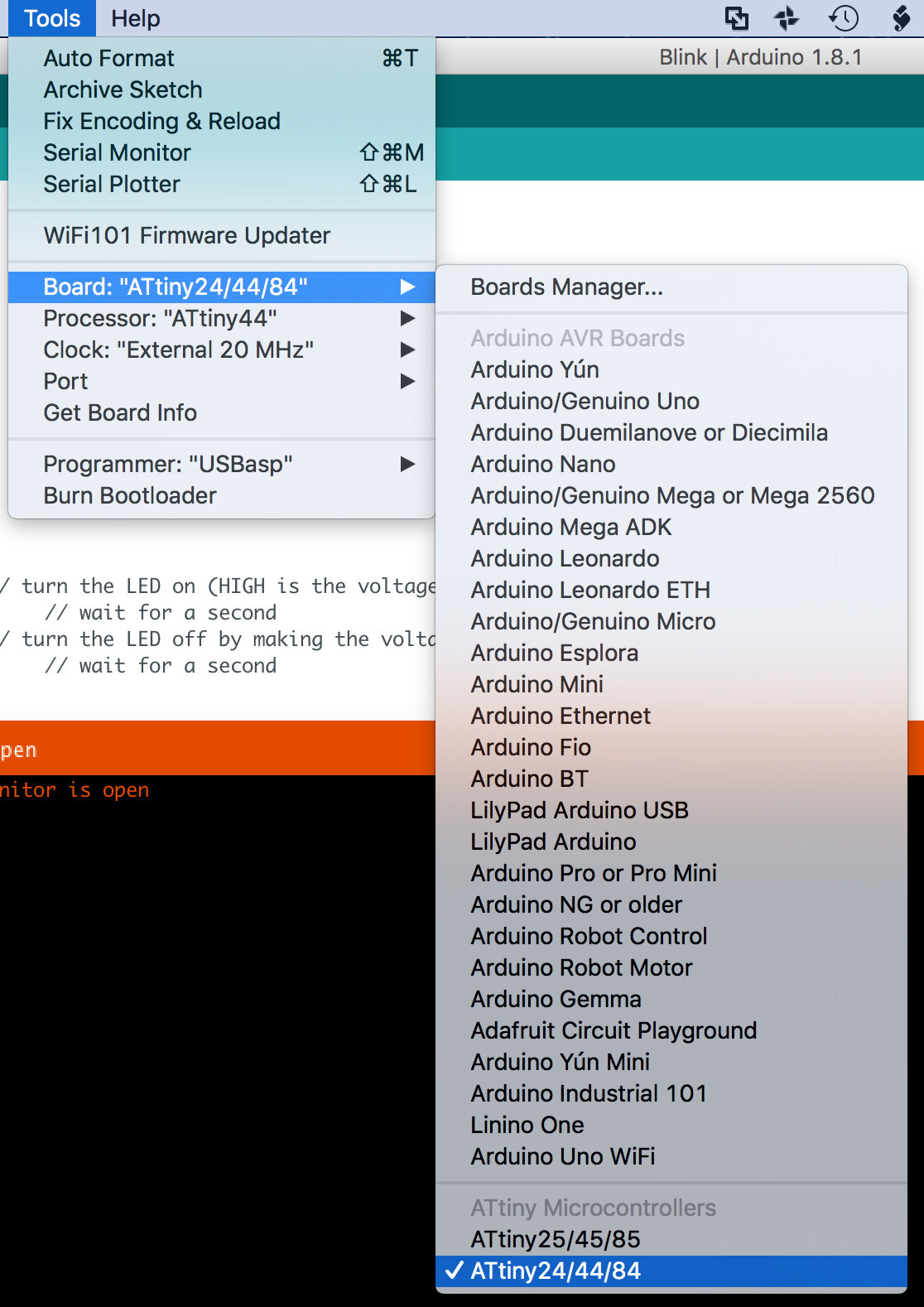
- Chose your new added board, in my case ATtiny44
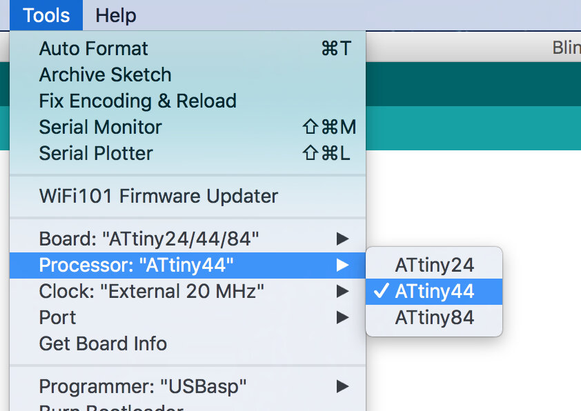
- Chose your processor, same as before
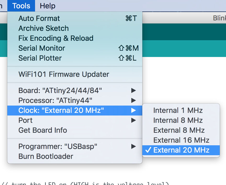
- select clock, because I am using an external 20Mhz oscillator, I chose "External 20 MHZ"
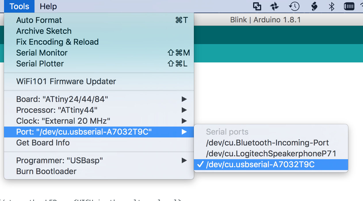
- Because I want to do some serial monitoring on this board I chose the best mach for my FTDI wich is "/dev/cu.usbserial-A7032T9C
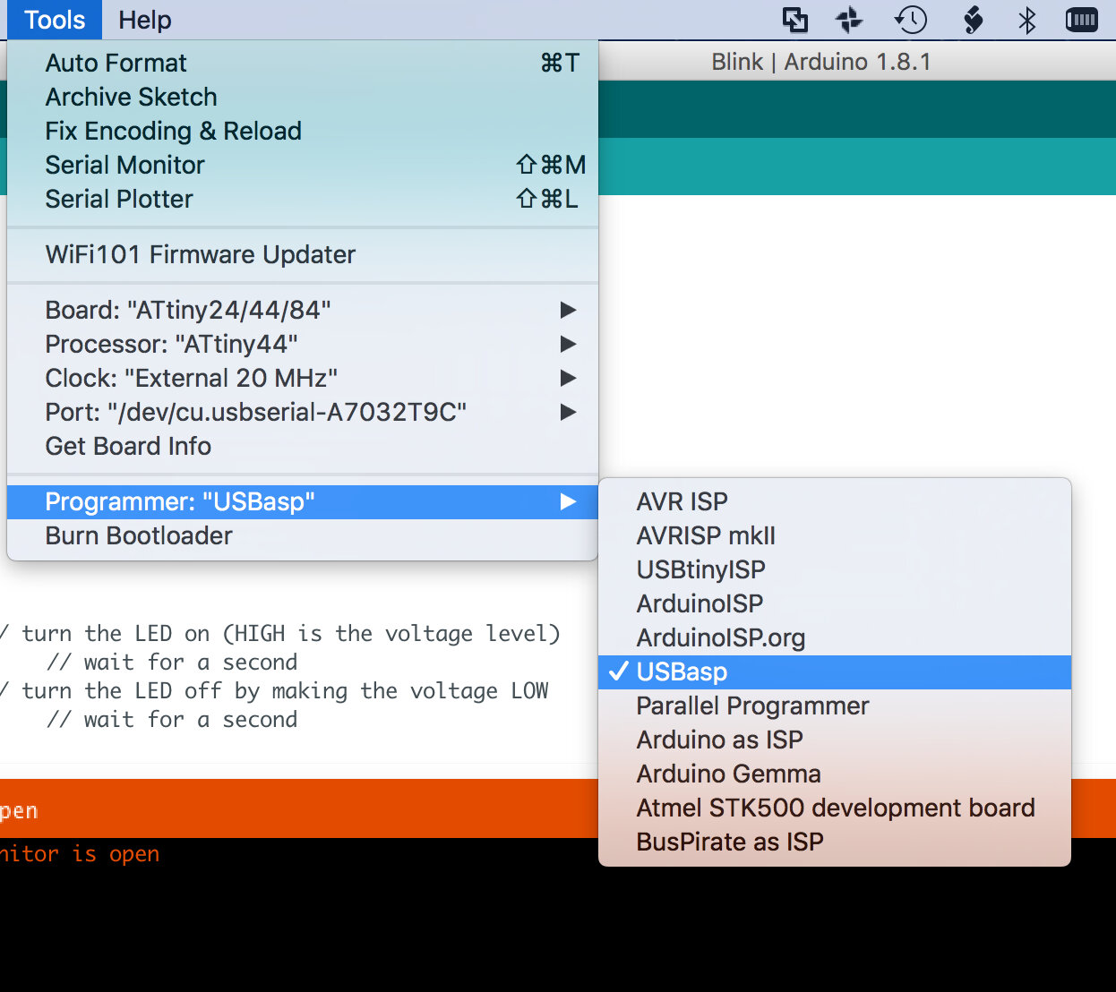
- The last step before compiling and burning was to select the programmer, in my case "USBasp"
Paste the following into (Preferences)-(Additional Boards Manage URLs:)
https://raw.githubusercontent.com/damellis/attiny/ide-1.6.x-boards-manager/package_damellis_attiny_index.json
First test
Burning Neil's code "hello.ftdi.44.echo.c"
Here instead of using terminal and avrdude, I used the Arduino IDE as it has a built-in serial monitor.
The results are as follows in the video
Program something else
Now I will try to program it to blink as I press the button.
- determine the pin where switch is connected
- determine the pin where LED is connected
- Code
- wait for button
- if button pressed blink LED 3 times
- if not go back to begining
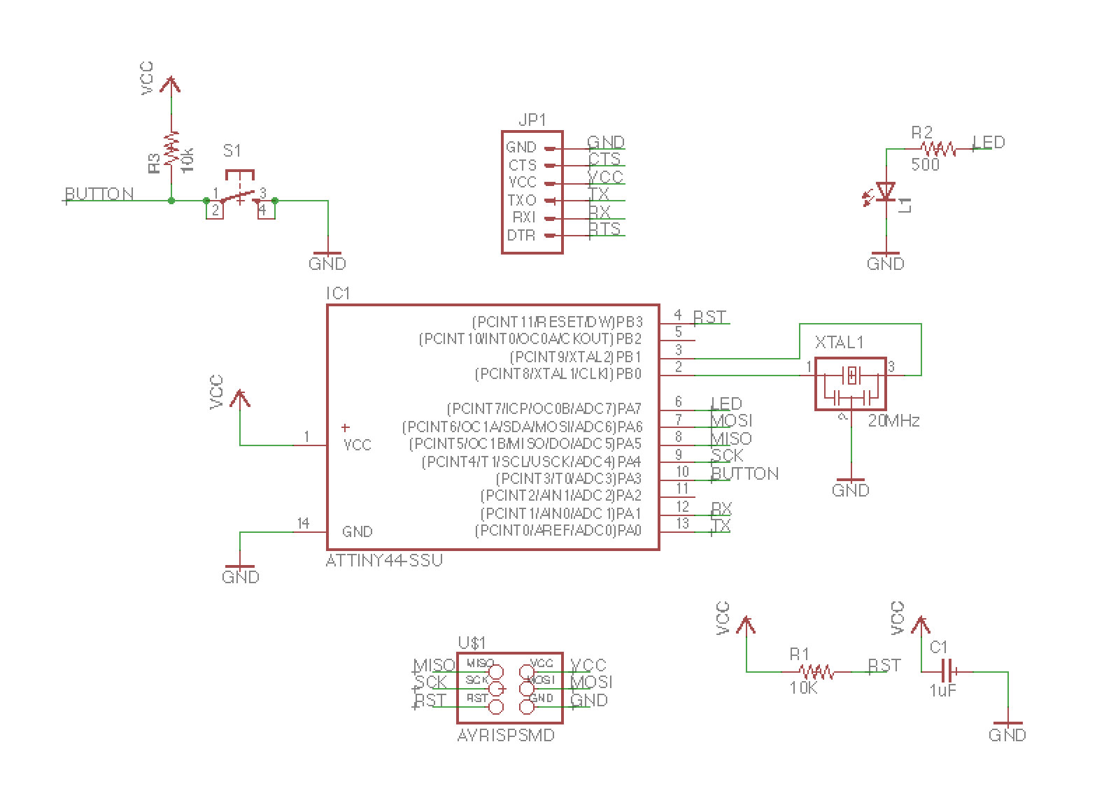
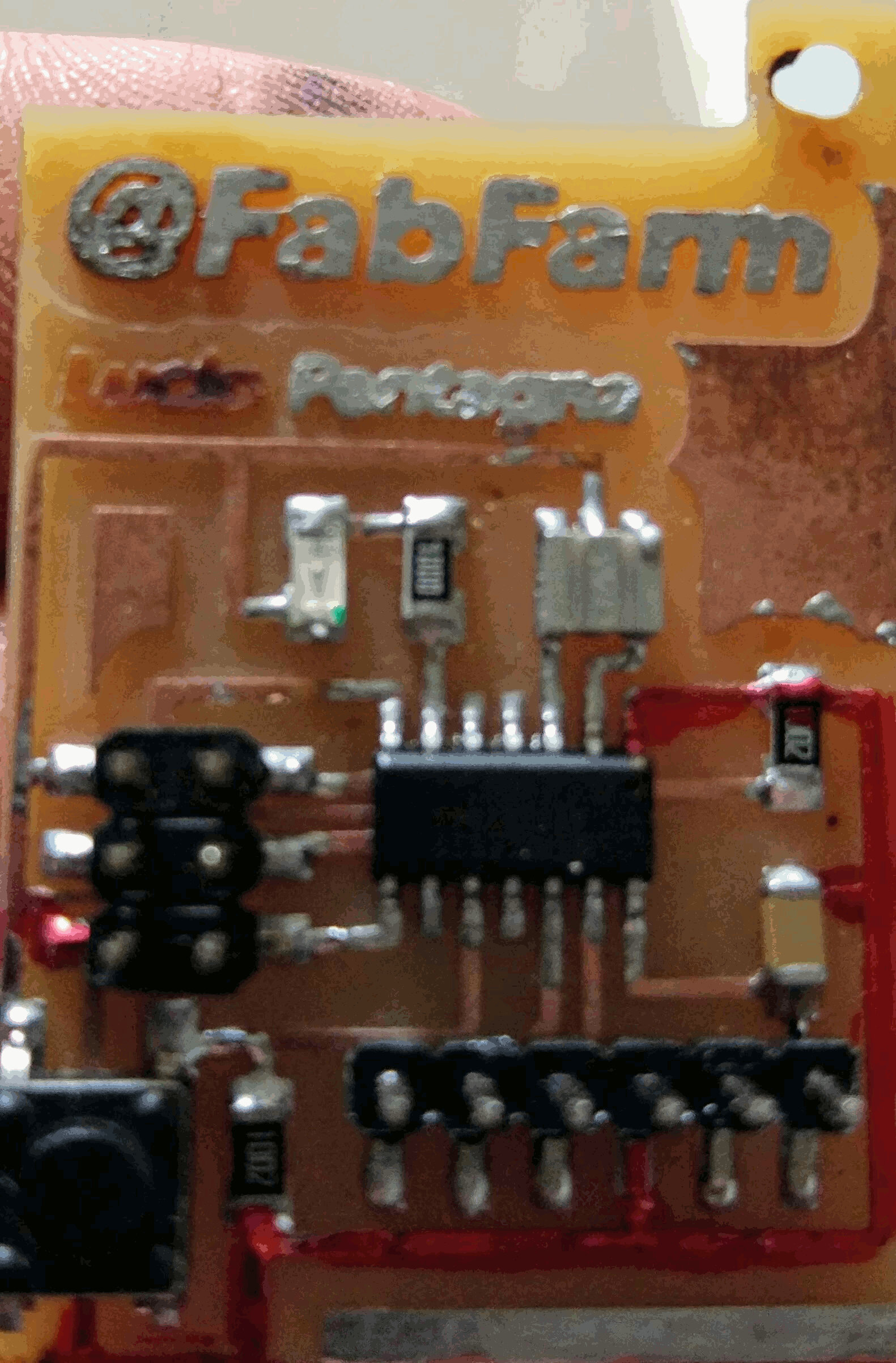
after looking into the PCB schematics I determined the button is connected to pin 10
after looking into the PCB schematics I determined the LED is connected to pin 6
In human language I want something like this:
the problem is I never really coded from scratch only changed code, so that will be a challenge...
1st iteration
how did I do it
I Tried first to customise the blink code from Arduino IDE with my pin numbers, That did not work
I realise after trial and error that the pin number on the data sheet does not correspond to the arduino pin number.
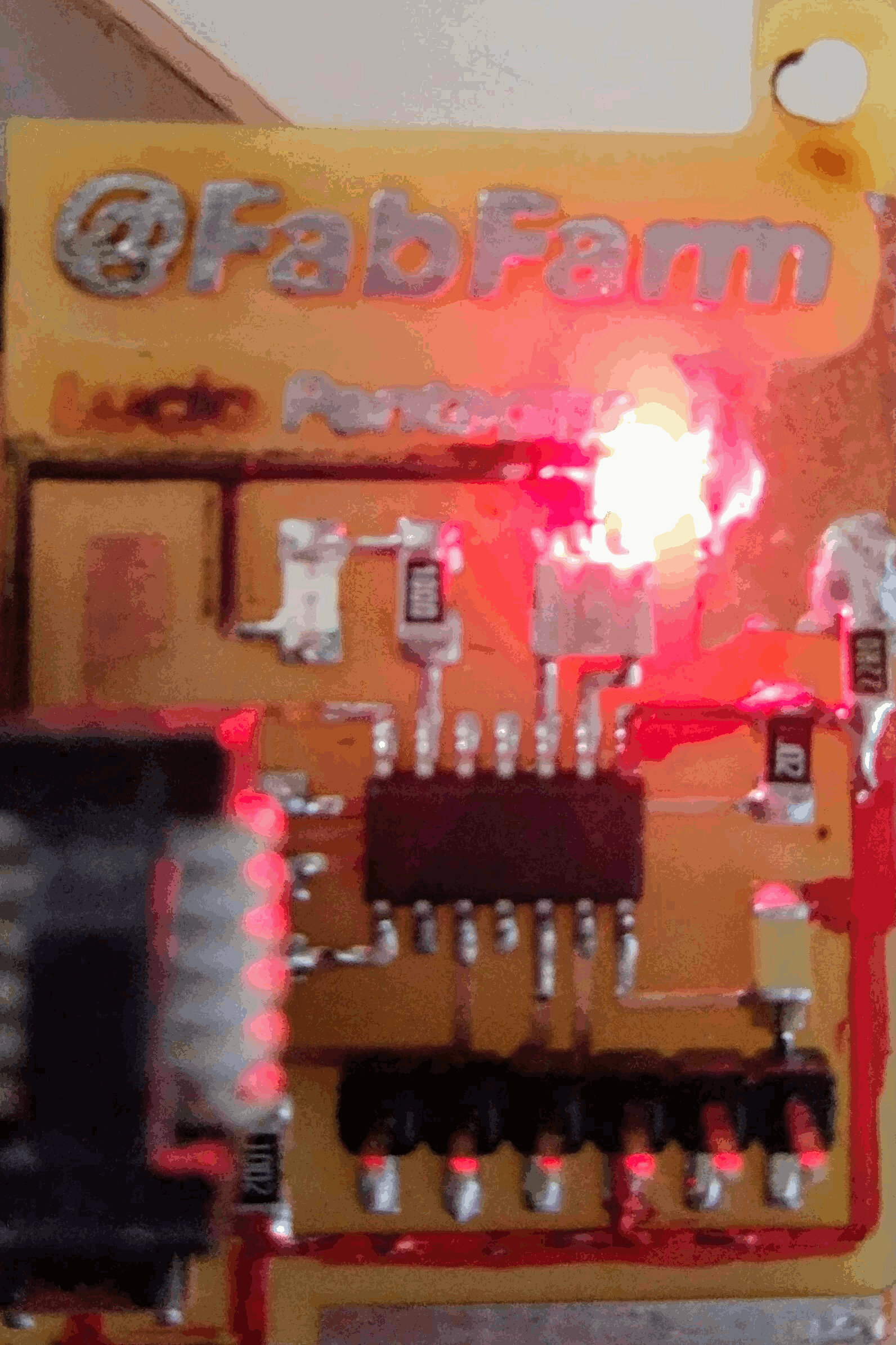
So after empirically finding the right pin number I programmed the board and got it to blink!
Next I wanted the LED to react when pressing the button, so I searched for attiny44 arduino pin. With the right pin number in hand I replaced the pins in the code and it worked!
now I inverted when the LED turns on and off.
Side activity
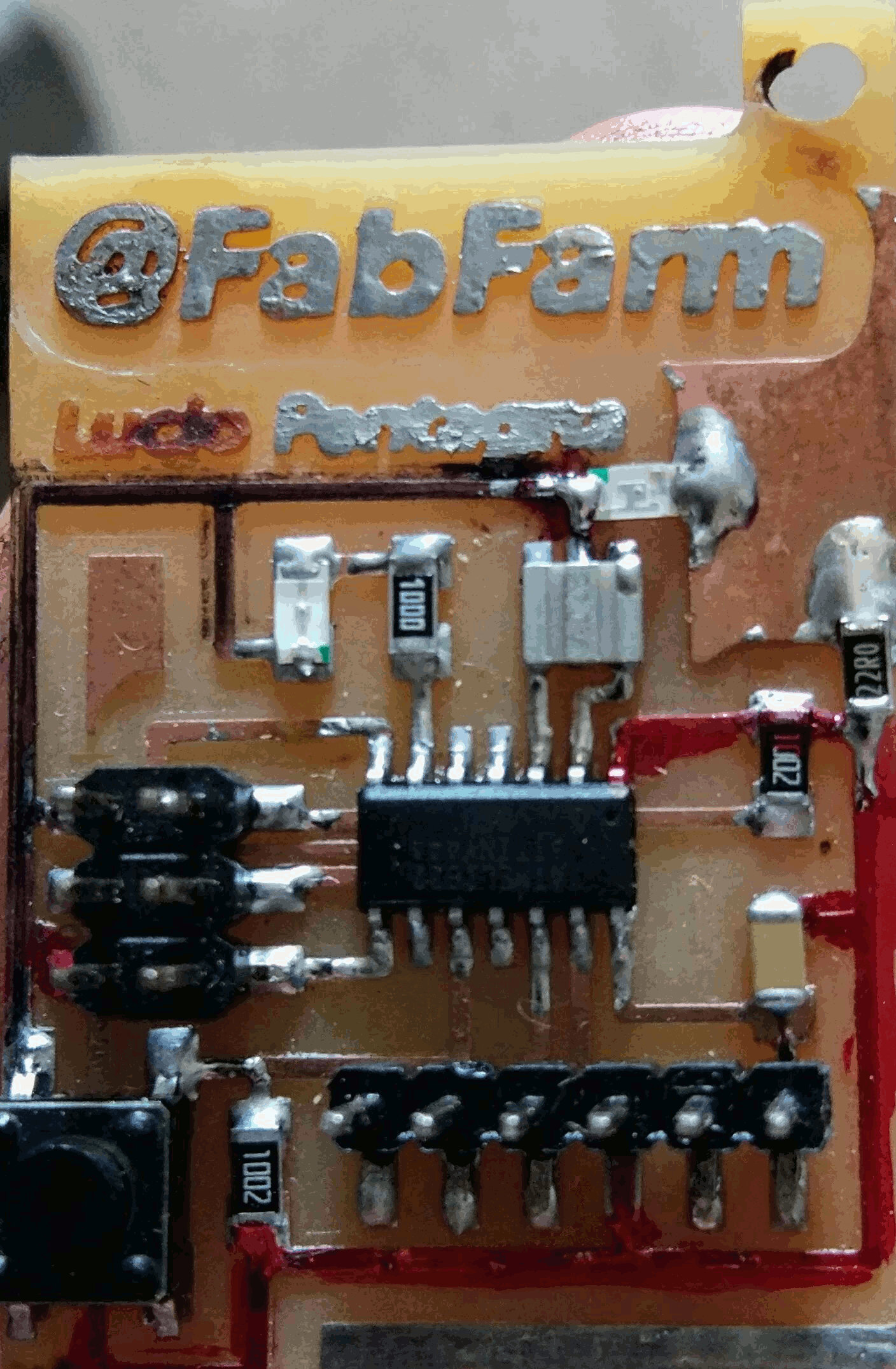
I was a bit annoyed my board would not advise me when powered so I decide to solder a red LED and a 22 Ohms resistor and a resistor so if I got the connections wrong I would know and switch it.
Thats the before and after