
Index
GROUP PROJECTS : ELECTRONICS PRODUCTION
PCB Production process
GROUP TASK
Characterize your PCB production processes for your machine
The cnc
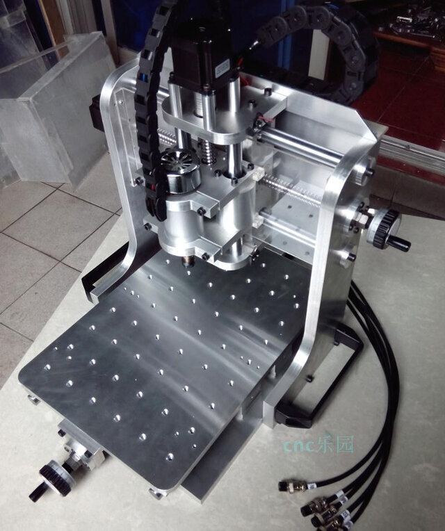
Specifications
Caracterisation
Milling
For the milling process we will use the following software:
- Fab Modules
- Mach3
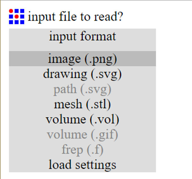
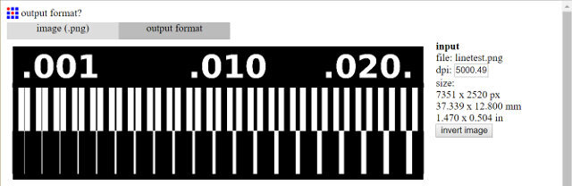
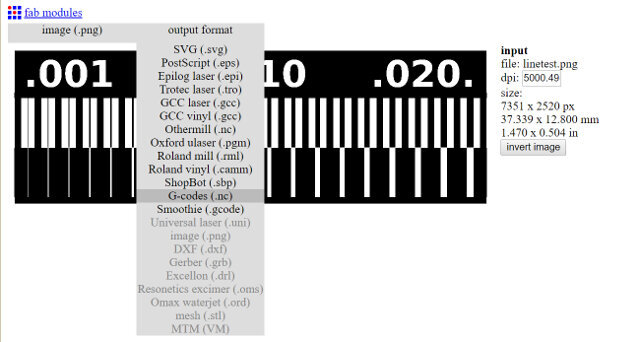
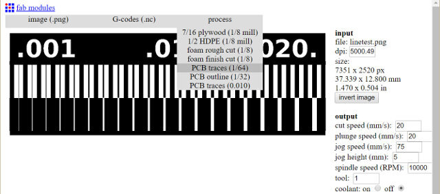
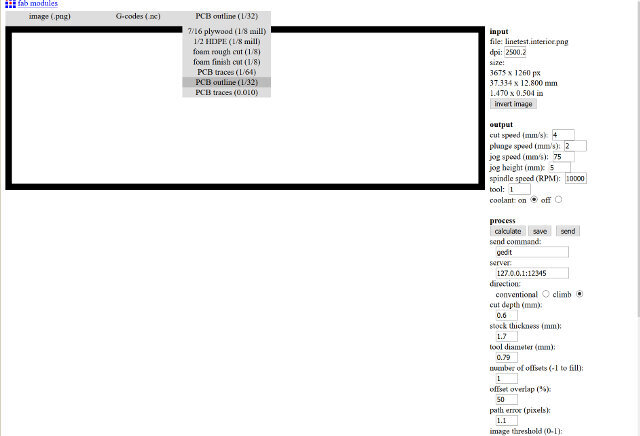
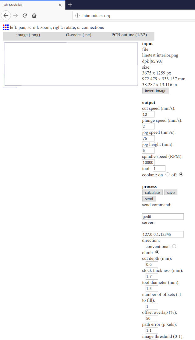
Fab Modules
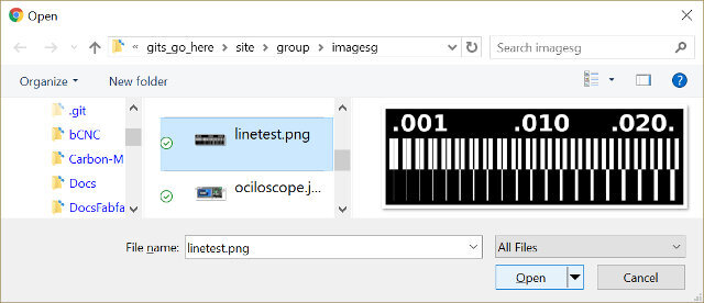
We start by downloading a hi-res pattern at the electronics production site.

At Fab Modules


FABRICATION
Here are the two gcodes
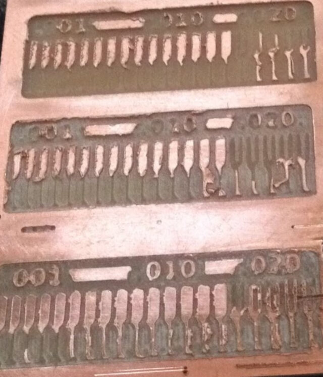
The preliminar results milling
After milling the test patterns we notice that the results were very bad
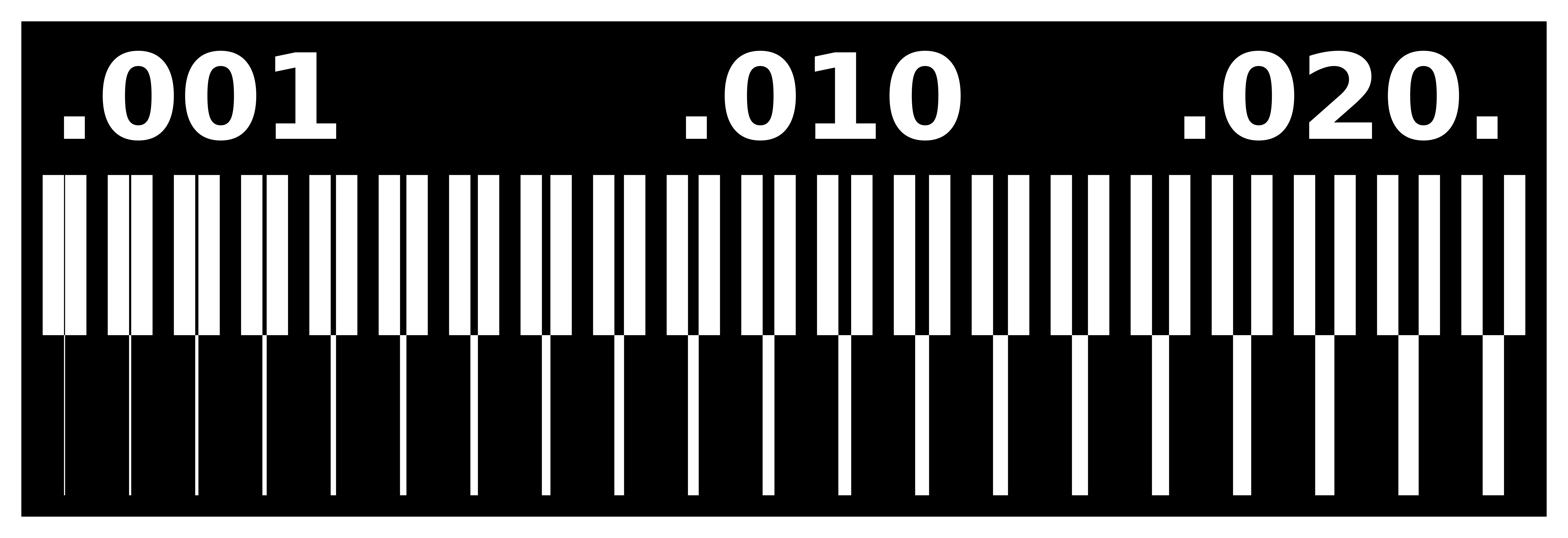
After a close inspection of the cnc spindle we came to the conclusion that the cnc had its spindle's shaft bent and due to that the cuts were not smoth. In the following photo you can see the instrument used to measure the variation.
We disassembled the spindle and took it to a machinist. After a few days we returned with the spindle but the problem continued. So our solution was to hammer side of the shaft with the highest variation with a metal mallet
Success we fixed the spindle's Shaft and no more variation as seen on these recording:
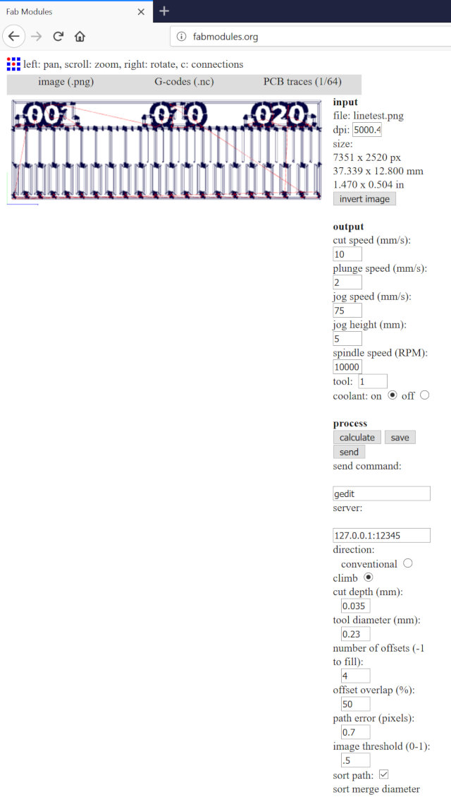
Doing it over
Now with the shaft fixed and a new bit we made the folowing test.
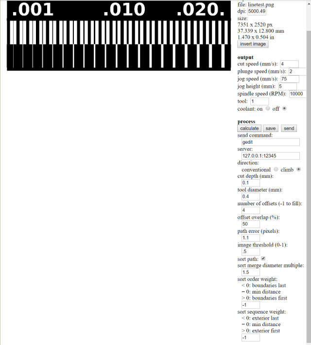
Main setings:
- cut speed (mm/s): 10
- cut depth (mm): 0.035mm
- tool diameter (mm): 0.23
- path error (pixels): 0.7
- cut speed (mm/s): 10
- cut depth (mm): 1.7
- tool diameter (mm): 1.5
- path error (pixels): 0.7
The final result
We milled again the template and the traces are better defined. I am not totally happy with the results as I used the only mill bit suitable for the job at the lab. And thats still not so good. This mill bit is not straigth it is angled with 30 degrees. So if the piece is not totally flat some parts will be getting a bigger with than the other.
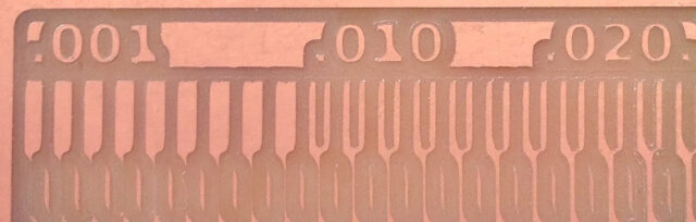
Conclusion
On a examination of the cutted template we can assume our settings are ideal for the current mill bit. Its crucial to have a flat bed. Also the lab is aquiring new mill bits that should improve the results even more.
Selected settings:
- cut speed (mm/s): 10
- cut depth (mm): 0.035mm
- tool diameter (mm): 0.23
- path error (pixels): 0.7
- cut speed (mm/s): 10
- cut depth (mm): 1.7
- tool diameter (mm): 1.5
- path error (pixels): 0.7
