
GROUP TASK I
Measure ANALOG levels AND DIGITALS signals from input devices.
The INPUTs Measurements :
1st Exercise :
For begin with the week, we decide to use the sensor attached to the board designed by Pilu at Networking and Communications week assignment focussed in her final project.
So for understand better this input device you can visit all the design and fabrication processes here :

STEPS FOLLOWED
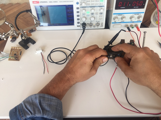
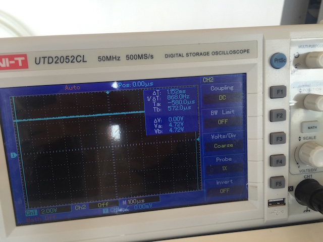
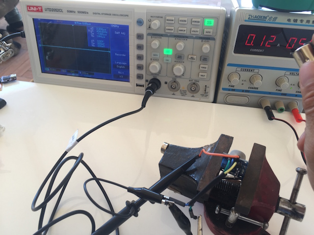
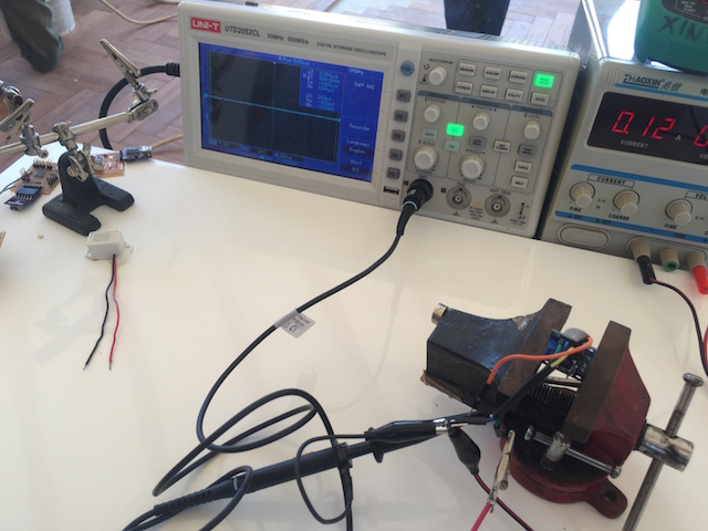
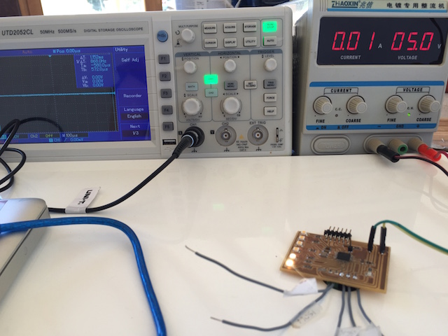
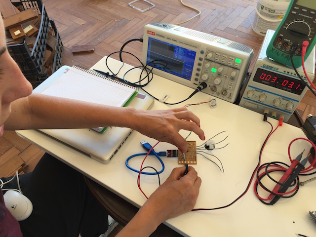
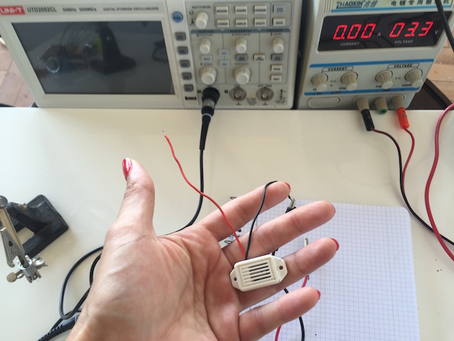
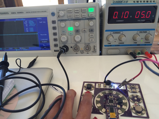
1. Lucio attached the sensor to the Oscilloscope and powered it with the regulated power supply to 5volts :
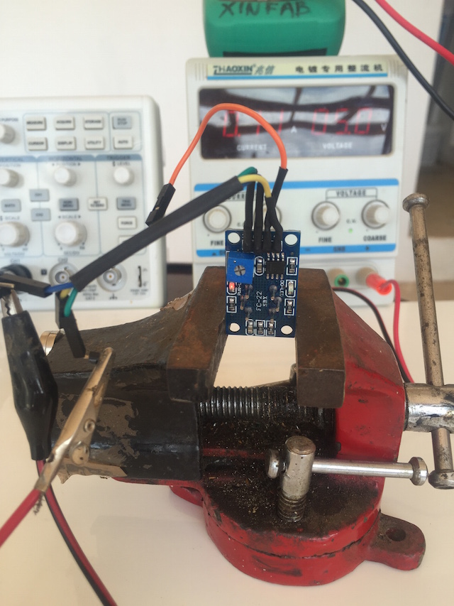
2. When we connected it to the power supply we also observed the current used when the sensor is using his analog functions:
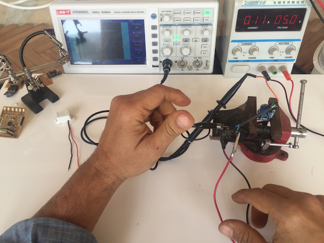
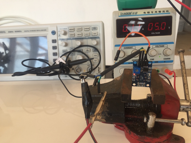
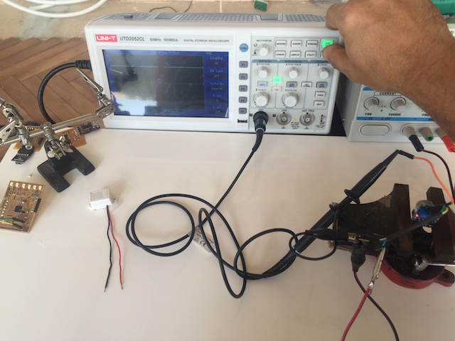
3.When all the the wires was attached, lucio pressed the Auto Set function at the oscilloscope and we observe different things :
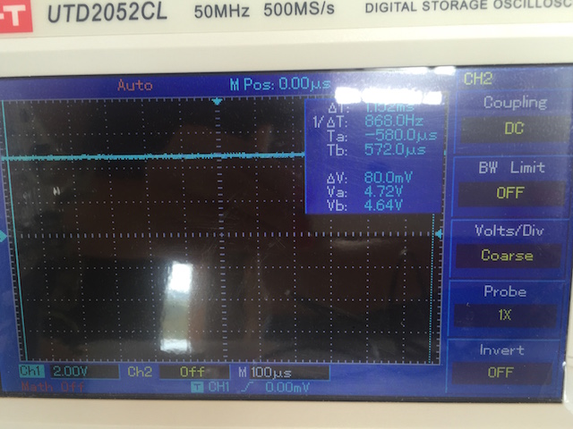
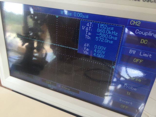
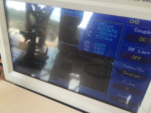
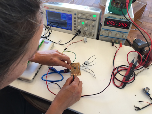
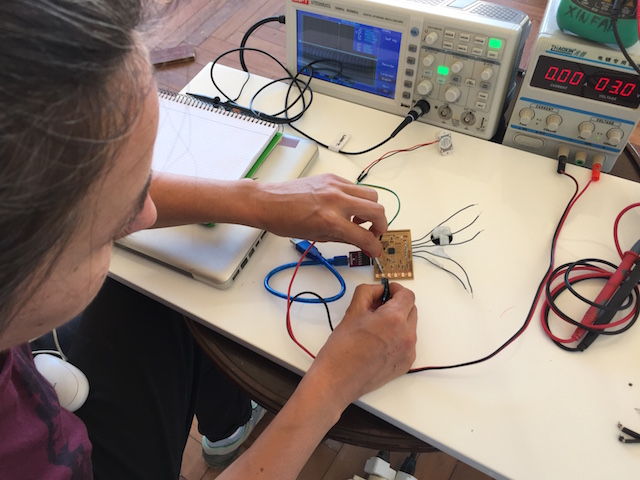
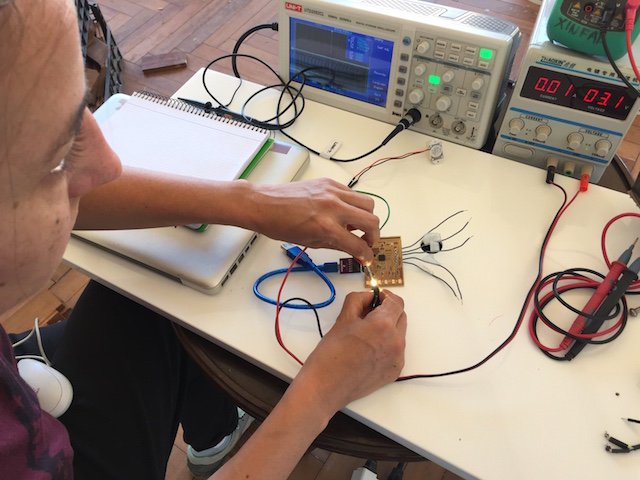
4. After observe analog levels when the sensor is working in clean and pure area, we decided to use a lighter with the idea to observe how the sensor detect the gases from it.
CONCLUSIONS
2nd Exercise :
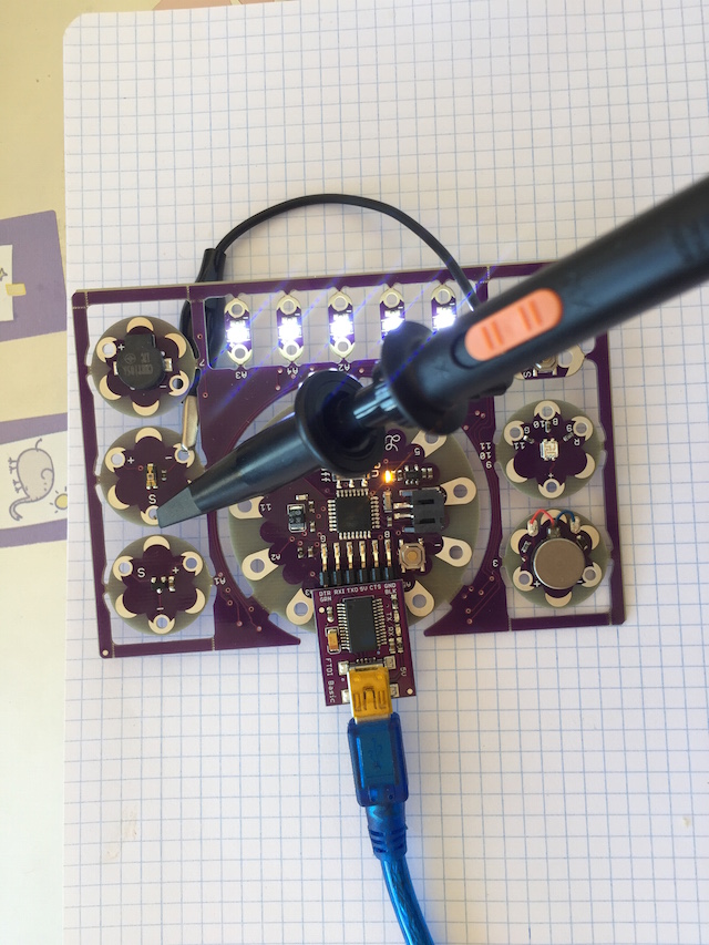
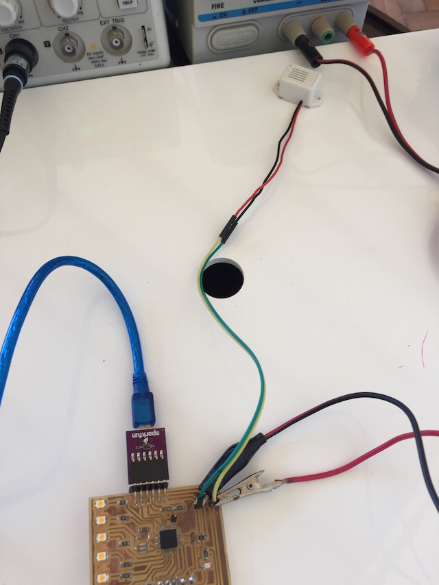
Later pilu decided with the idea to measure possibble INPUTS DEVICES for her final project, to use a commercial board designed by Leah Buckhley at the MIT where she teach about Open Textiles since 2010.
Pilu use a lot this board for introduce quick to her students to soft circuits and embbded programming.
She wrote a code for use the LDR (Light Dependent Resistor) sensor acording to the white leds attached too and measure the analog levels with the oscilloscope:
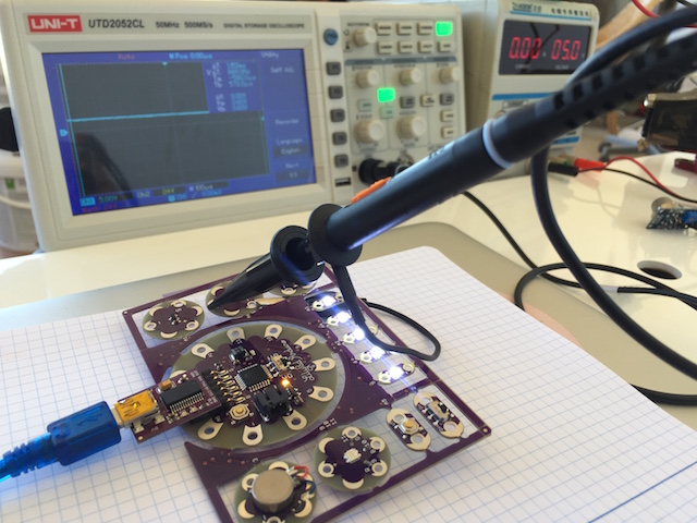
You can see at the next video how the signals present some noise at the waves drawed by the oscilloscope after Pilu to press the autoSet.
GROUP TASK II
During the Output Devices week we must to do some practices in group about them with the idea to learn about the Power Consumption of any Output Devices.
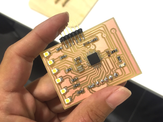
The Output: This is the output device which we want to use for make this practice :
1st Exercise :
As we mentioned above, for this part of the assignment we decided to use the output device designed by Pilu during the weekly assignment, so if you want to know more about her design and fabrication processes check her page linked below.
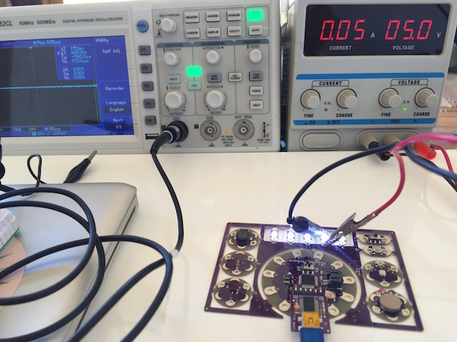
As you can see at the pic, the board have bright leds that my old instructor bought to China and he never gave me the datasheet so this practice is a good oportunnity for learn about the consumption of them.
STEPS FOLLOWED
This was the steps that we followed :
1. We switched on the regulated power supply and regulated it to 5V for observe the total consumption.
2. Later, we regulated the power supply for don´t burn the leds to 3V and observed the amperes used when the leds are HIGH or LOW:
3. Finally for calculated the Power Consumption of every led we applied the following formula :
3 x 0.001 = 0.003 W -------- 0.003x 60 = 0,18 Wh
3 x 0.003 = 0.009 W -------- 0.009x 60 = 0,54 Wh
2nd Exercise :
This exercise consist in calculate the power consumption of the Piezo used on the board so we followed the same steps described above:
1. For begin, we regulated the power supply to 3 Volts because the output works from 1.5 to 3 volts.
2. So we attached the positive pin to +, and the negative to - :

3. So for calculated the Power Consumption we applied the same formula : V x A = W .
3 x 0.001 = 0.003 W -------- 0.003x 60 = 0.18 Wh
3 x 0.003 = 0.009 W -------- 0.009x 60 = 0.54 Wh
2nd Exercise :
So following the formula practiced before :
5 x 0.05 = 0.25W -------- 0.25x 60 = 15 Wh
5 x 0.10 = 0.50 W -------- 0.50x 60 = 30 Wh
CONCLUSIONS
INDIVIDUALS ASSIGNMENTS WEEK PAGES
If you want to visit our own pages for know more about our design and fabrications for this week check below :
