Wildcard!

Week 17

Introduction

Introduction

We recently installed an indexer for our shopbot, which allows for 4 axis milling. My assignment for this week is to expand our knowledge of how to use it and to discover some of the options it offers.

Testing and preparing Individual project

Only mildly wild

Getting to know the indexer

Carl's wildcard week

My wildcard week is closely linked to Carl's, since we figured out how to zero the various axes together, found the proper paths and tools and did a bunch of the troubleshooting together. While Carl created the first test piece for the machine and used an old bit (just in case anything went wrong), I added the spiral pattern and used a proper bit to see the difference that this would make.

Carl also set up the machine before I joined him, so he desrves most of the credit for that part.


Lots of air

On our first few attempts the machine was milling nothing but air, but doing it with great enthusiasm. Eventually, we found the small piece of information, which states that "size of cylinder" is what the machines is estimating from. While we were z-zeroing our machine meticulously to the side of the rectangle, the machine thought we were z-zeroing the cylinder, which was about half the size of the rectangle. This meant that the machine never reached the material.

To deal with this, we changed the toolpath and settings to z-zero from the center. We then zeroed as before, then moved the head clear of the material and lowered it by half the width of the material to reach the actual Z-zero. Once we set this as our new zero, we could maneuver the head back into position and start the job, this time to good effect.


Nice cylinder, then more air

I set my v-carve toolpath, which went very fast, due to everything we learned from Carl's project. I then added the spiral path, which is a gadget that draws the correct lines, which you then use with the 2D profile path to gain the desired effect. I saved them together and milled the paths.

Of course, once the cylinder had been cut and it was time for the spiral, the shopbot happily resumed cutting the air to pieces. I had forgotten to set the spiral to the correct diameter. After fixing the path, I decided to test whether I could now set the z-zero on top of the cylinder, which worked just fine, now that the piece I was working with was an actual cylinder.

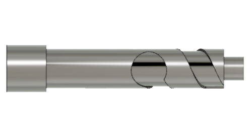
Once I made a new toolpath with the correct size, it came out really well.


How to almost not make anything

Here you can see the indexer creating a beautiful spiral pattern for me, then the material bends upwards and nearly snaps at which point the video goes nuts because I am hitting the emergency stop. Note to those attempting this: Use thicker material, secure it really well and be ready with that stop button.


Fusion 360 to indexer in one smooth workflow

A closer look at what the indexer has to offer

The test project

I drew a cylindrical design with a tab at the top for slotting into the base of the Wisp, and a design of a wisp flying down the pole. I decided to keep it as simple as possible, since this is the first time I try this.


The Patch work space

I had never looked twice at the Patch environment until today. Essentially, it's a part of Fusion 360 which allows you to create bodies with 0 thickness. A sort of "skin". This environment is used to prepare your model for 4th axis CAM. It can also be used to modify your model, as it offers a different set of tools particularly well suited for wrapping features around a cylinder.

Because I wanted to give reliable information, I had already tried the process with the large part of the cylinder before I began this part of the documentation, but I will take you through how I do the small tab at the top, since it is exactly the same process.

First of all, by clicking "Create - Offset" I created an offset body, but set it offset at 0mm, meaning it is just the surface of the features I selected.

Awesome intro to 4th axis CAM Part two of awesome intro to 4th axis CAM

Splitting your 0mm body

Because of the way the 4th axis CAM works in Fusion, we need to create a closed area instead of the cylinder. Otherwise, Fusion won't know how to wrap the toolpath, and will return errors. This is why we select "Modify - Split Body". We use the XZ plane as our tool, because it intersects our cylinder. We can also draw a new plane if none of the existing planes intersect the cylinder, but in this case, we do not have to.


Extending edges

We only need one of the halves we just created, but the program will become buggy if you delete the other, so just hide it, and focus on the one we need. Select an edge of the cylinder, then go to "Modify - Extend". You specify a distance to extend the edge. In our case, we want it to go as close as possible, which for me meant extending it by 35mm or so.


New Setup

Our indexer revolves around the y axis, so when I selected "Setup - New Setup" I was particularly careful to align my stock with that axis. The stock I have is a 60mm thick cylindrical pole. So I altered the stock to those values. I also set the origin point to be at the bottom of my design, just so I know how to zero my axes when the time comes.


2D Adaptive Clear

Only a few of the available drilling paths function with 4th axis milling. The one I used most was the "2D - Adaptive Clearing" option.


Wrapping the 2D path around the cylinder

First, select the tool you intend to use. In my case, it is a 6mm upcut milling bit with 3 flutes. Then go to "geometry". The first thing you click MUST be "wrap" box. Select the cylinder you are wrapping your path around. Then select the pocket you will be milling, in our case, this would be the "rectangle" we created in the patch environment. Then go to "passes" and tick the box that says "both ways" This will make the milling time shorter. Then further down, in "Radial stock to leave" type in " - (half the radius of your tool). In my case, I used -2.5, since I wanted to be on the lower side. This will make the path cross over the small space left between the edges of our "rectangle", thus giving us a fully milled pocket.

Now click OK, and watch the path be calculated. I first generated the large path, then the small tab, as the second goes further in than the first, and therefore will not need to mill through all the material that the first pass just milled away.


2D Contour

I wanted to add a bit more detail to my design, so I used the coil tool to create a spiral pattern, then added a small circular shape to represent my wisp. I once again used the patch environment to create 0mm bodies of these features, which I combined into one feature for the sake of convenience. I then returned to the CAM environment. where I followed the same steps as above, except this time I selected 2D - Contour at the start. Once again, select your tool, then click "wrap" before clicking anything else. Then select the path you want the path to follow. This time, we are not milling a whole pocket, but just a contour, as the name of the path suggests.


Simulation

To check if all my paths work as intended, I watched the simulation of how the path will work. Of course, on the indexer, the tool will only be moving on the x, y and z axes, while the stock will rotate around the y axis, but the simulation still gives a good approximation of what the job will look like.


Adjusting Settings

While the milling bits for wax and electronics are relatively well organized, the bits for our Shopbot are unlabelled in a box. It makes it difficult to categorize the tools. The one I chose is a 1/4", 4 flute, upcut, flat end mill. It appears to be coated with some sort of protective layer. I have no information about serial number, manufacturer or other info beyond what I can deduce by inspecting the milling bit itself.

I estimated the chip load and calculated the speed and feed rates using a calculator. I chose the standard surface speed for this sort of wood on the same page. I added this tool to my available tools for the job, then updated my toolpaths to use the new tool.

Feeds and Speeds

Post Processing

Now, because I plan to use the same milling bit for the entire project, I made sure that my paths were in the correct order. I then right clicked on my setup and clicked "post process". There, I selected the Shopbot OpenSBP post config, and I changed "4th axis" to "yes" and changed "B rotates around x" to "no" since our B rotates around Y. I clicked "post" and the path came out great. If I would have forgotten to select the 4th axis or to untick "B rotates around X", the path would have returned an error.


Zeroing

I had to change my stock to a square beam I got from the local wood-shop. It was too short, so I added a second piece to the front and secured them as well as possible, hoping for the best. I zeroed my x axis to the middle of my beam, and the y axis to the point on the beam where I want my job to start. I zeroed z by getting Bergþóra to help me so we could use the Z-zeroing tool. I then moved the tool clear of the beam and went to -37 (half the thickness of the beam). This way, the Home point is in the middle of my beam, just like it is in my setup. This was something we learned by working with V-Carve before.

Of course, I had to go into the setup and change the stock in the CAM as well, so that it would know what material to remove.


A broken bit!

Normally, when we run jobs on the shopbot, it will tell us when to turn on the spindle. This code did not do that! Instead, it just started the job and before I could hit stop it went straight into the stock and broke the bit! Be very careful of this. Check your code to make sure that it turns the spindle on before moving anywhere.

I will from now on always check a new and uncertain path by zeroing the z axis in the air above the piece and doing a test run. Breaking things feels bad.


The devil in the details

On closer inspection, I found some issues with the post.

  • "SA" means that it sets the tool to absolute distances as opposed to relative distances. This is good. We want this. "CN, 90" calls up the My_Variables file to set user variables from a predefined list.
  • "IF %(25)=0 THEN GOTO UNIT_ERROR" Seems to be a safety protocol of some sort.
  • "(ampersand)PWMaterial = 75" Indicates how thick the material is, which is correct.
  • "(ampersand)PWZorigin = Part Surface" - This is a big culprit. I was certain that I set my z-origin to be the center of the material.
  • "2D Adaptive9" This is the name of the first path from Fusion.
  • "JZ, 39.5" It starts by telling the path to jog to Z position 39.5. This is about 2mm off the surface of the material, so it should be just barely safe enough.
  • "JH" This tells the tool to Jog Home to the X and Y positions. This means that the tool moves above the part.
  • "J5, , , , , 178.629" As far as I can tell, this spins the part on the B axis, although I am not sure why J4 is not used, since this is not a 5-axis job. If my tool was hovering, just 2mm off the surface of the job, and then the square stock is rotated, this would most certainly have caused the breakage of the tool!
  • "C7" This command means Spindle OFF! The correct code to turn the spindle on is "C6" at least on our machine.
  • "(ampersand)Tool = 2" This prompts the user on whether Tool 2 is in the holder.
  • "TR, 9931" This is the designated spindle speed
  • "C6" Here, finally, the spindle is turned on. After this point, the code looks normal, seemingly telling the machine where to go.

Possible solutions

The first and easiest thing to attempt to fix, is to simply zero the z-axis on top of my part, and hope that this adjusts the cut. Worst case scenario, it will be doing an aircut, which sounds like a pretty good idea right about now. The most likely result is that this way, the spindle will be prompted to be turned on while the tool is still at a safe distance, at which point it can begin the job proper.

If that does not work, my next option is to find out why the job wants to zero from the surface of my part. If it does so reliably, that is great... as long as you know, and don't expect it to behave like a v-carve toolpath.


Origin point

To be absolutely certain of my origin point, I went back into my setup on the Fusion CAM workspace. I right clicked my setup and selected edit. In Origin, I selected "Stock box point" Meaning that I will select a specific point on the stock box to use as Zero. I then selected the middle of my stock material on the x axis, the top of the material for the z axis, and the base of the stock material for the y axis. This means that when I zero my axis this time, I will need to zero them in those same places for the job to work as intended.

To update my toolpaths, I select each one in turn and press "Ctrl-G". It takes a few seconds to recalculate, but then I can post process the paths the same way as before.


B is skipping

Okay, so fixing the path, the origin point, and now it should go smoo... Oh. I ran the job in the air to see if it would behave, and as soon as it began turning B, it skipped, sounded strange, and quickly announced that there is a parameter error. I checked on x, y and z, and they're all fine, which indicates that B is the limit. Most likely caused by my jerry-rigged setup with two pieces of wood. Now I will loosen the two bolts holding the tailstock, move it closer to the material and fasten it again. According to Carl, this will be fine.


Adjusting stock is not enough

With the stock adjusted, I checked again, and received the same error. (Parameter value blow range for VS -- Setting to Lower Limit .253999...) Checking the internet, this is sometimes a problem. Apparently, this is usually cause by placing an inches per seconds value in an inches per minute box. As in, the computer things that it should move 0.25 inches per minute as opposed to 0.25 inches per second.

I checked my tool settings, which are all at inches/minute. However, when I consulted my calculator again, I noticed that there is something called "XY feed rate". I am going on with the assumption that this corresponds to the "cutting feedrate in Fusion 360. This was set to 39, but ought to be at 438. Considering what the forums say about this type of issue, and that every formula I can find agrees with the "XY feedrate", I am updating these values and trying again. In the air.


Air cut with no errors

The new tool settings seem to have done the trick. The air cut resulted in no errors or issues, but it did move slowly and oddly jerkily, possibly just because the steps are small. My second attempt, after restarting the machine was no more satisfying and I became worried that it might damage the machine, so I shut it down. The milling bit was spinning just fine, but wasn't moving the way my simulation showed that it ought to.


New setup, comparing code

Figuring that something may be wrong with my setup, I created a new one. For this one, I zeroed my z axis in the middle of the stock. Comparing the code actually became very interesting, and I started noticing odd things about my first code. While both the pocket and the adaptive toolpaths for my new setup were working as expected; x is stationary, z only moves rarely and incrementally, while y and b do most of the real work, the 1st path I generated is completely different. x fluctuates by mm each step, and so do all the other coordinates! This reflects the jittery mess I tried running before.

The z values for the 1st path fluctuate from -15 to 104, which is a range of a whopping 130. That's almost twice the thickness of my stock. That makes no sense. Meanwhile the new pocket path starts at z 67.326 and steadily becomes lower until it ends at z 25. Perhaps more importantly for comparison, my new adaptive clearing path also starts at z 67.326 and steadily becomes lower until it, too, reaches 25. This indicates a serious problem with my initial setup compared to the new one. In fact, ending at 25 corresponds to the thickness I intend for my cylinder, which will have a radius of 25mm.

I never knew how to read g-code until I had to. Now it all seems much more understandable.


Clearance and multiple passes

Since my stock is 74mm square, pythagoras tells me that at it's widest, the radius will be 52.3 mm. This means that the new adaptive clearing toopath will begin cutting , if not immediately, then relatively quickly into the process. I have therefore chosen to use the new adaptive clearing toolpath, although I discovered one more issue. The very first part of the path is to jog to Z 39 (2mm above the stock surface), then Jog home for X and Y(still okay), then rotate B by 179(SNAP!). This would break my tool, just like it did on my first attempt, because the corners stick out to 52.3 mm, meaning that the very minimum safe height for that initial z move would be 56, though I would prefer 67, which is 30mm off the surface.

The easiest fix is probably to just edit that first JZ value manually, changing it to 67 or so. Due to time constraints, this is what I chose to do. If anyone else finds a better fix for this issue, I would be happy to hear about it.


Editing the code

The easiest fix is probably to just edit that first JZ value manually, changing it to 67 or so. Due to time constraints, this is what I chose to do. If anyone else finds a better fix for this issue, I would be happy to hear about it.

To quote the OpenSBP Shopbot programming handbook: "The files that ShopBot reads are in what is called 'text' format. That means you can look at them and edit them with any text editor or word-processor" So I chose to open my sbp file in notepad, and change the initial JZ value to 67. The code will now start at 67, then approach the material where it will start a circular plunge until it reaches Z 49.326 at which point it will start milling the adaptive clearance pattern. This is ideal, as it is exactly 3mm deeper than pythagoras says our corners will be.

Later, I found the fix in Fusion. There is a safe retract value in post which was set to 2mm. I changed this to 15 and got satisfactory results.

Programming manual for Shopbot OpenSBP

Zeroing Z: top or center?

I am just as impatient to see the final product as you guys must be by now, if you've read all this, but there is one more thing we have to do first. Since the v-carve model wanted us to center at the middle of our stock, and the Fusion path hasn't been the most predictable, I will first run the code in the air above my part. I will then zero with the Zzero plate on top of my material and run the code again. If that does not work, I will zero to the center of the material using fancy math (minusing the Zzero plate coordinates by the half the thickness of my box) and run the code one final time. By doing it incrementally like this, I am taking the least possible risk with our machine, the tool and my material.

As it turns out (get it, turns?) the z axis needed to be zeroed in the middle. However, the job is still running very slowly. As if the feedrate isn't doing what it is meant to. It is as if the units are wrong, but I can't see what it is that needs fixing.


Data starving?

Data starving occurs when the control becomes so overwhelmed with data that it cannot keep up. CNC controls can only process a finite number of lines of code (blocks) per second. That can be as few as 40 blocks/second on older machines and 1,000 blocks/second or more on a newer machine like the Haas Automation control. Short line moves and high feedrates can force the processing rate beyond what the control can handle. When that happens, the machine must pause after each move and wait for the next servo command from the control.

This sounds like exactly my problem. My toolpath has 167k lines in it, meant to be executed in only 13 minutes.Some fast math tells me that this means that my CNC would have to read a whopping 214 lines per second. Our decade old Apha PRS probably can't keep up with that.


Ramping values

Eventually, I turned to Bas, our guru, the wise. He told me to look up ramping and I got learned good.

Ramping is when the machine "ramps" the speed as it approaches a turn. This is meant to reduce jerky moves and produce smoother finishes. However, when your code consists entirely of constantly changing, short movements, the machine will be in one ramp action when it enters the next and the next after that, essentially becoming stuck in a perpetual series of very short, jerky, slow moves. This is why my job was moving so oddly.

According to the guide below, I most likely need to adjust my MDC value to make the ramping algorithm perform more things without adjusting the feedrate.

Guide on setting ramp values in Shopbot 3.

conclusion

The indexer is really exciting, and I can't wait to try doing more complex jobs with it. It is a little bit fiddly, but once you get to know it, it behaves as well as your shopbot, which in our case means it has the same gremlins, but at least they're familiar.

Next page Fab Academy