In this assignment we contruct an In-System-Programmer (ISP). It is used on other lessons and on the final project to program the electronic devices that control machines or automate other tasks. The steps to construct this device are:
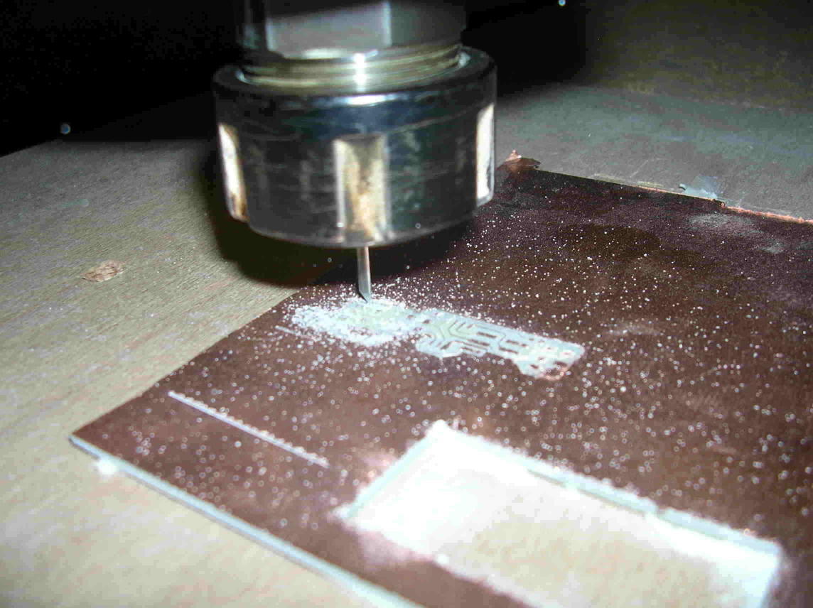
Electronic circuit board fabrication is done by one of two methods. The chemical method is the most contaminant. The cutting method contaminates less because it does not use poisonous chemicals. We used the cutting method. A milling bit cuts the copper mask at the places that should not conduct electricity leaving copper conductive paths which replace wires.
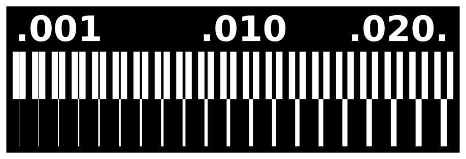
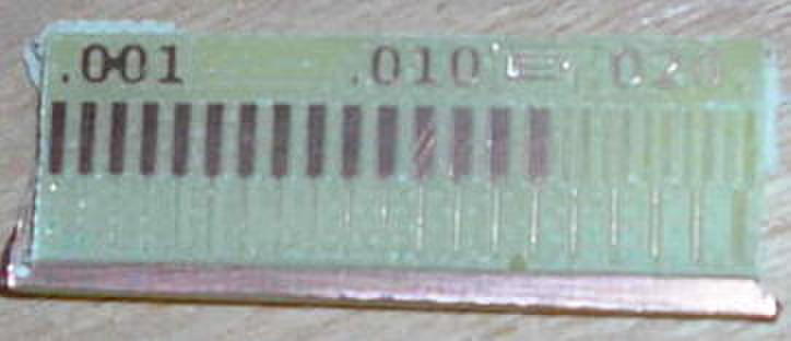
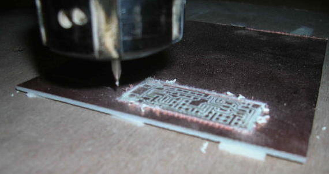
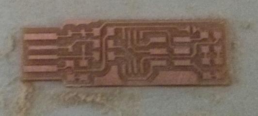
A test board is milled with the different distances for checking which is to be used for the final boards.
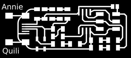
The source files from Neil's site

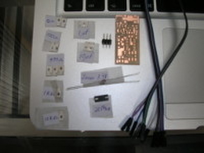
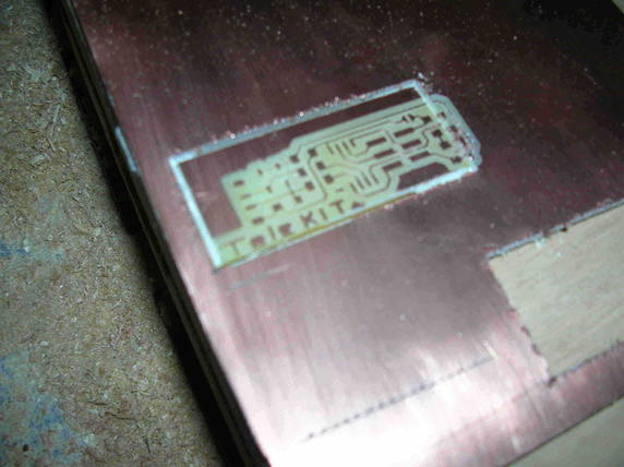
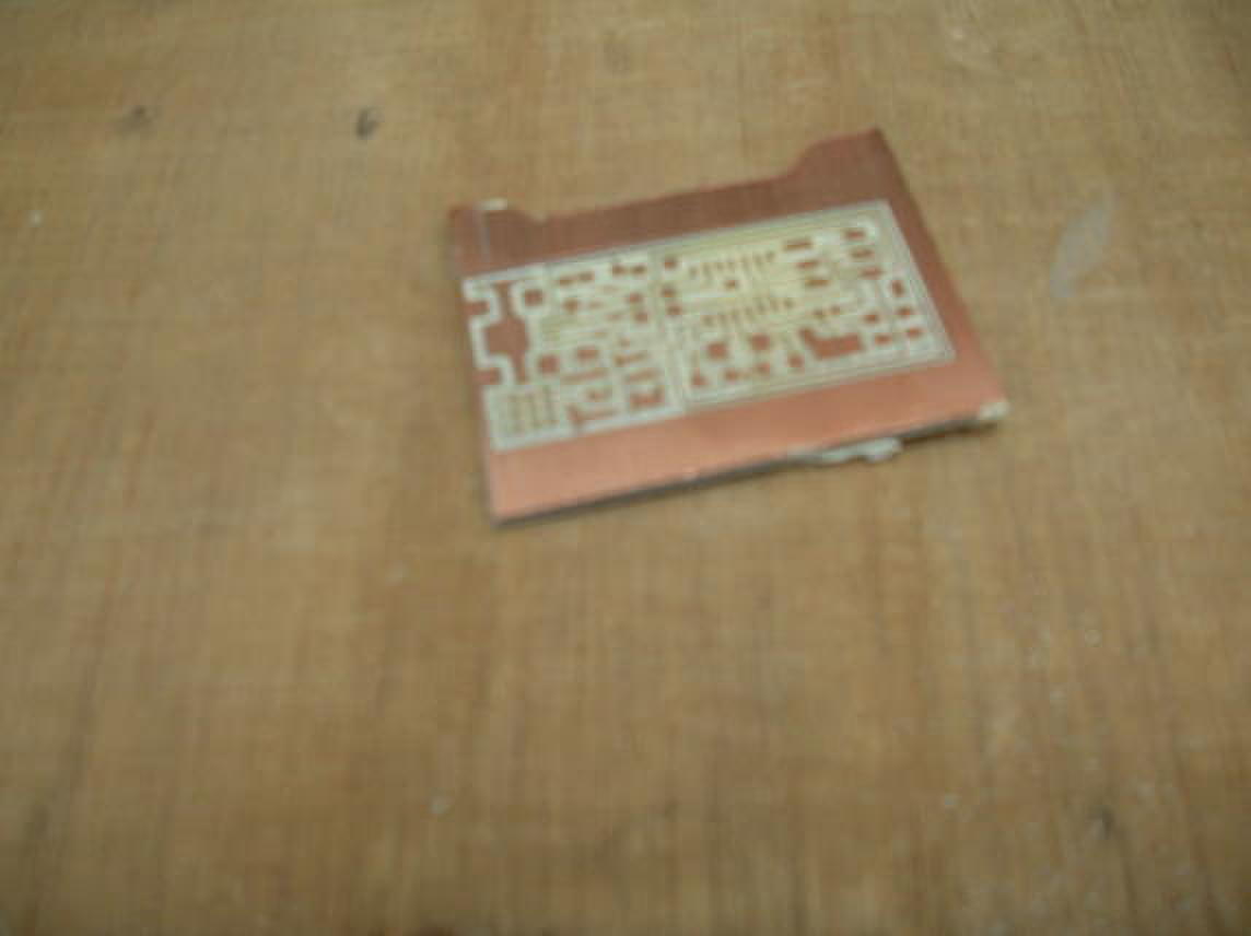
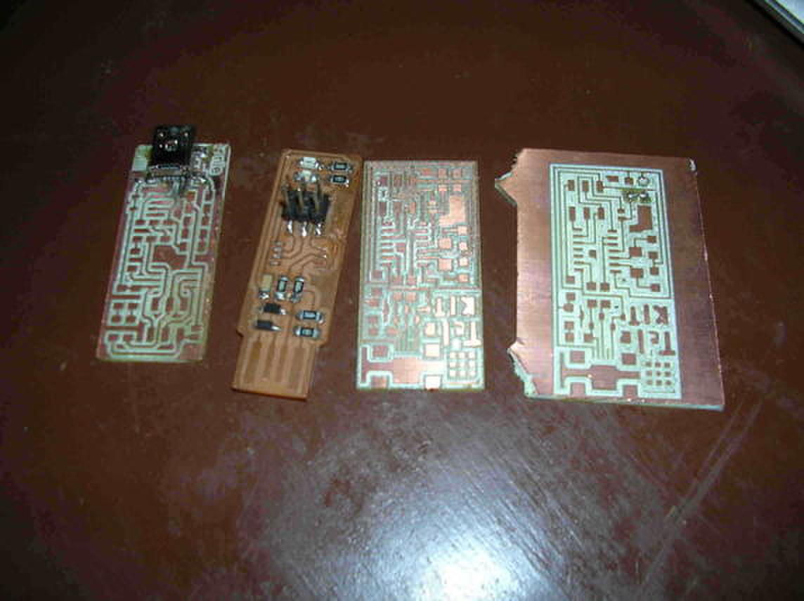
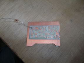
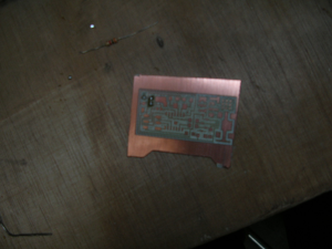
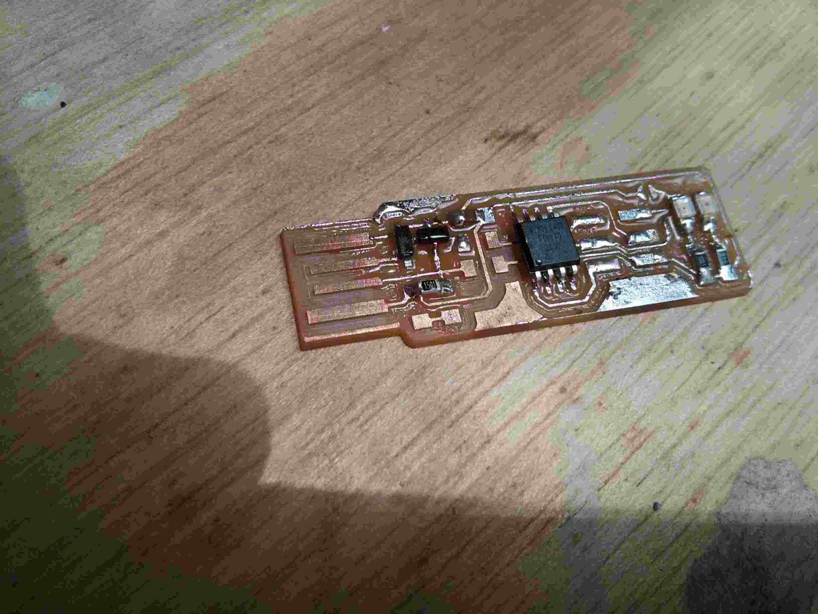
The resulting board we made as a group
Using mods.cba.mit.edu gave us problems. It generated G-code that LinuxCNC did not recognize. It would not load G-code files produced by mods.cba.mit.edu.
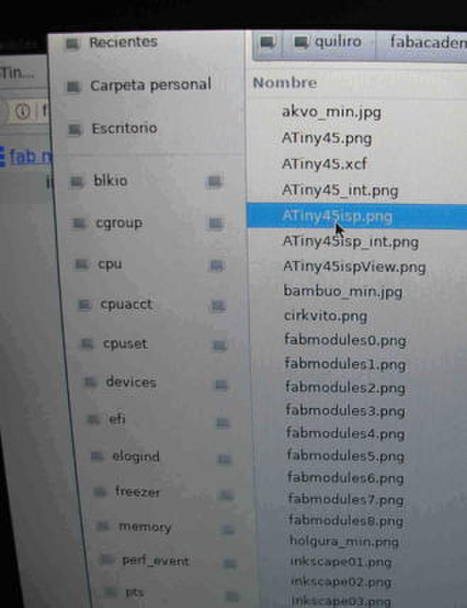
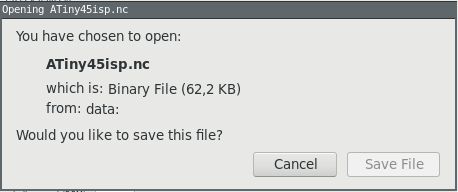
When opening that website, the code (which can be downloaded for local use) presents several modules for the various tasks done to FabAcademy files. For transforming PNG files for use with the CNC, I followed this process:
This file did not work in Axis software from LinuxCNC.
Inkscape can produce G-code! I have still to understand how. But, by reading the output file, I have found codes:
There are instructions on Gcode Tools.
I could not generate this file in Inkscape.
This old version of mods could create a trace in Gcode
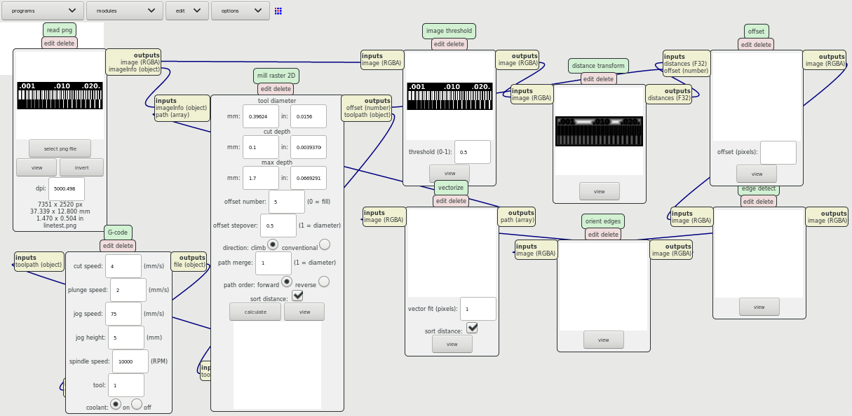
I made Gcode for my board with these parameters.
Which generated this file
But it would not work on LinuxCNC's Axis. Possibly the parameters that were default on Mods were not as good as the ones in FabModules.
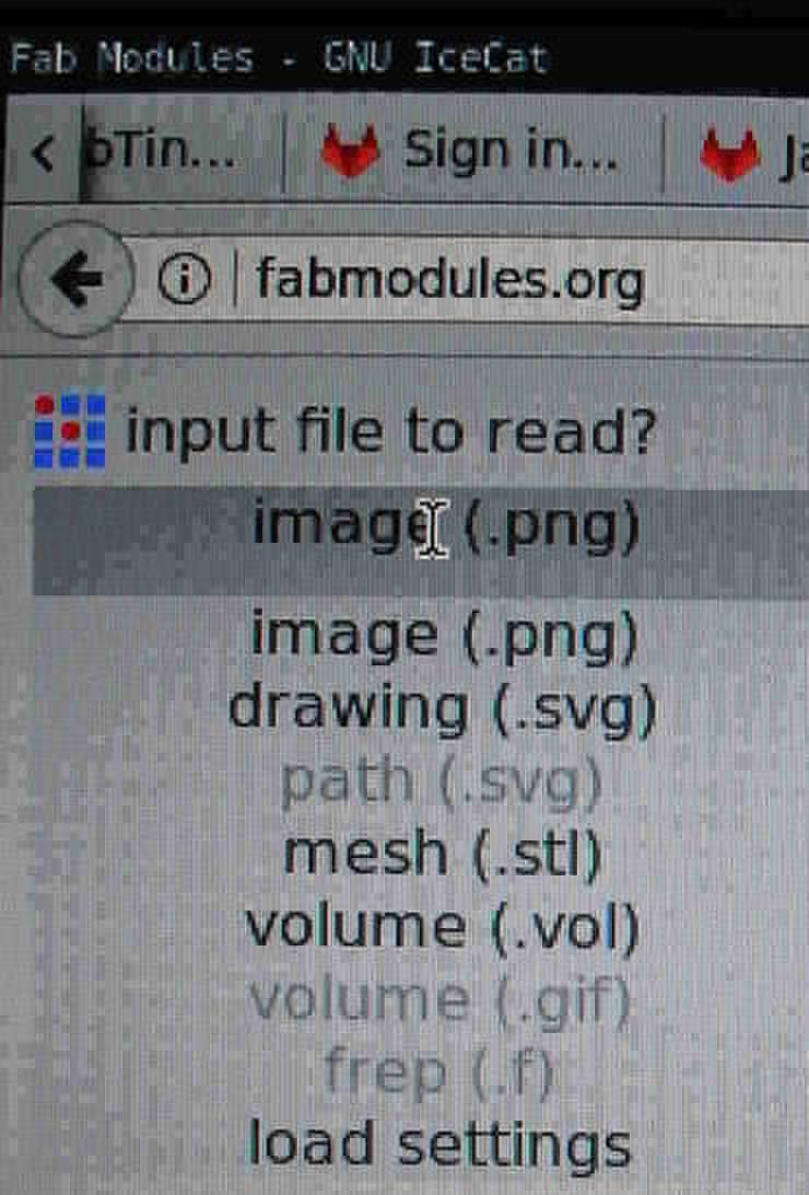
I used the FabModules webpage to generate the files in G-code.
Choose the source file format
Find the file on your drive
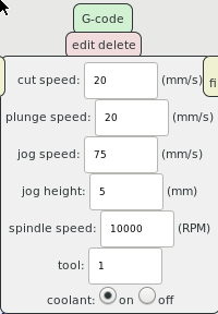
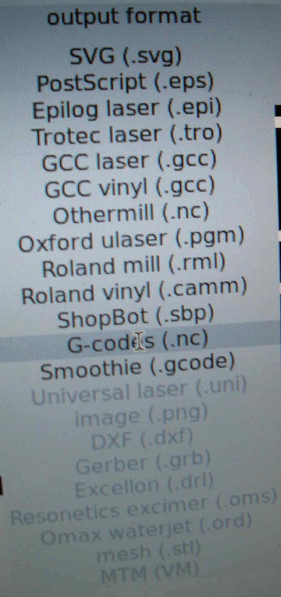
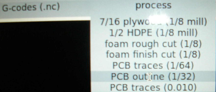
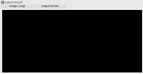
Select the Gcode output format
Select either the milling process
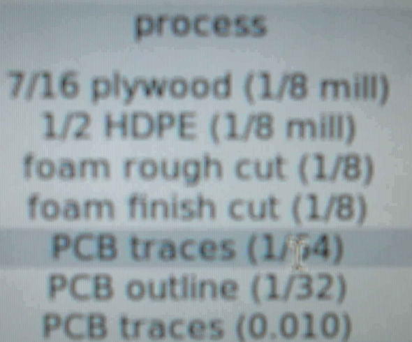
or the cutting process
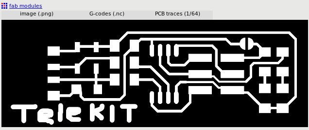
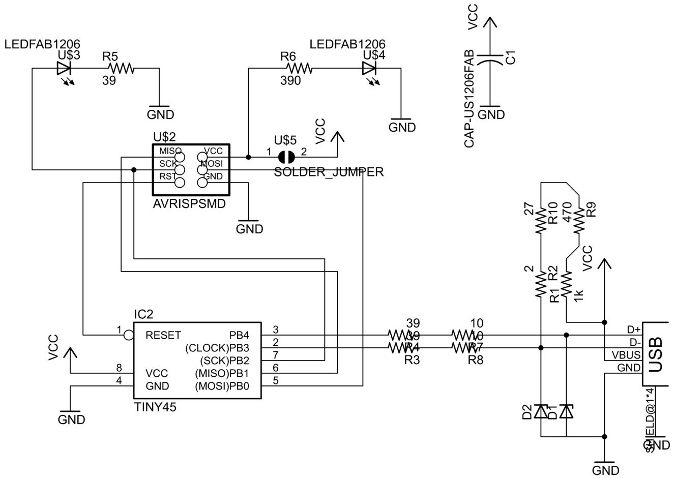
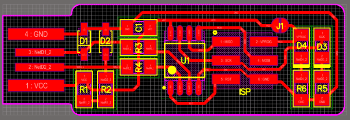
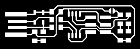
I used the design of the attiny.44.ISP board in raster image. I modified it as follows.
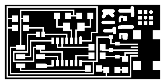
The border is as such.

The components in bold were not available.
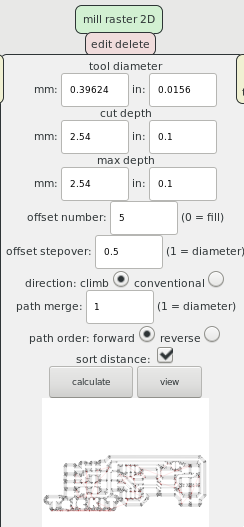
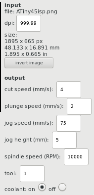
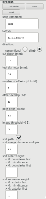
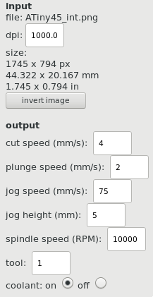
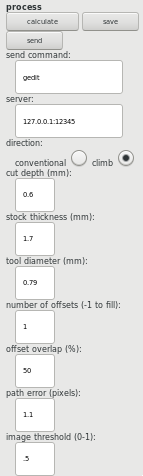
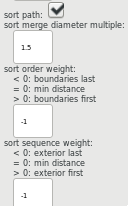
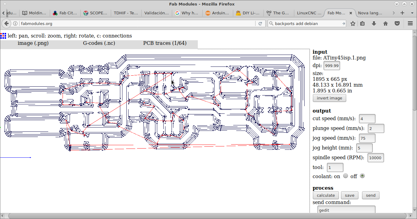
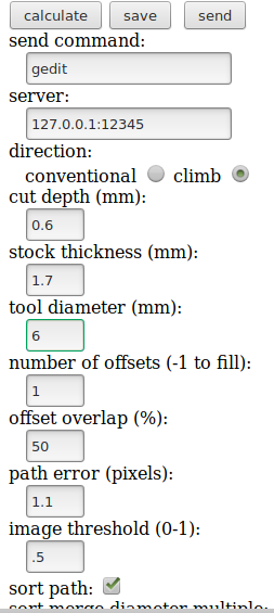
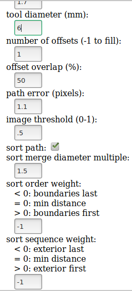
These are the parameters that FabModules expects:
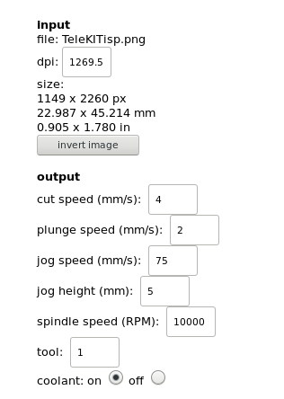
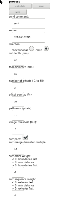
These are the parameters that I have changed:
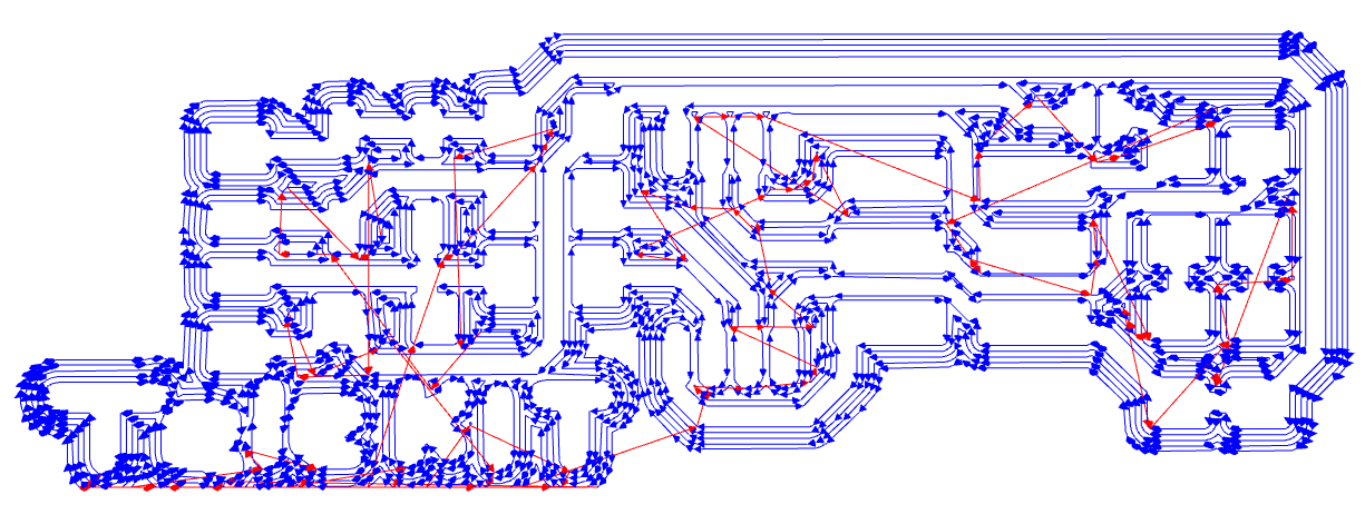
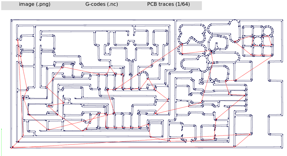
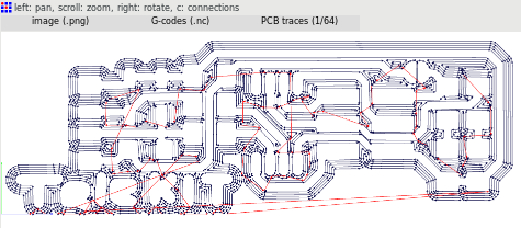
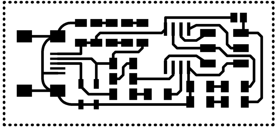
These are the generated paths with 1/64 inch bit generated by pressing the calculate button. (They are used for 1206 size components.)
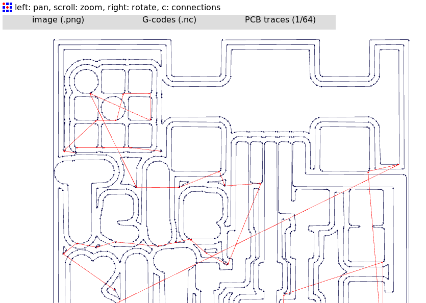
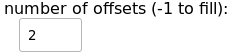
I lowered the number of times the bit cuts because I was told that too many offsets will destroy the paths.
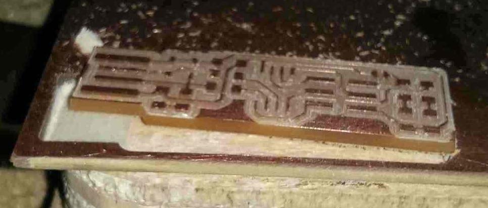
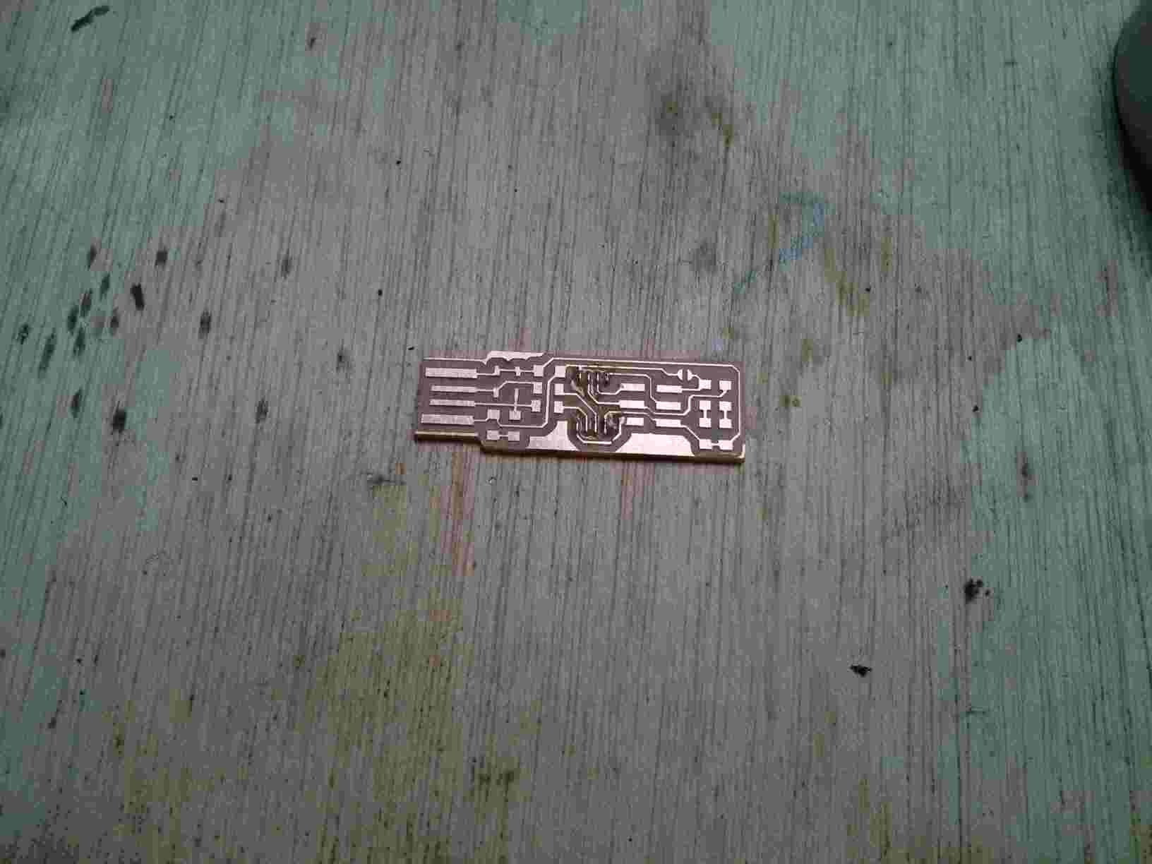
And this is the result.
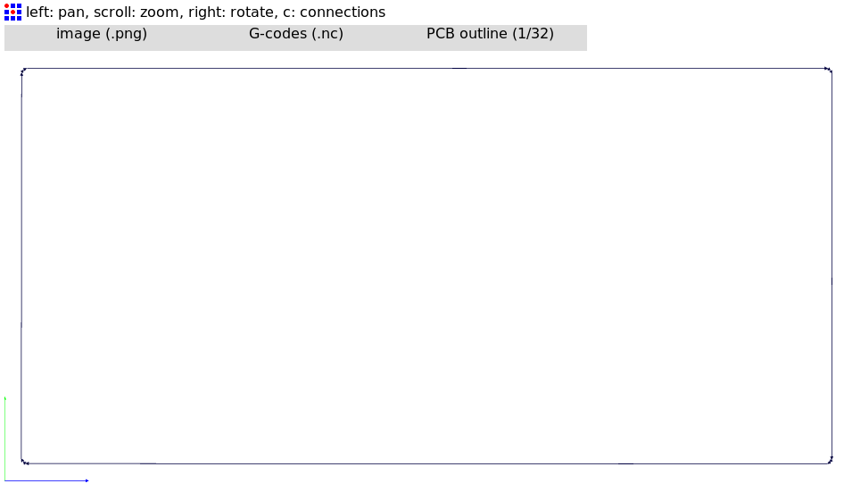
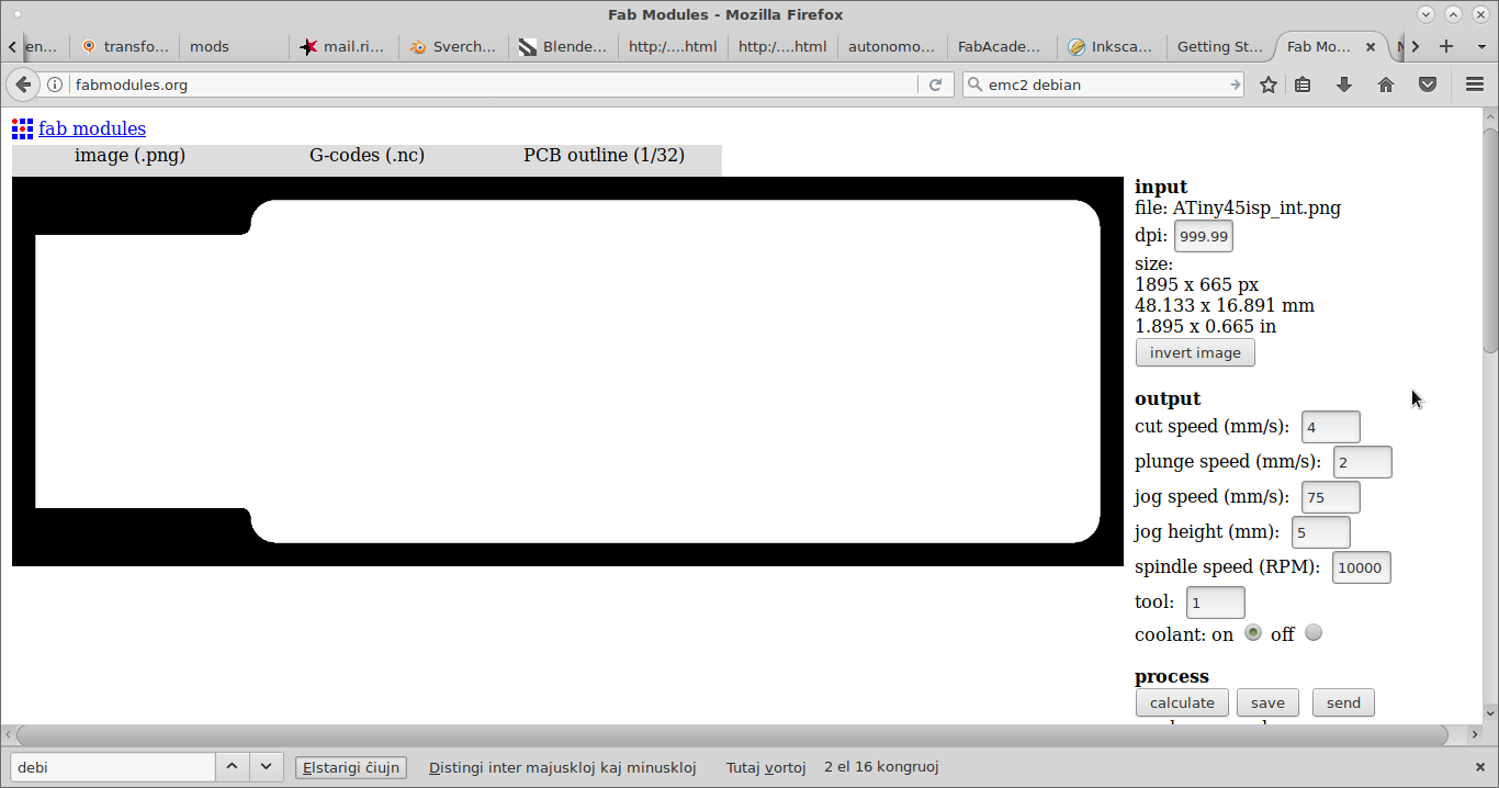
This is the trace for the outer cut with 1/32 inch bit.
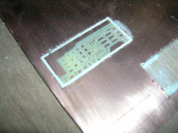
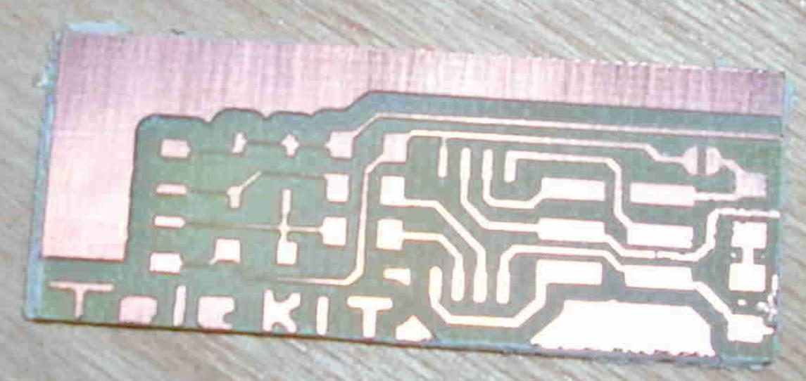
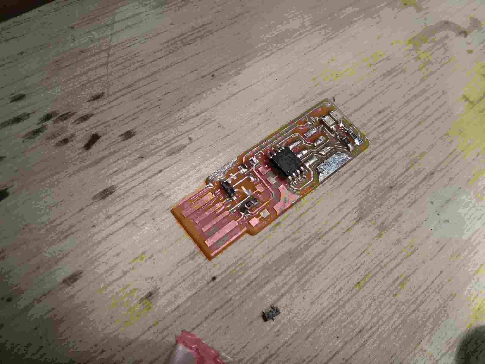
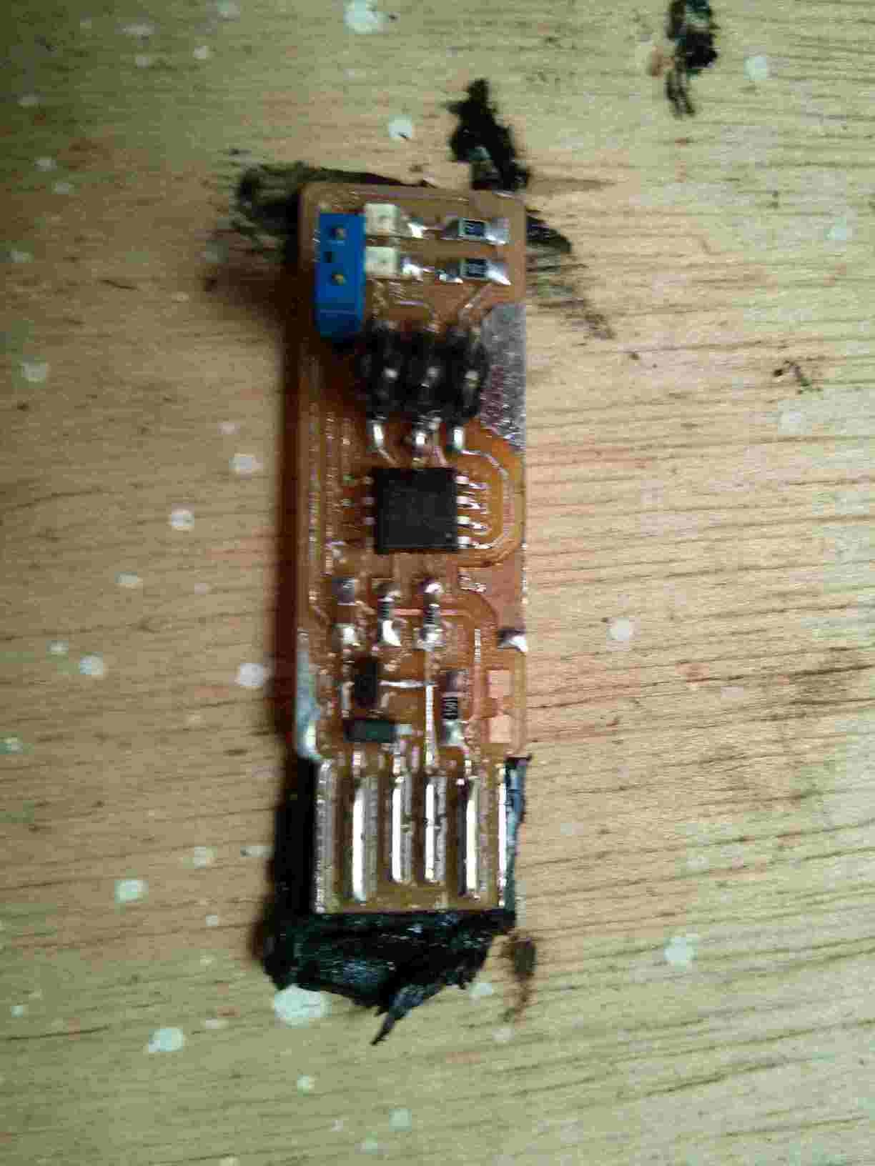
The traces of this board were cut too thin and broke.
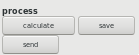
The final G-code for the traces is saved as an NC traces file as well as the cut file. These are the traces file and the cut file for another version. These are the GIMP files with the modified image source for sending to FabModules.
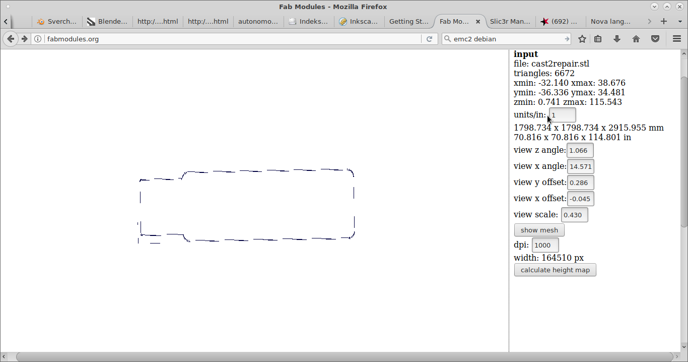
This model was not possible to construct. All the components were not available.
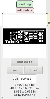
Using this image file:

I followed this process for milling
And this process for cutting

I test my classmate's design.
Here are the components. I source a combination of resistors in series to replace the ones I could not obtain.

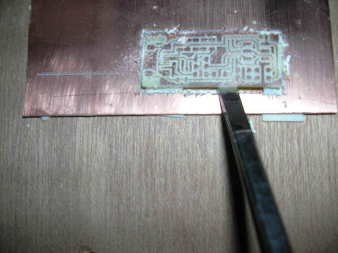
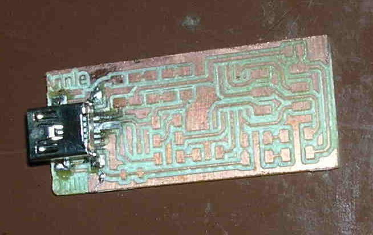
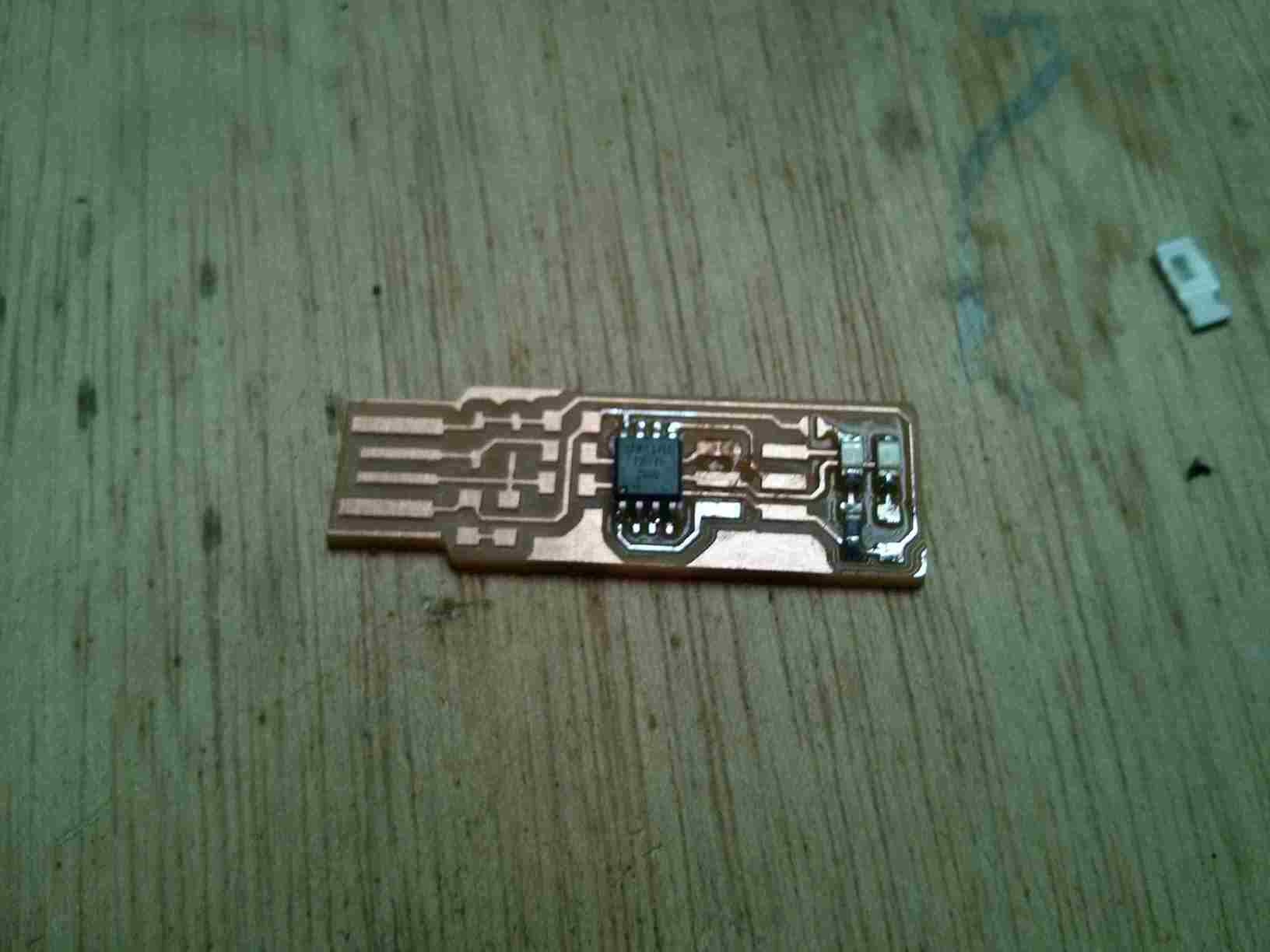
The new circuit is not good. The design looks good. But (in production) it has a joint in traces of the board. I must mill another board.
I used the image from the FabTinyISP tutorial and that worked flawlessly.

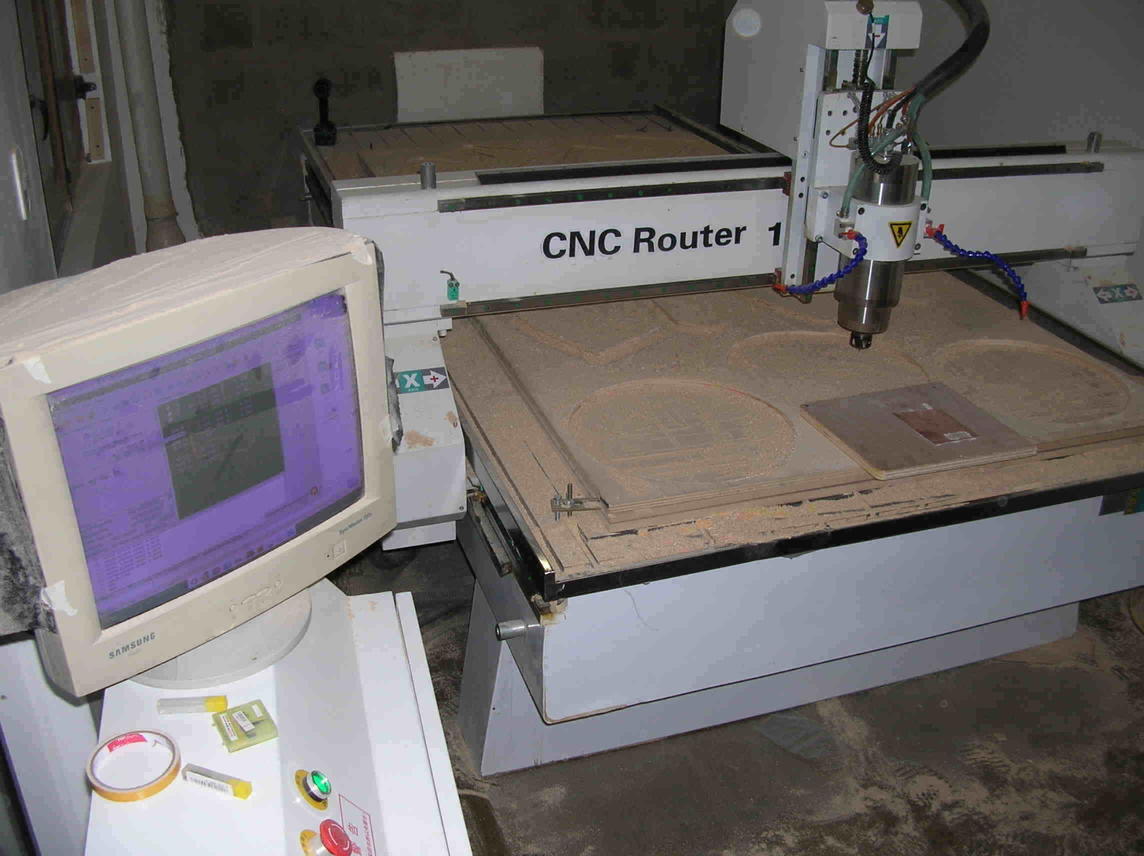
I milled and cut the board with libre software from LinuxCNC which is installed in a computer that is connected to the milling machine. I loaded the G-code by way of a USB flash memory.
Disclosure: Some of the pictures are not of my board because we worked together with a peer on some of the processes.
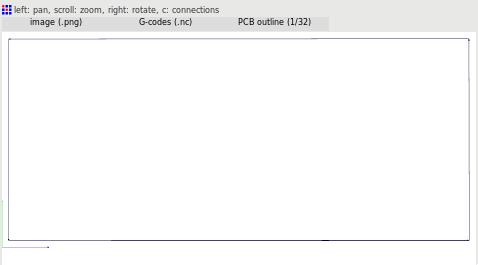
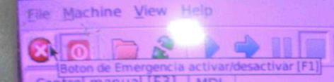
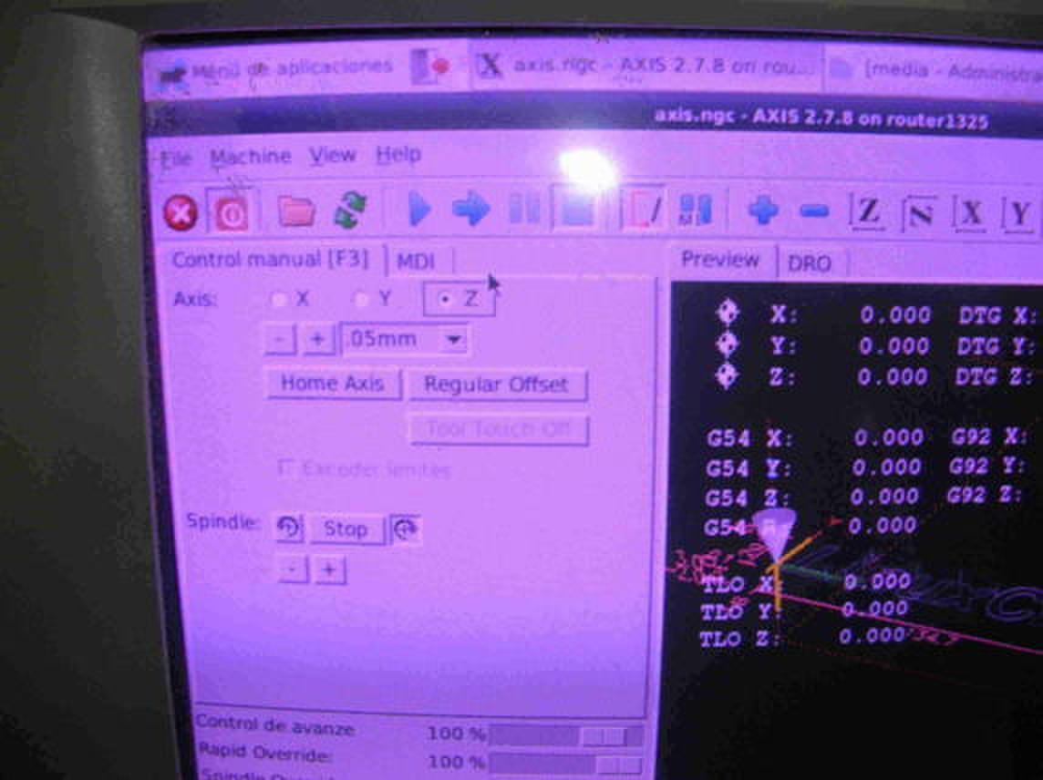
This is Axis' interface
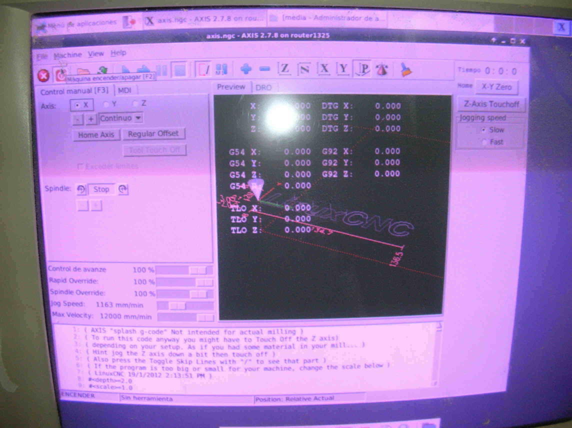
We must first deactivate the emergency button.
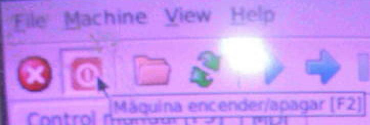
Then startup the machine.
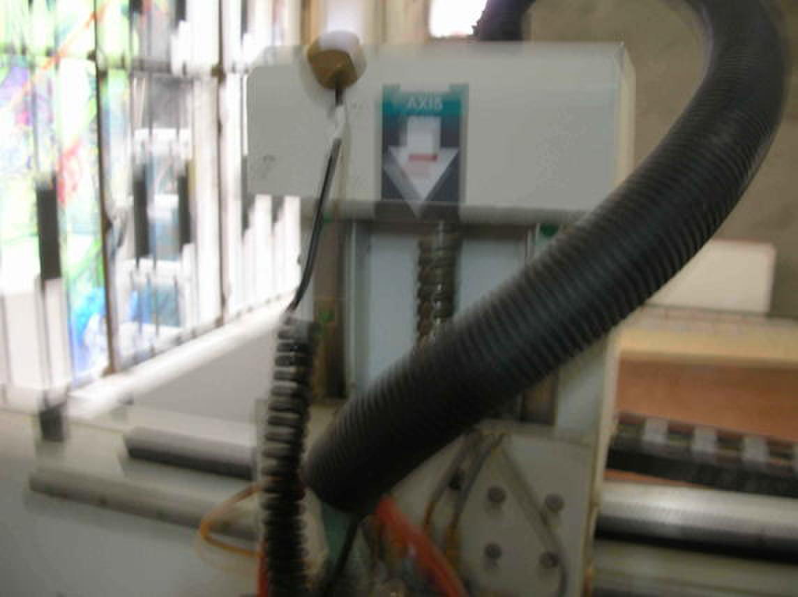
Select the Z axis to setup
Create a new Gcode file with Autolevel software. Load this new file in Axis software and start the step by step process.
until the tip senses the board.
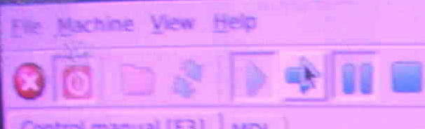
Then press the home button and let the rest of the milling continue automatically (not step by step).

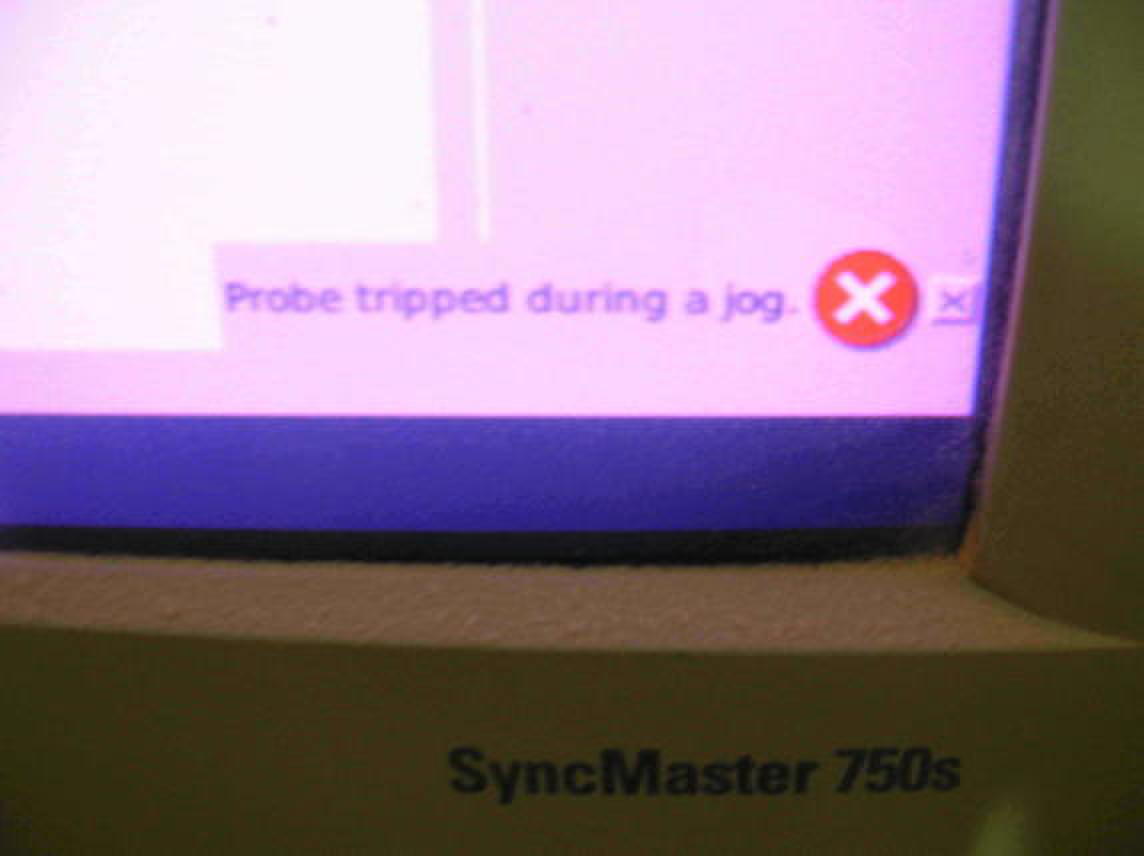
The second error message always appears. But the milling continues normally.
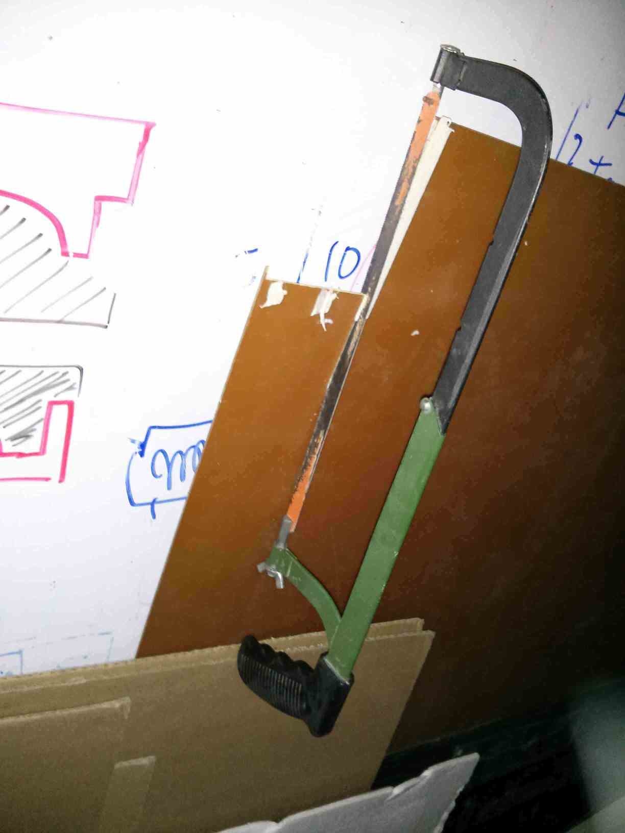
Cutting a piece of the big board to fix to the table.

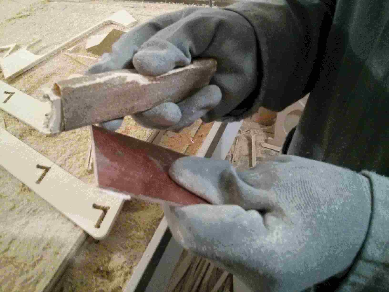
Sanding the board to have a uniform Z axis correct sensing.
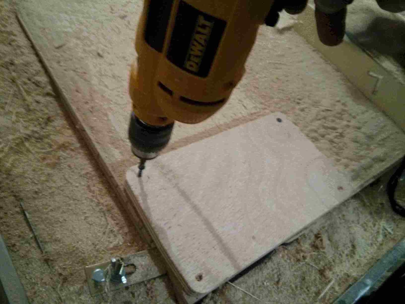
Fixing a plywood board to hold the PCB to the table.
Fixing the PCB to the plywood with double sided tape.
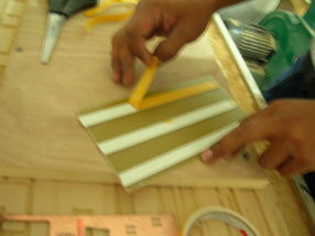
The board is now fixed to the plywood.
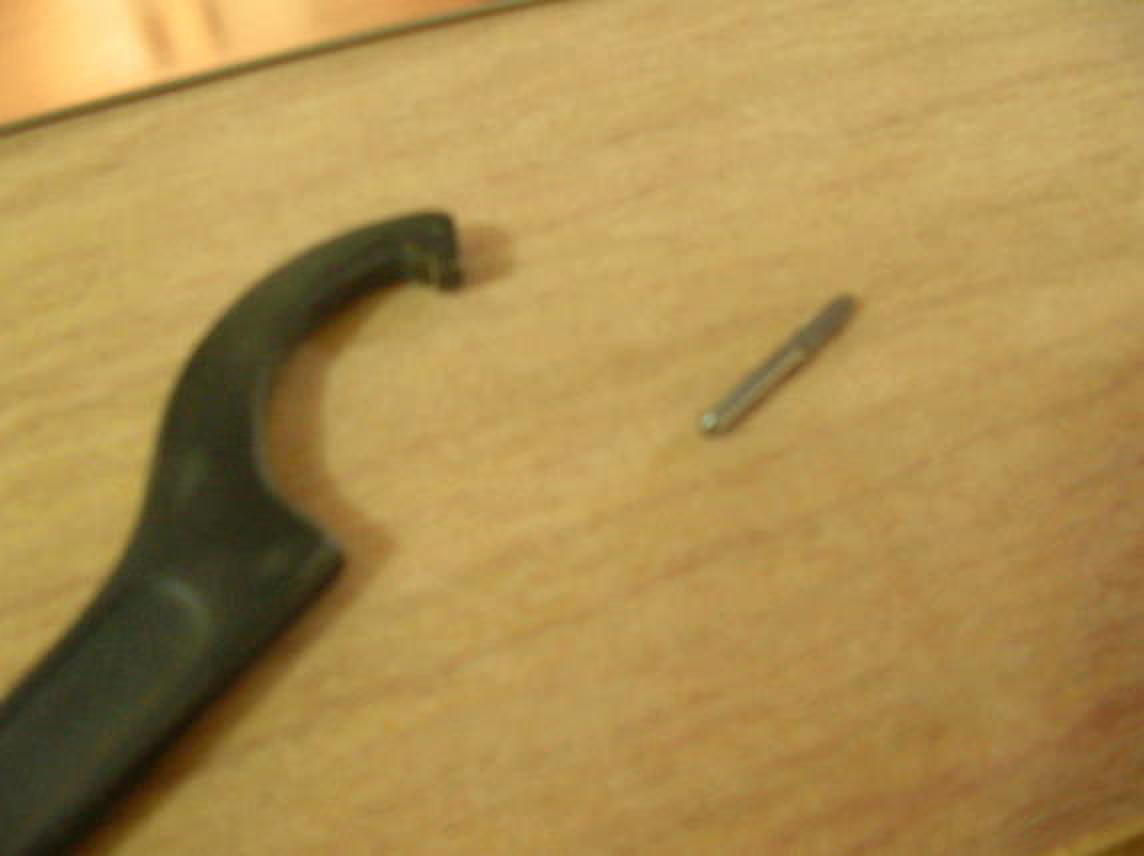
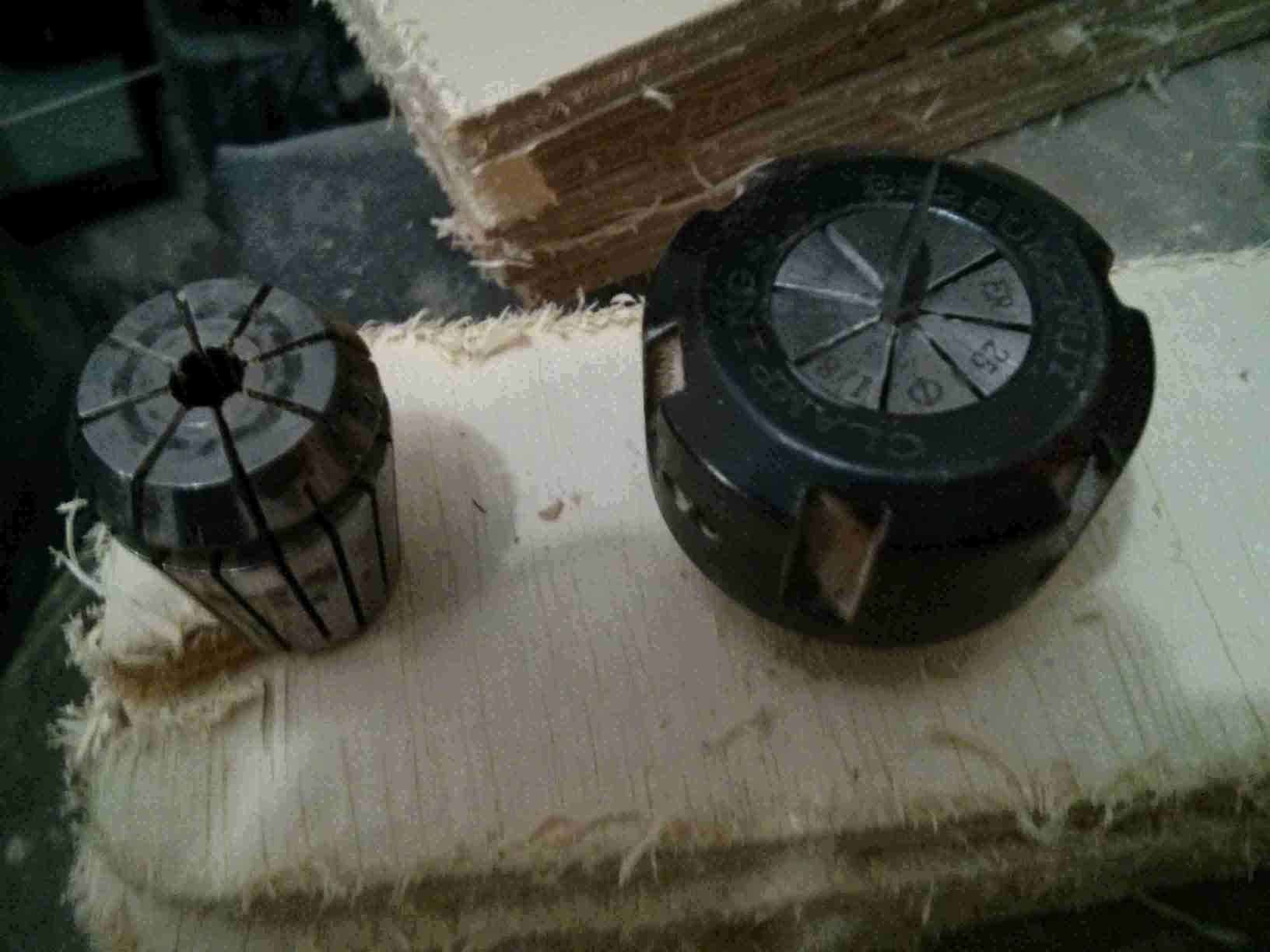
Tools
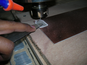
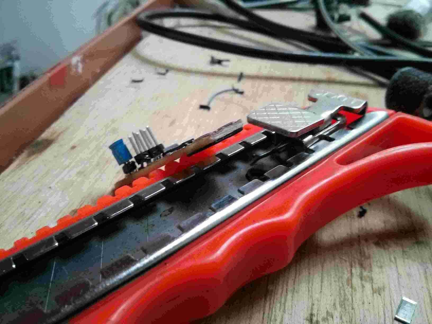
I use the CNC sensor for the computer to detect the height of the drill bit.
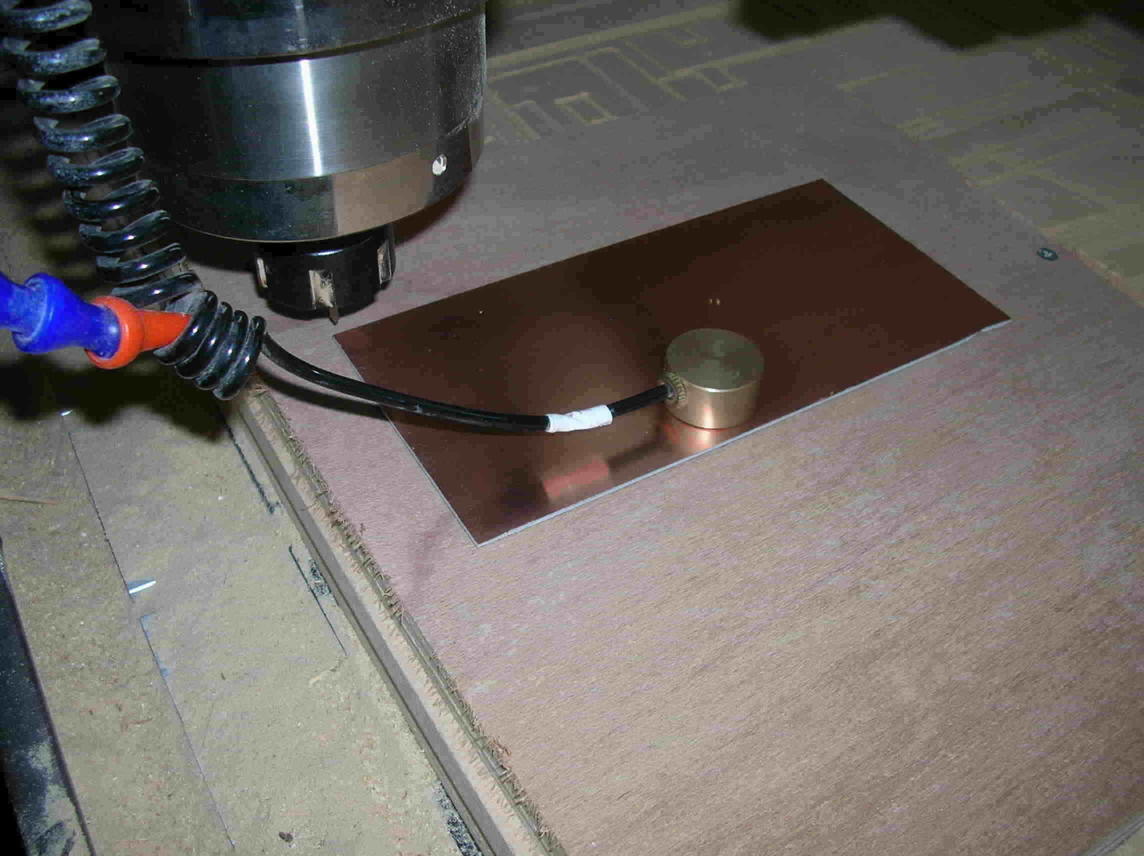
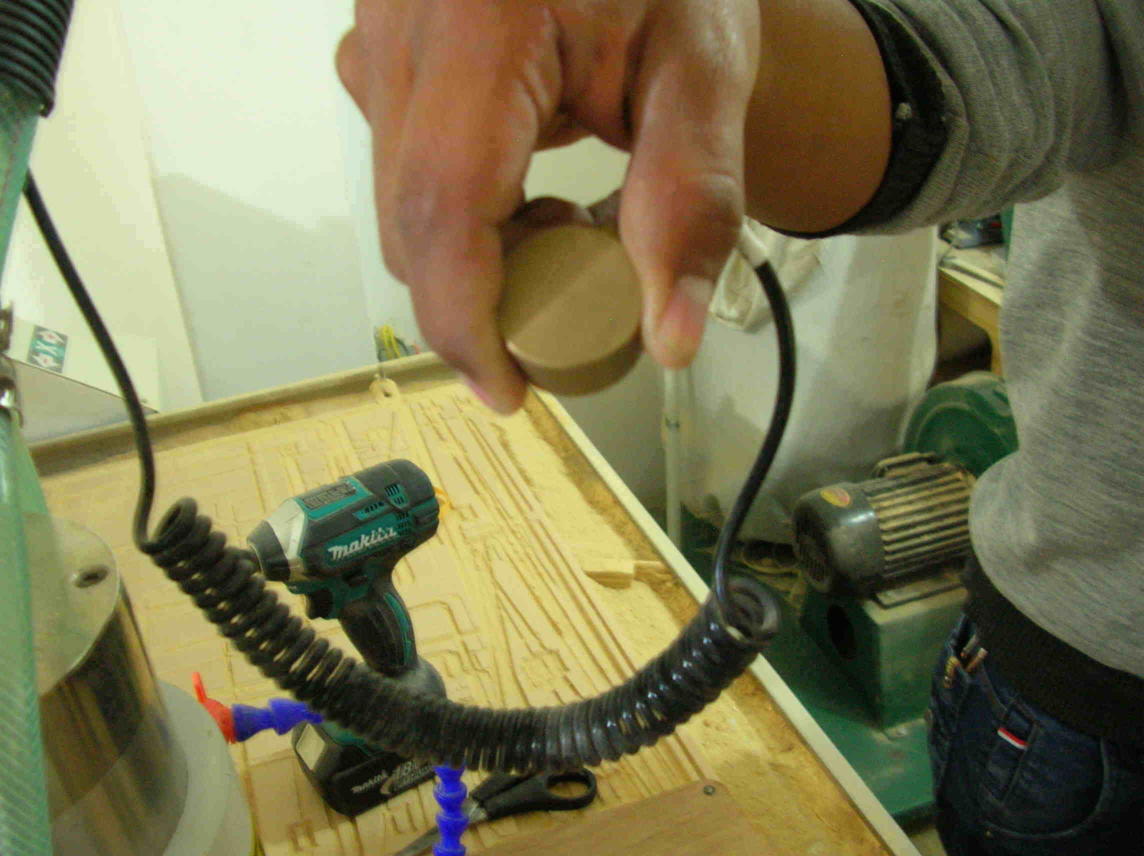
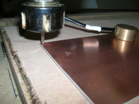
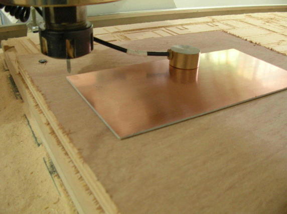
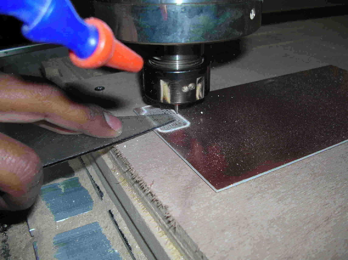
Using the sensor to align the Z (vertical) axis.
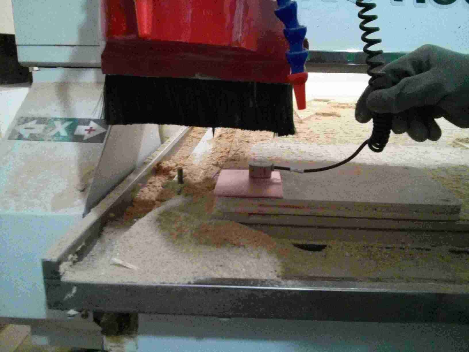
And fix the sensor up high once we want to start milling
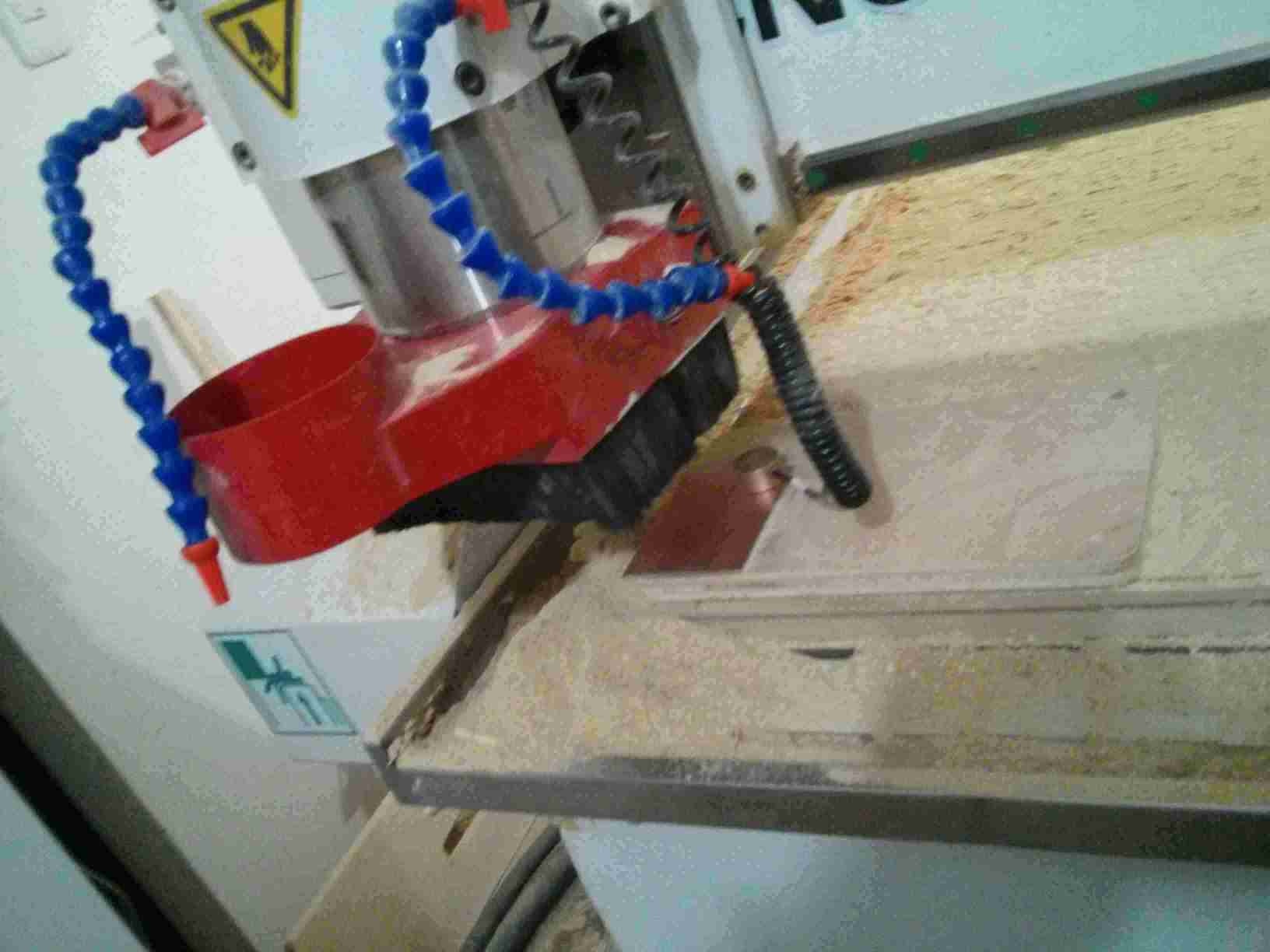
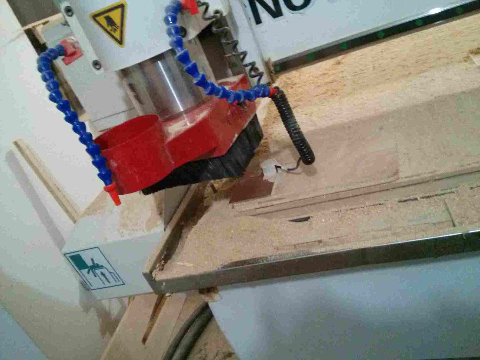
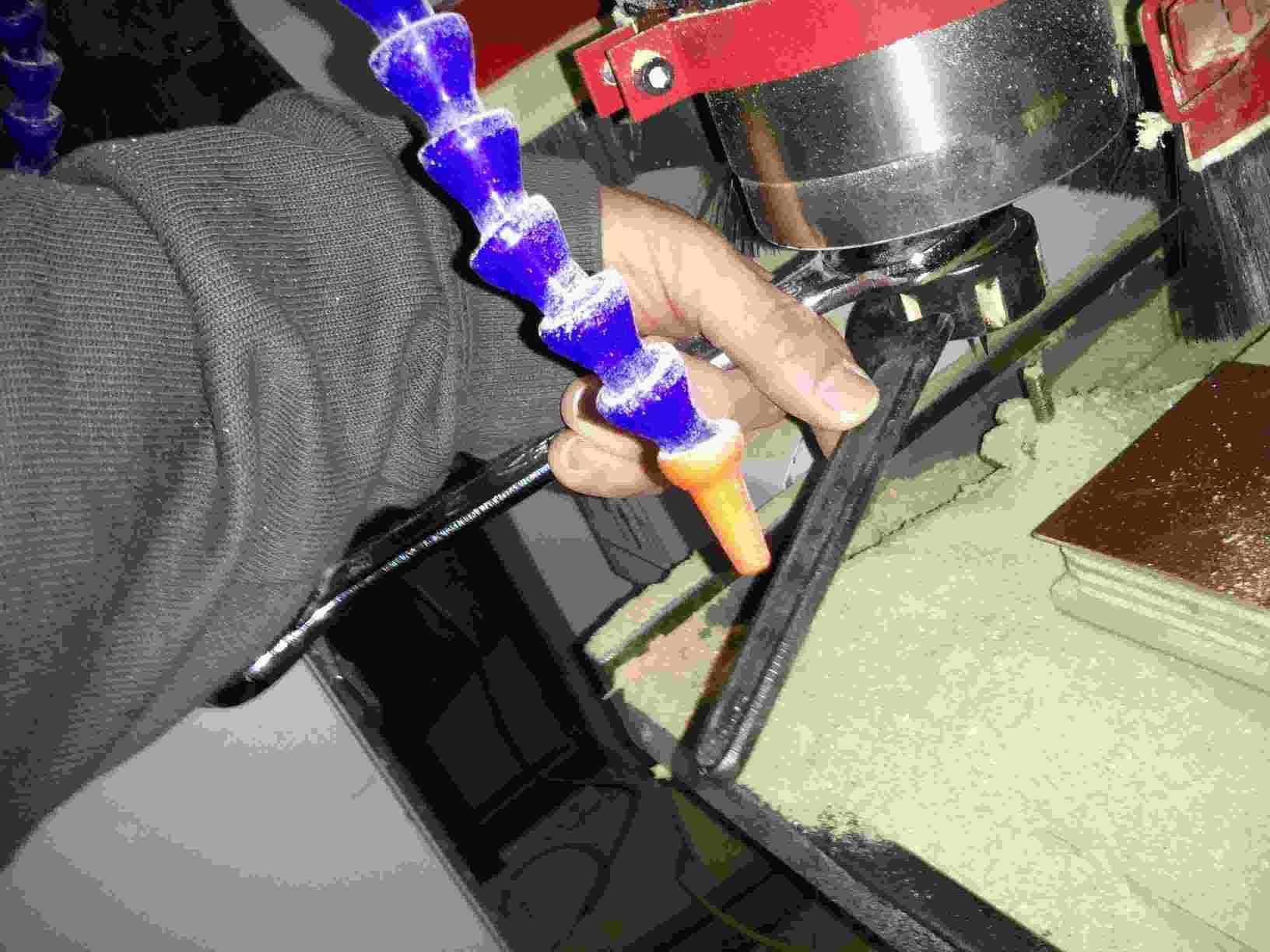
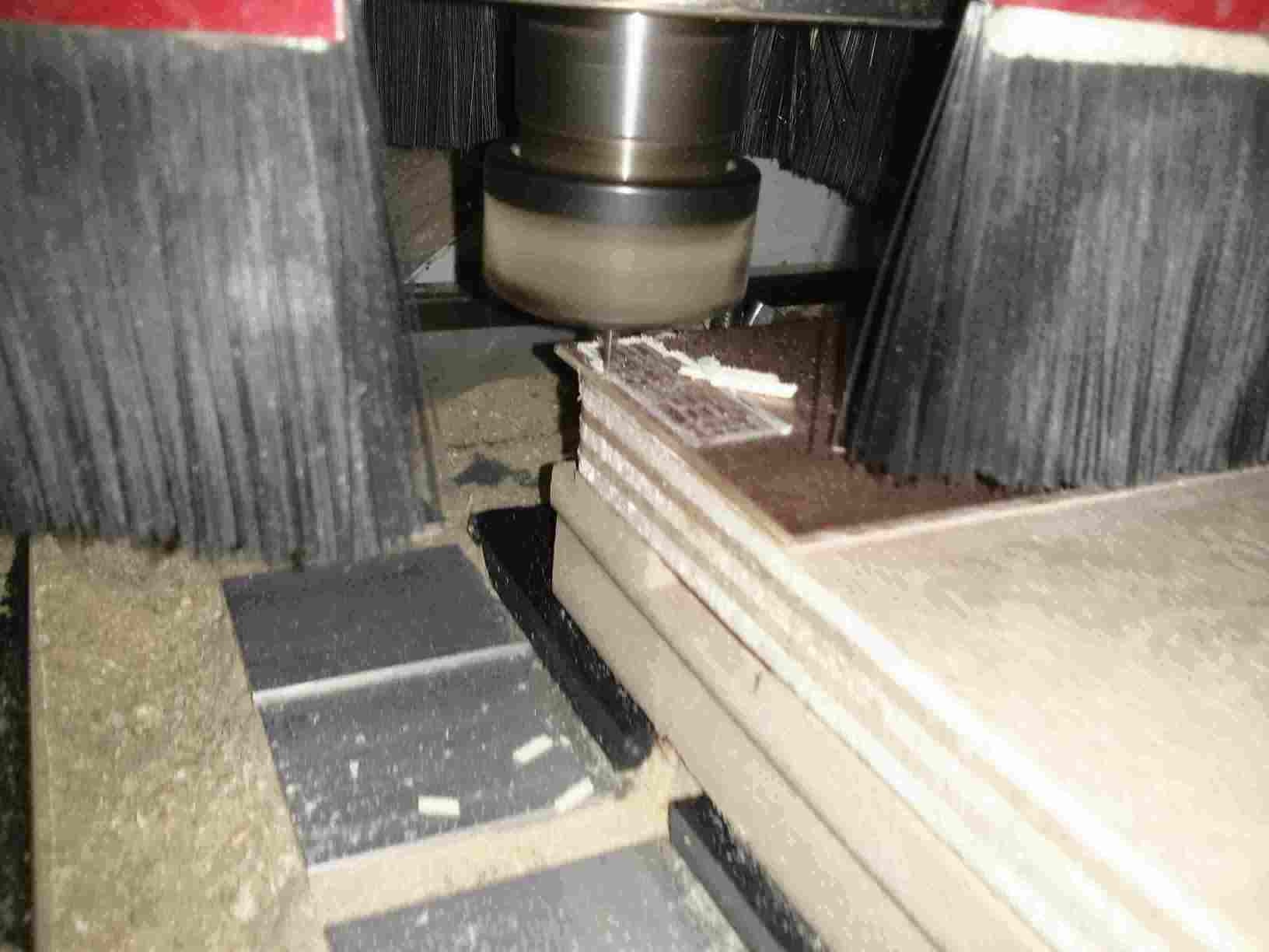
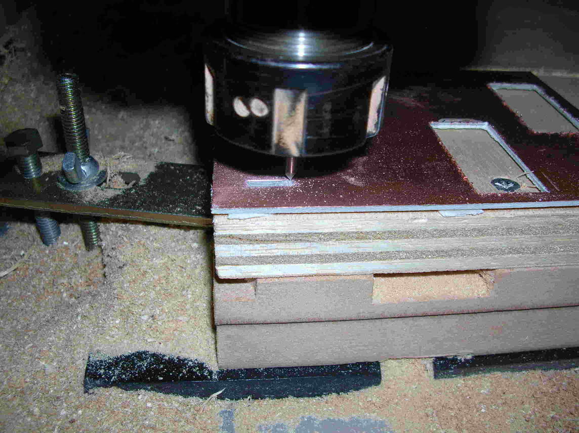
The board is not horizontal. So we held down the board while cutting. This is a very dangerous practice. Latter, we learned how to level the board in order for the cut to be at the same depth throughout the board. (This is not my board. But this shows the reason I had problems with mine.)
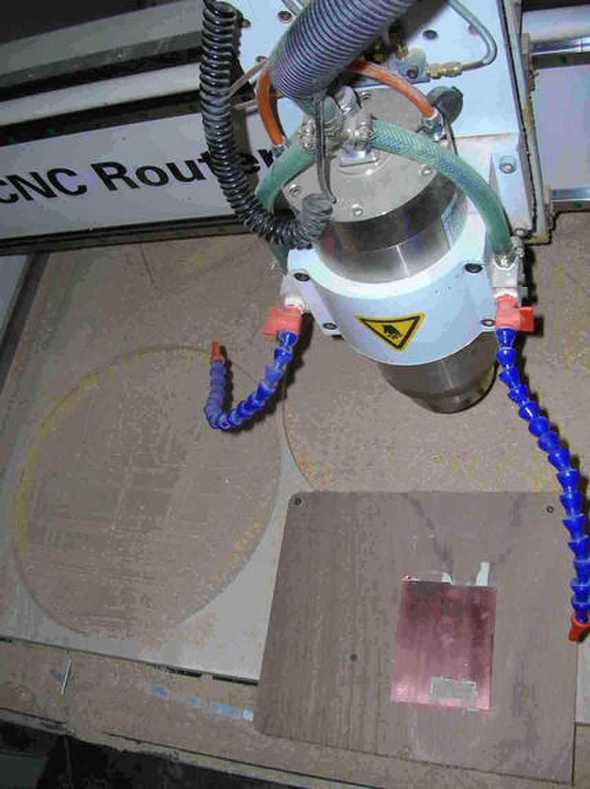
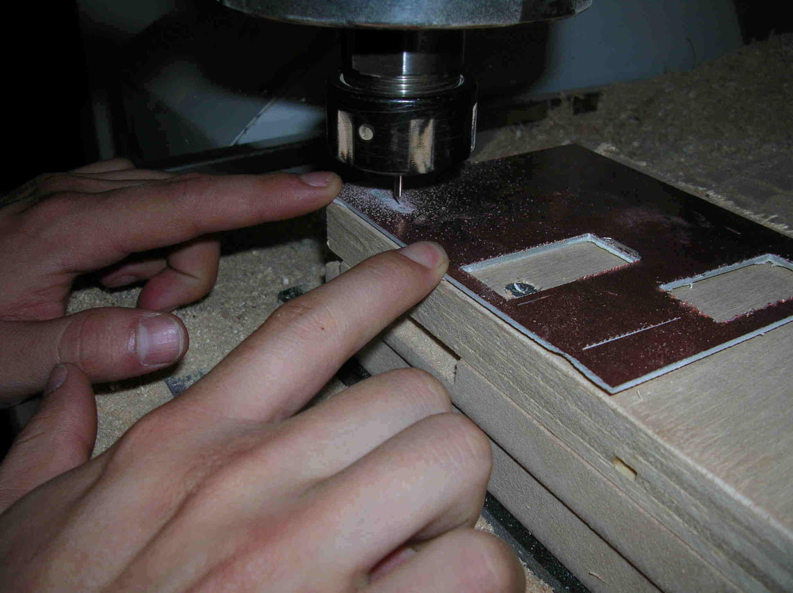
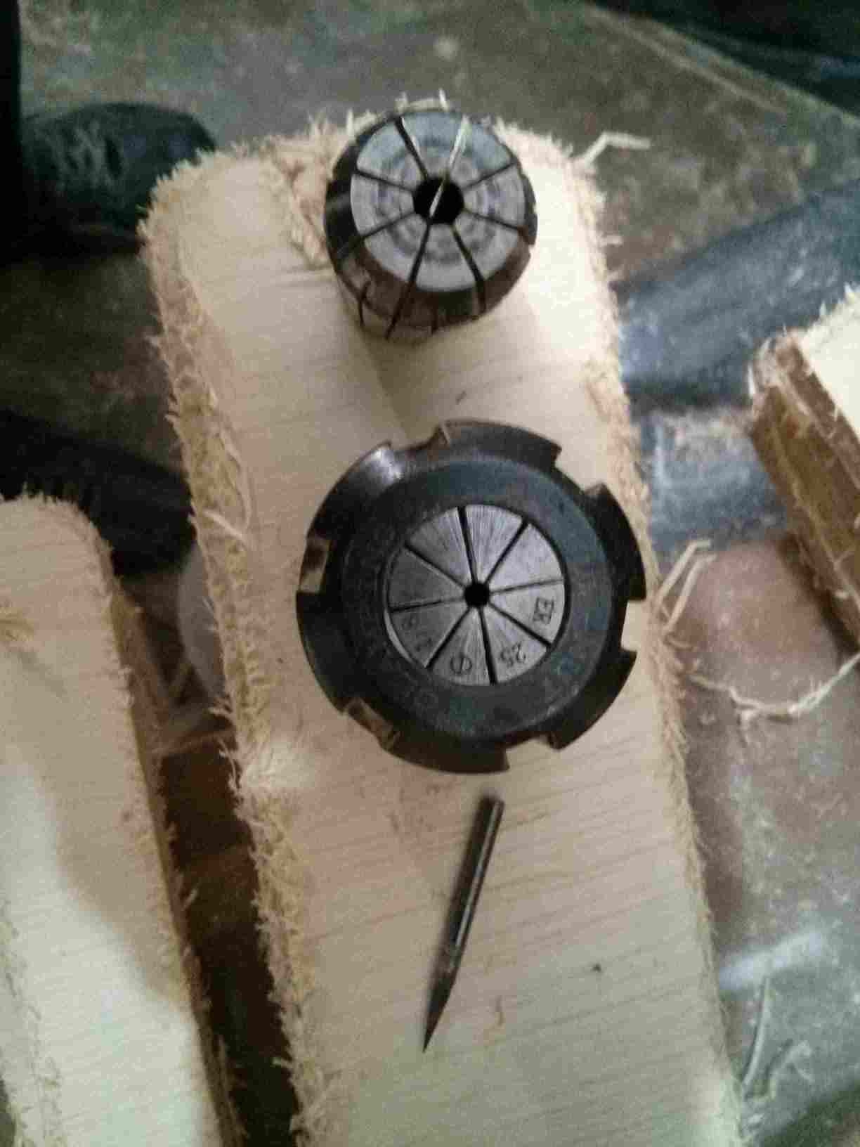
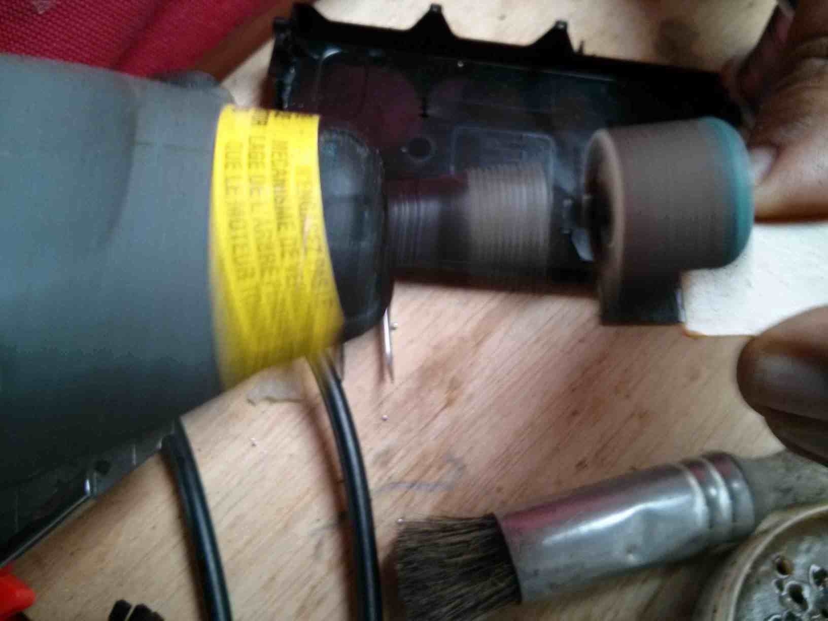
We form the board with one mill bit and cut it with another mill bit.
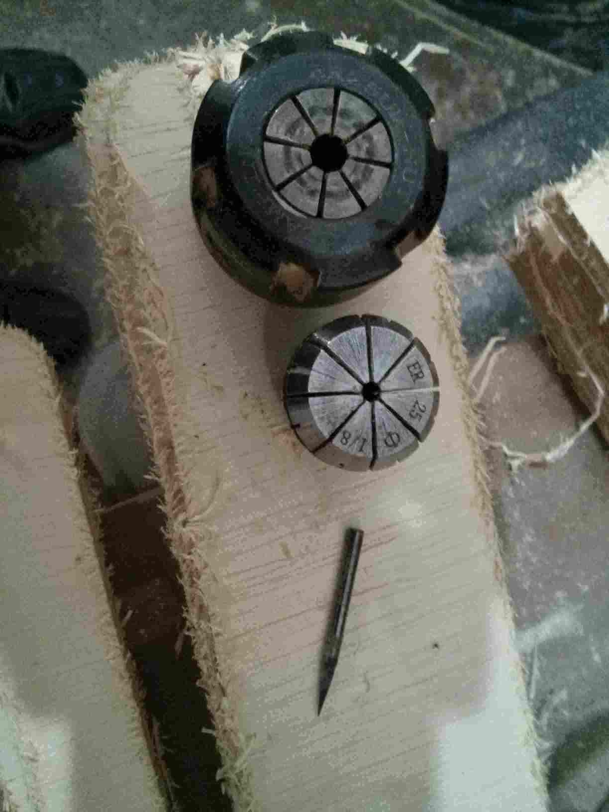
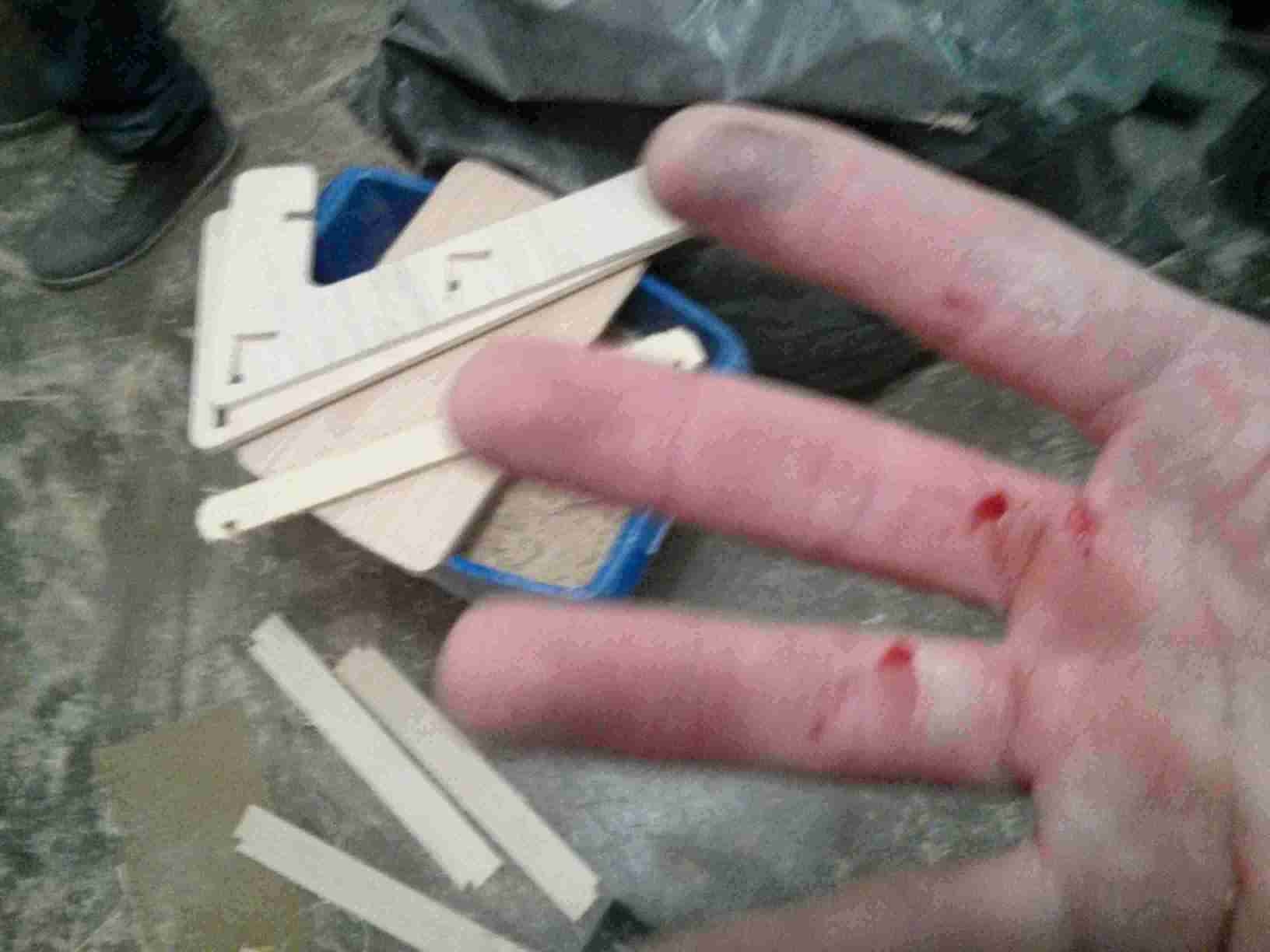
I was cut by the end-mill when unscrewing the spindle nut that held it. The heavy spindle nut fell on my hand with the end-mill fixed to it. Be careful with sharp tools!
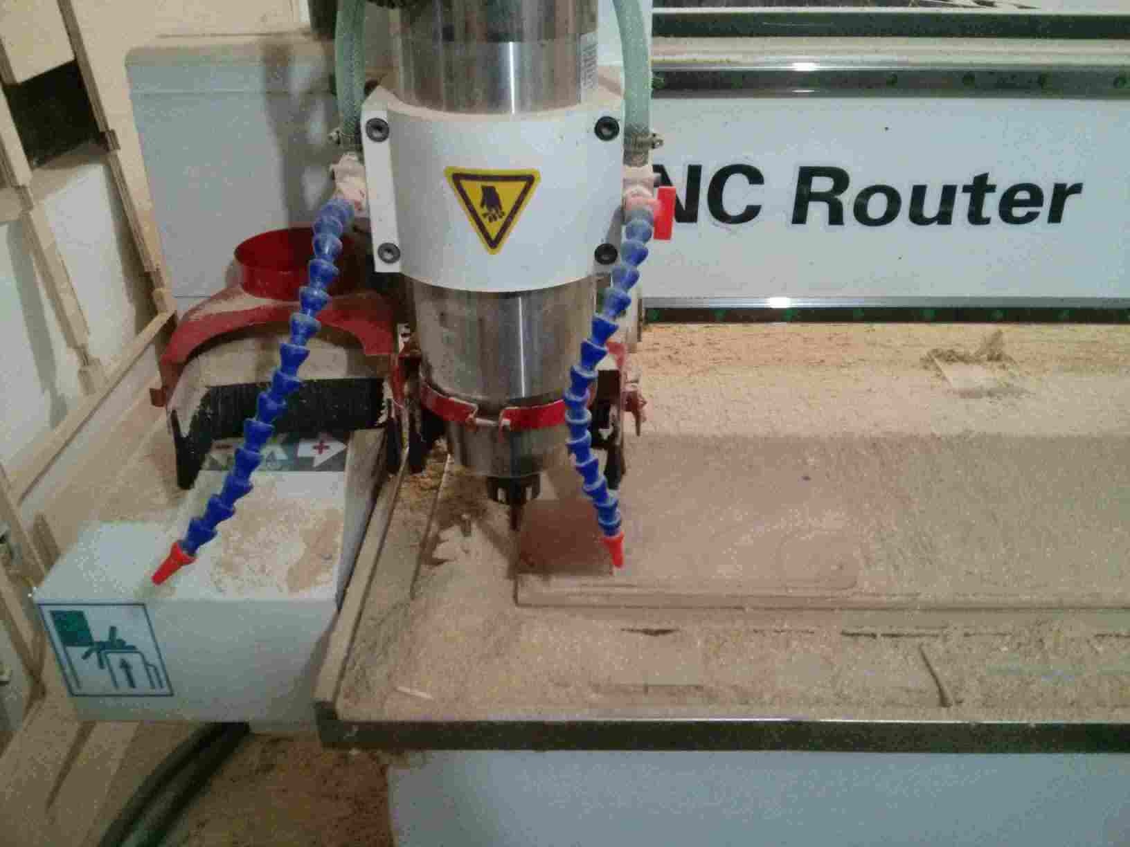
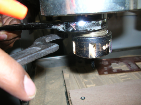
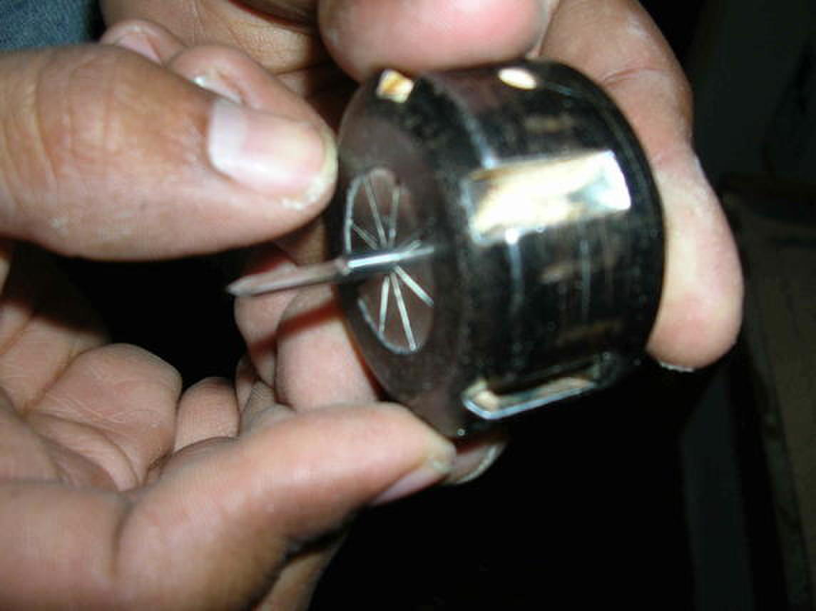
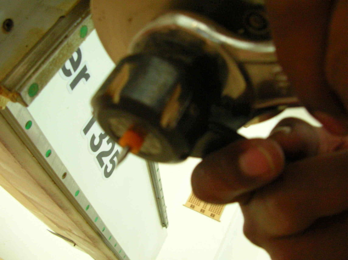
Fixing the cutting mill to the spindle.
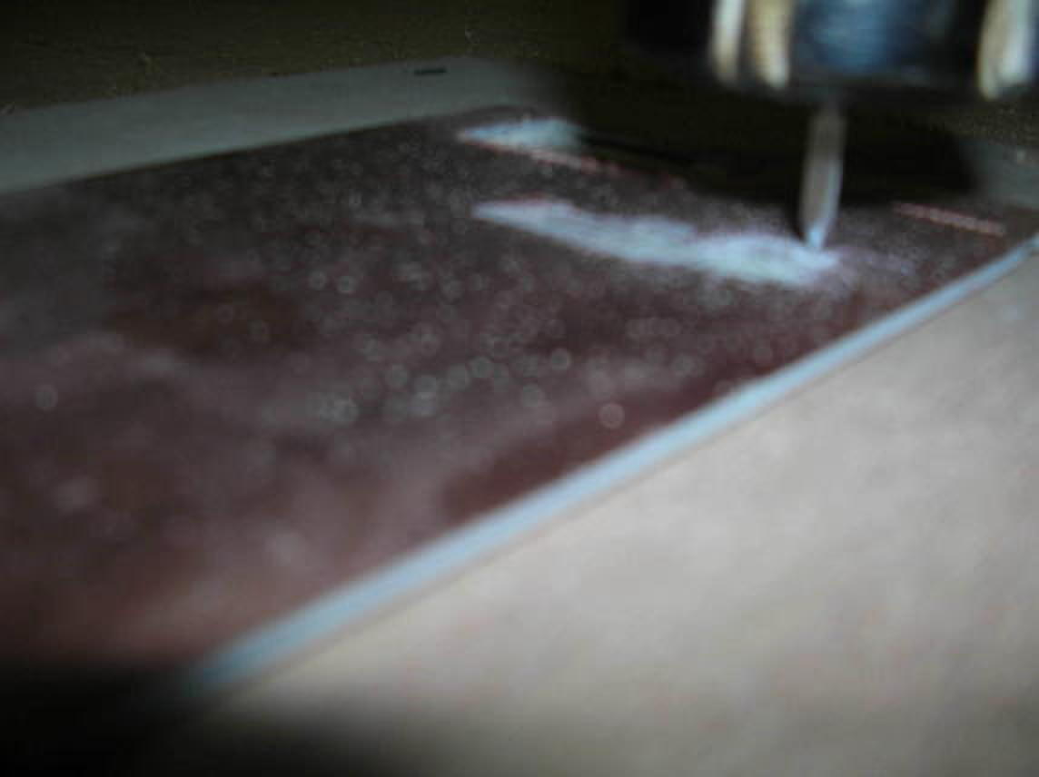
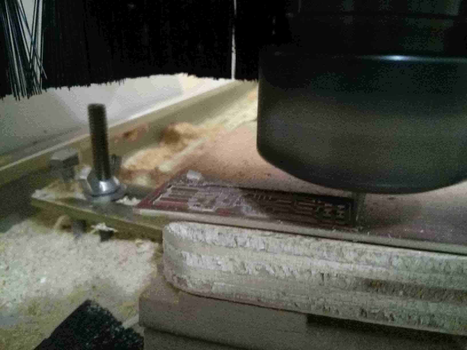
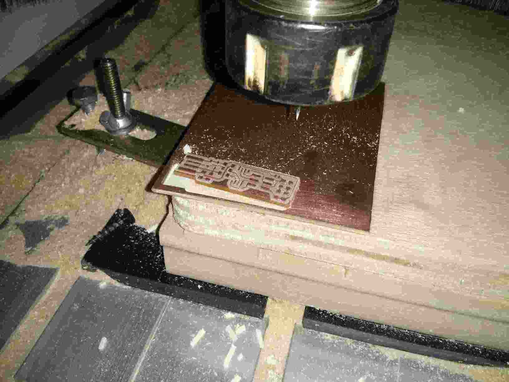
The mill is now cutting the finished board
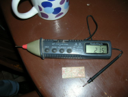
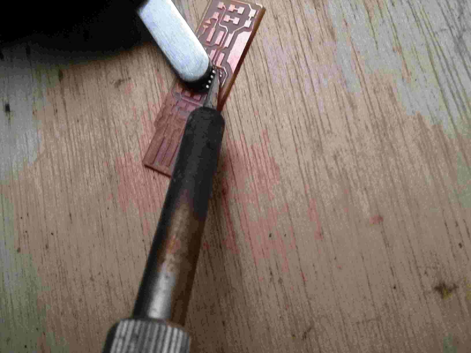
Testing the continuity of the traces on board.
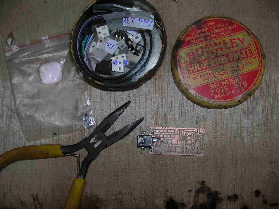
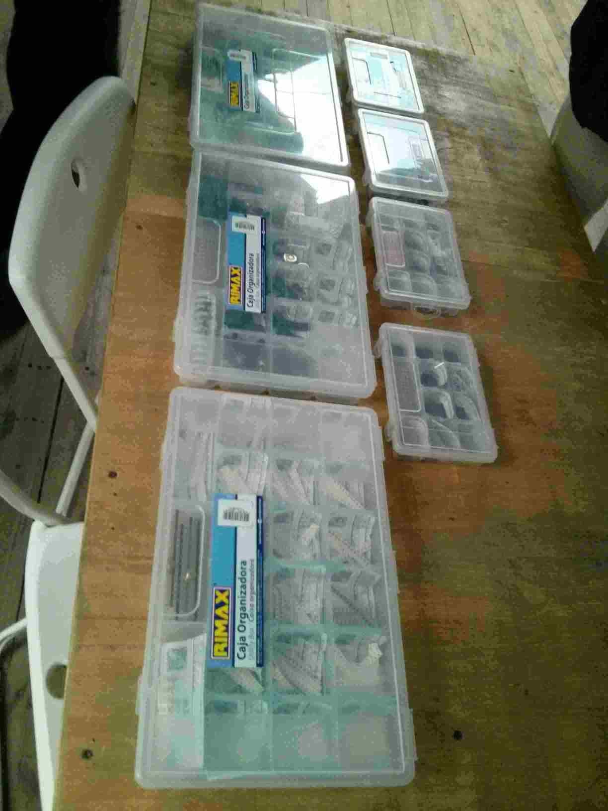
The inventory...better late than never! :-D
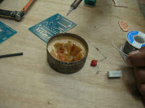
The soldering station at Fablab Zoi has a heated air gun and a hot soldering tip stencil.
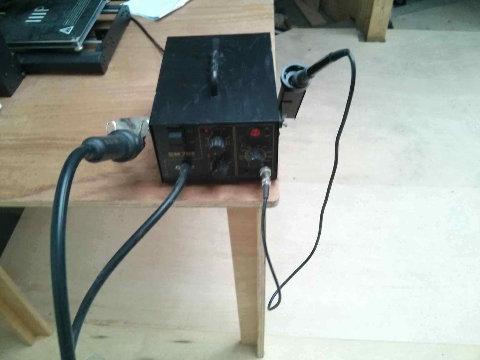
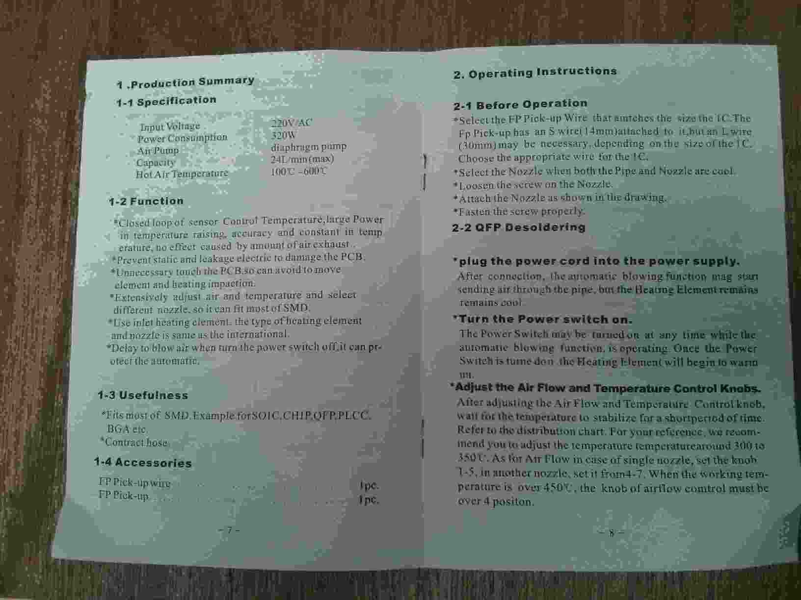
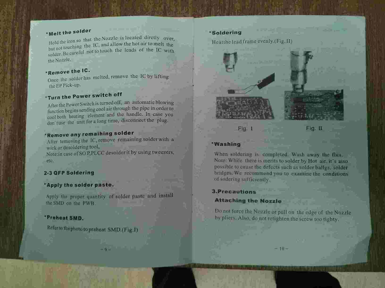
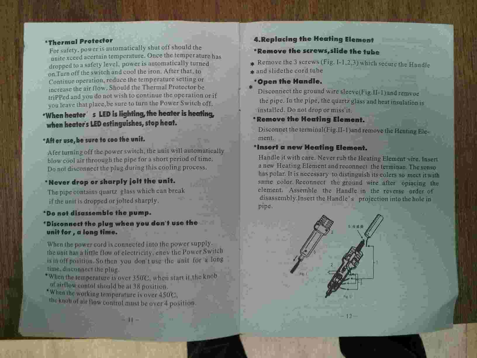
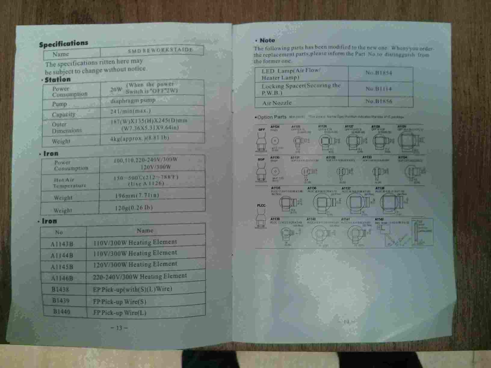
These are the instructions for the soldering station at Fablab Zoi.
Cleaning the solder gun.
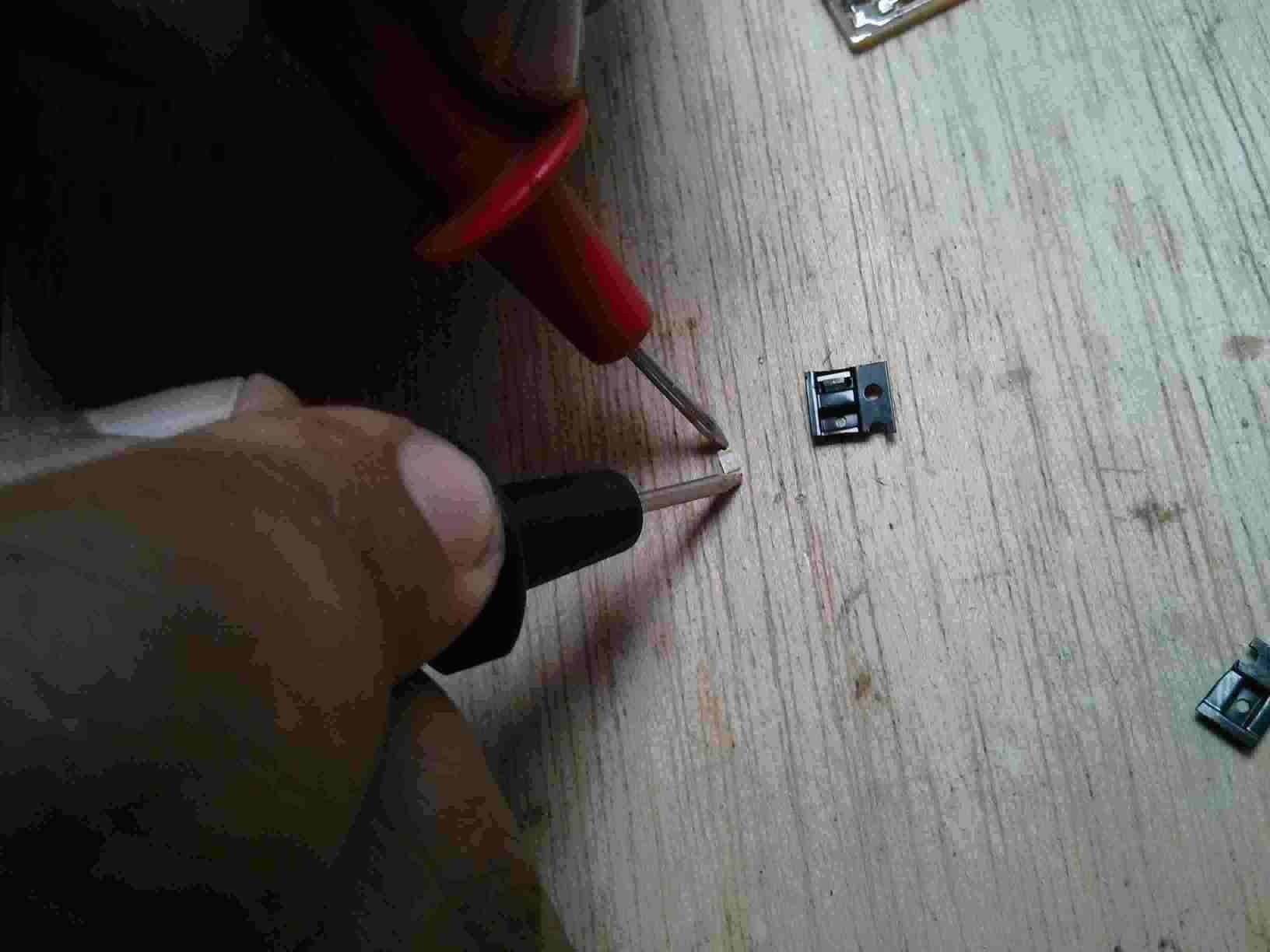
Testing the solder components.
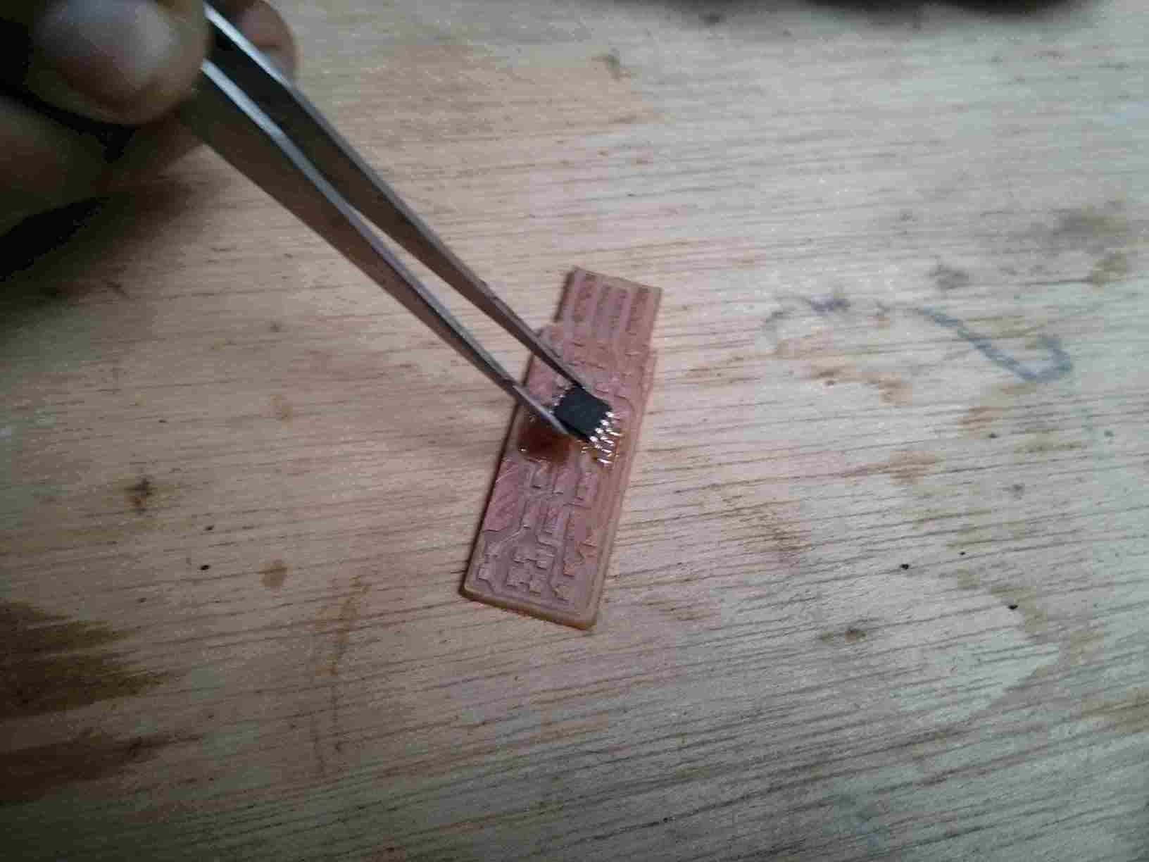
Testing soldering SMDs (Surface Mount Devices).
Placing solder on the board to set the MCU easily.
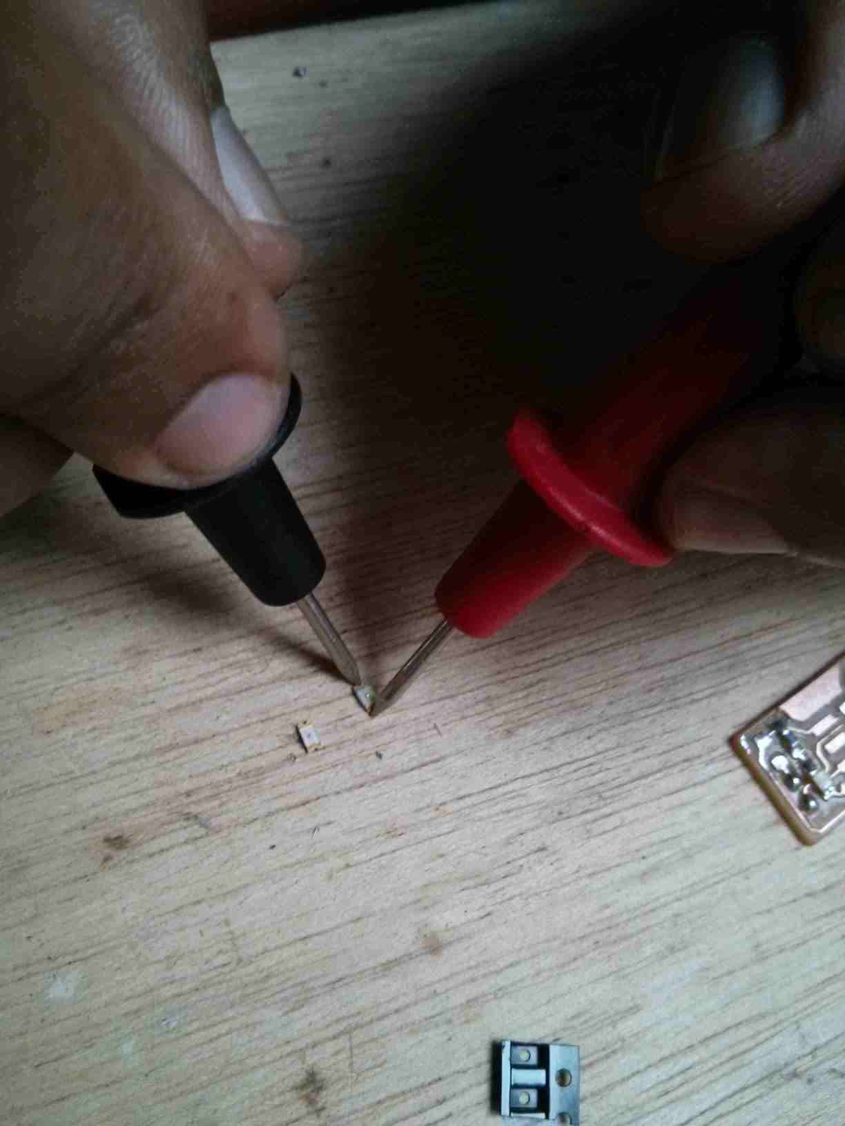
Testing the LEDs for color and polarity.
The soldered LEDs and resistor.
Soldered capacitor
Soldered resistor
Zenner
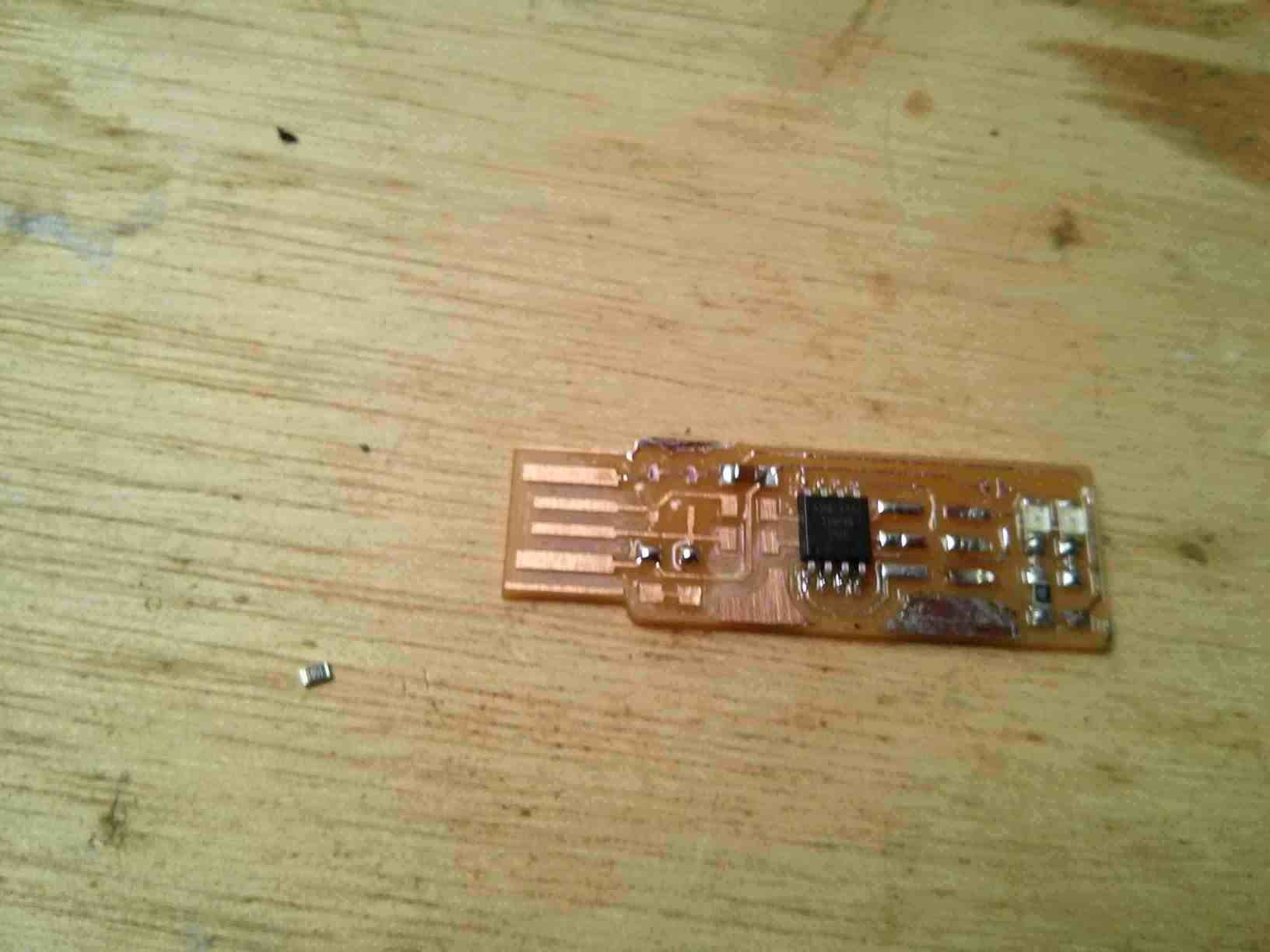
Other zenner. Notice it is too small to solder as designed.
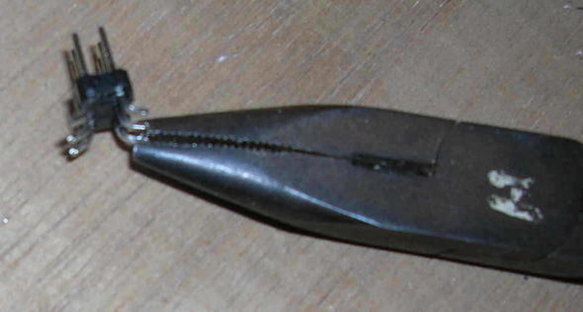
Bending the header legs.
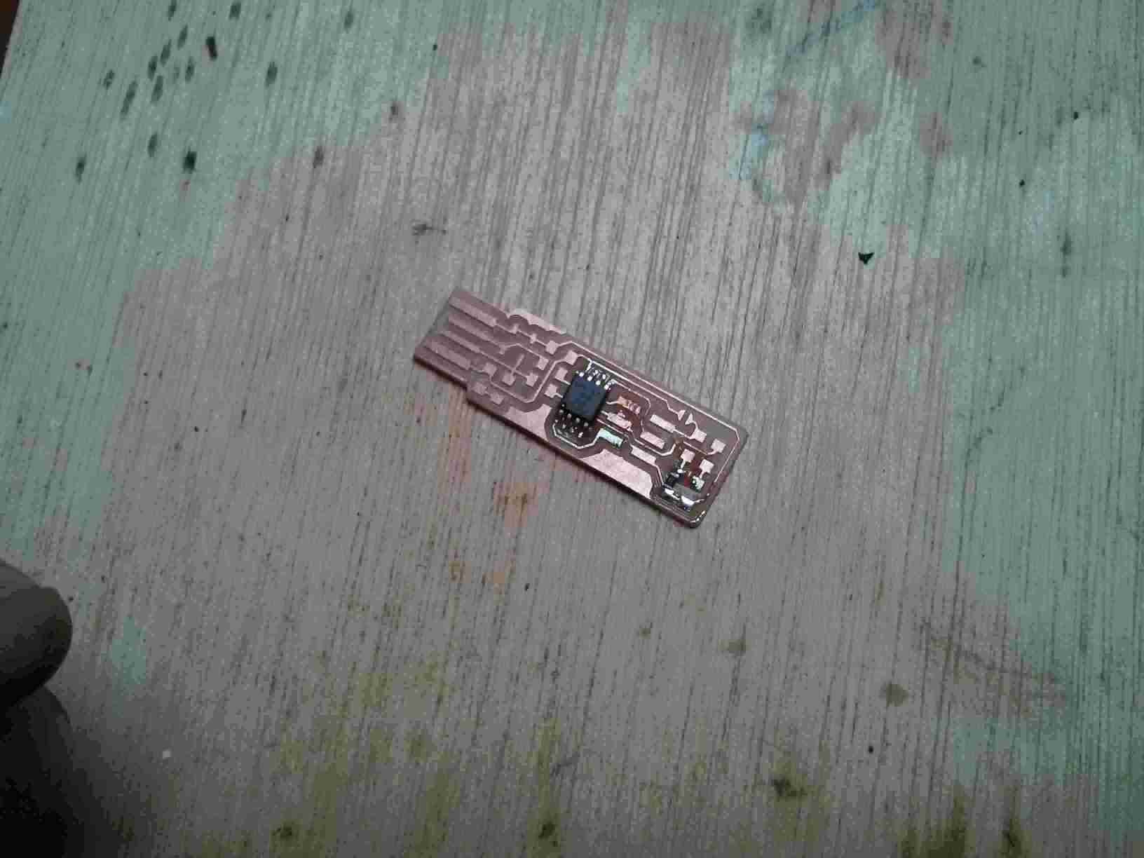
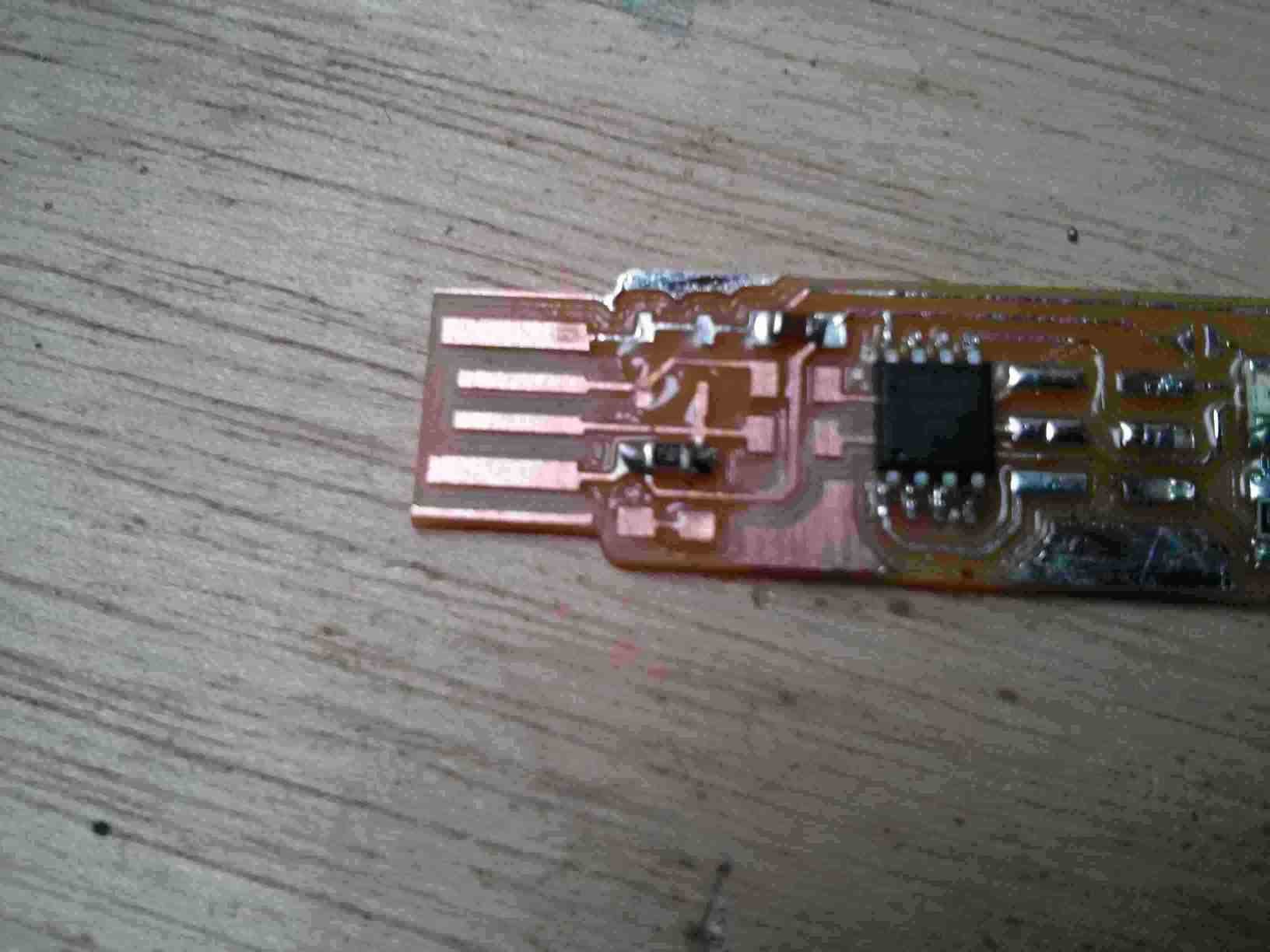
Soldering finished
Adding a glued piece of plastic to give the width needed for the USB bus connector.
Sanding the elevator piece.
The board USB connector now has a thickness to standard.
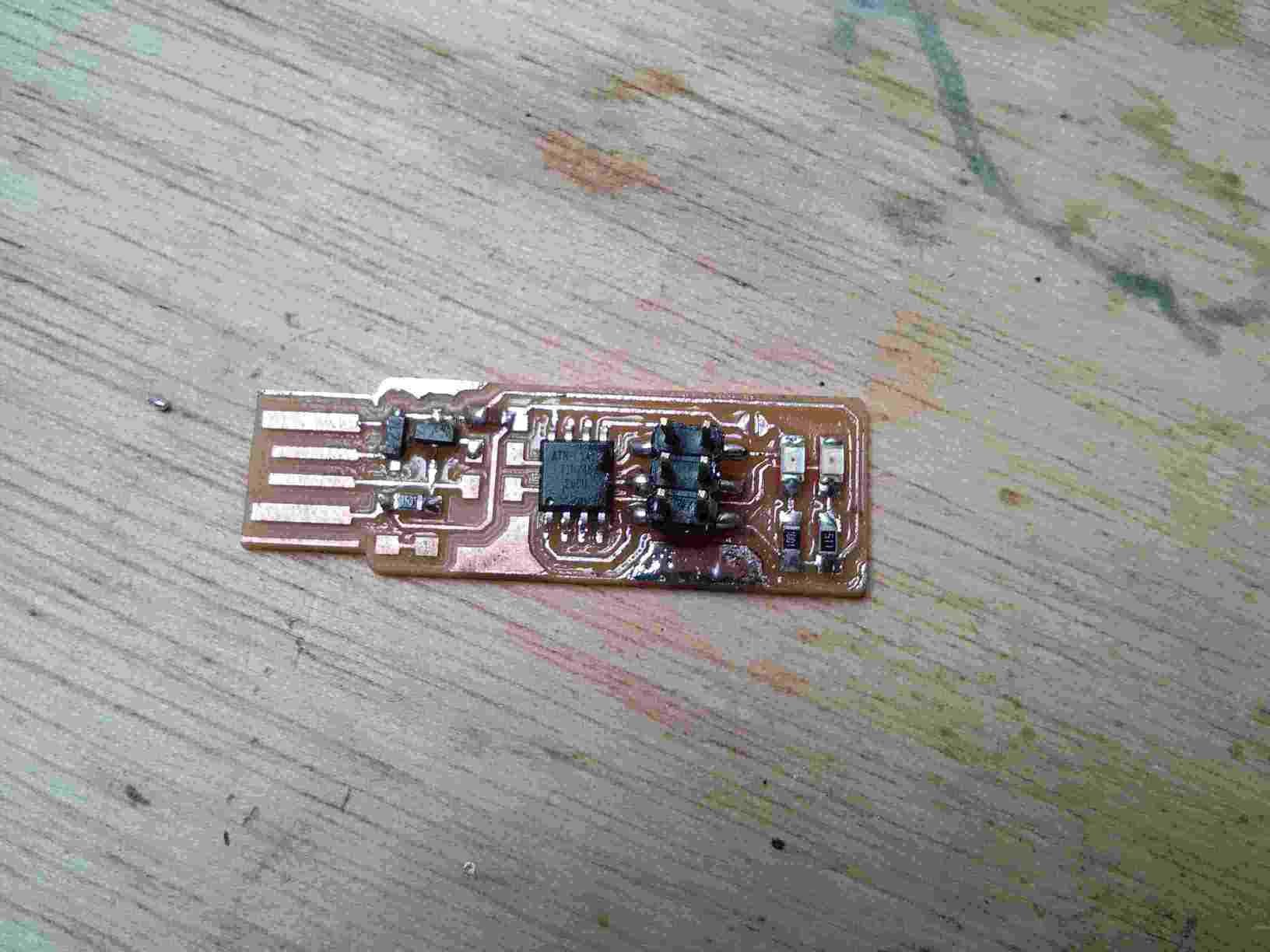
Cut the excess copper at the tip of the USB connector and added solder to the communication and power pads to make them gain volume.
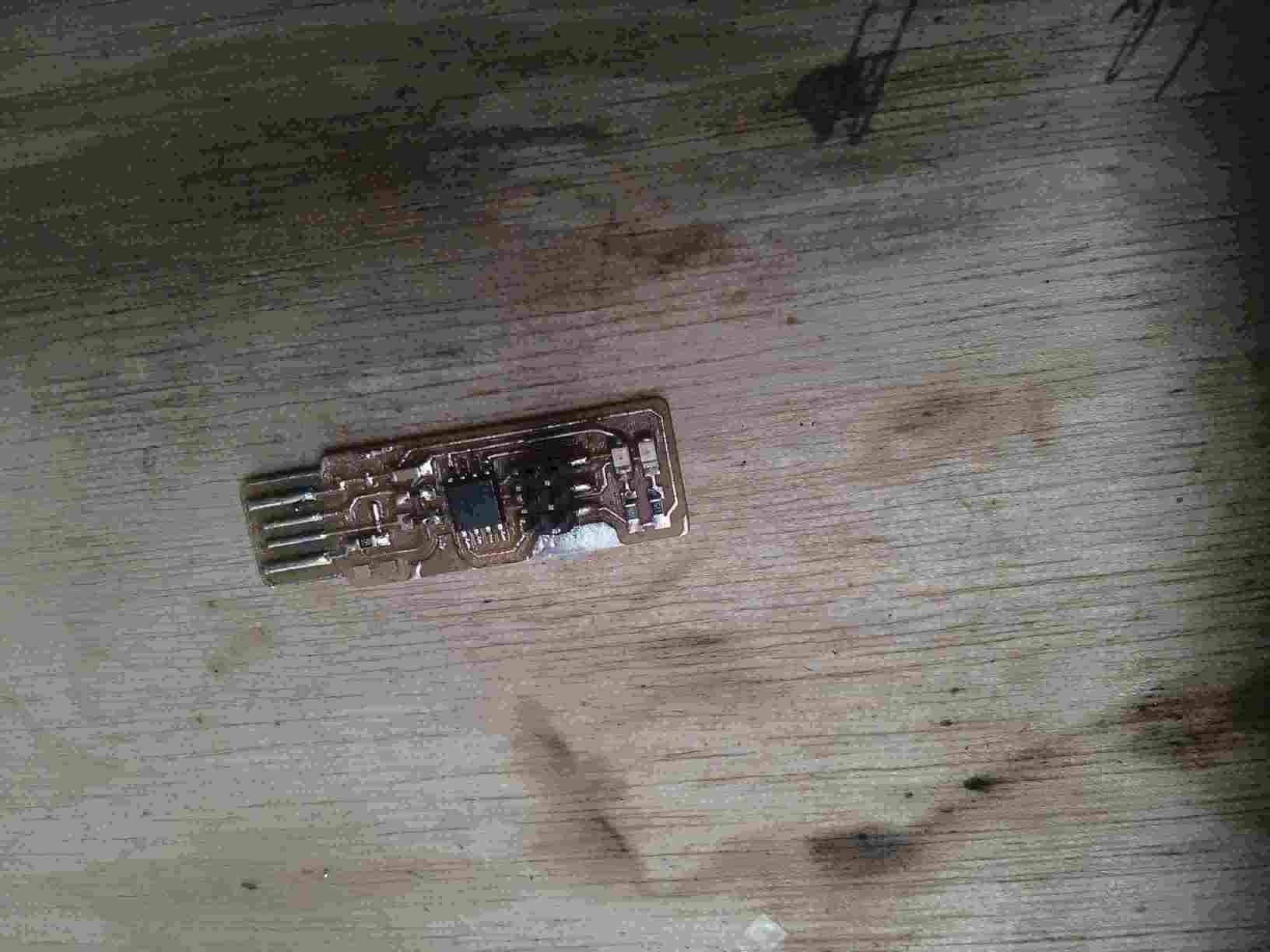
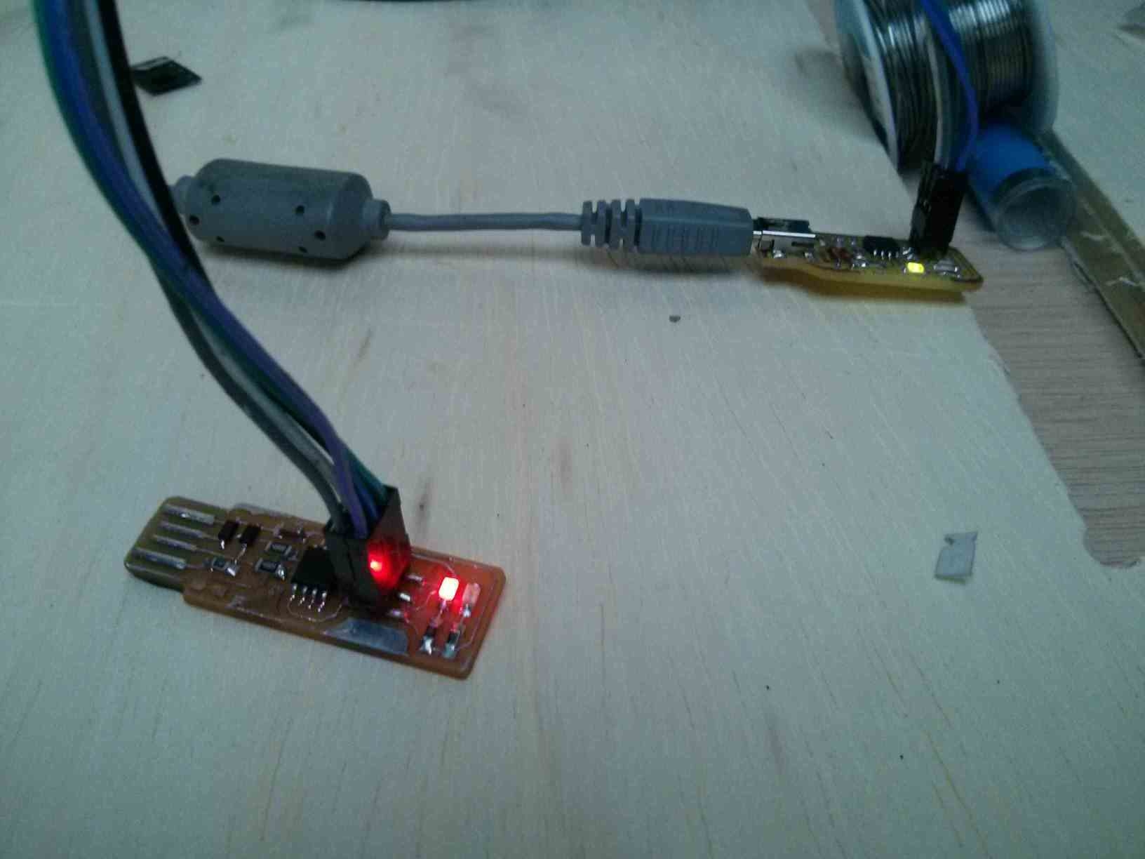
The light will not glow because the programmer's fuses have not been blow yet.
In order for the board to do anything, the MCU must have a program. In this case, the MCU must be able to program other boards. The appropriate program is then loaded.
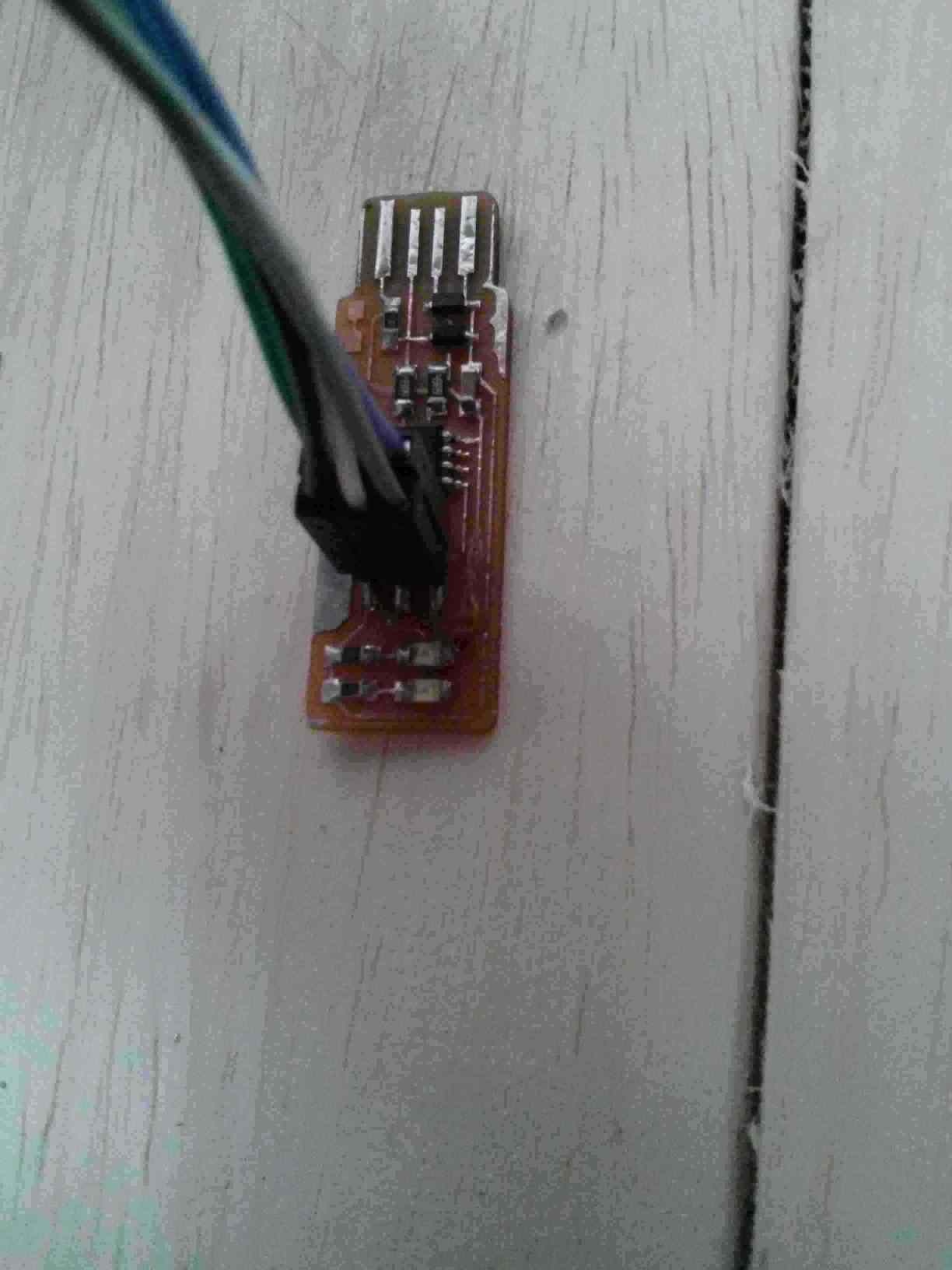
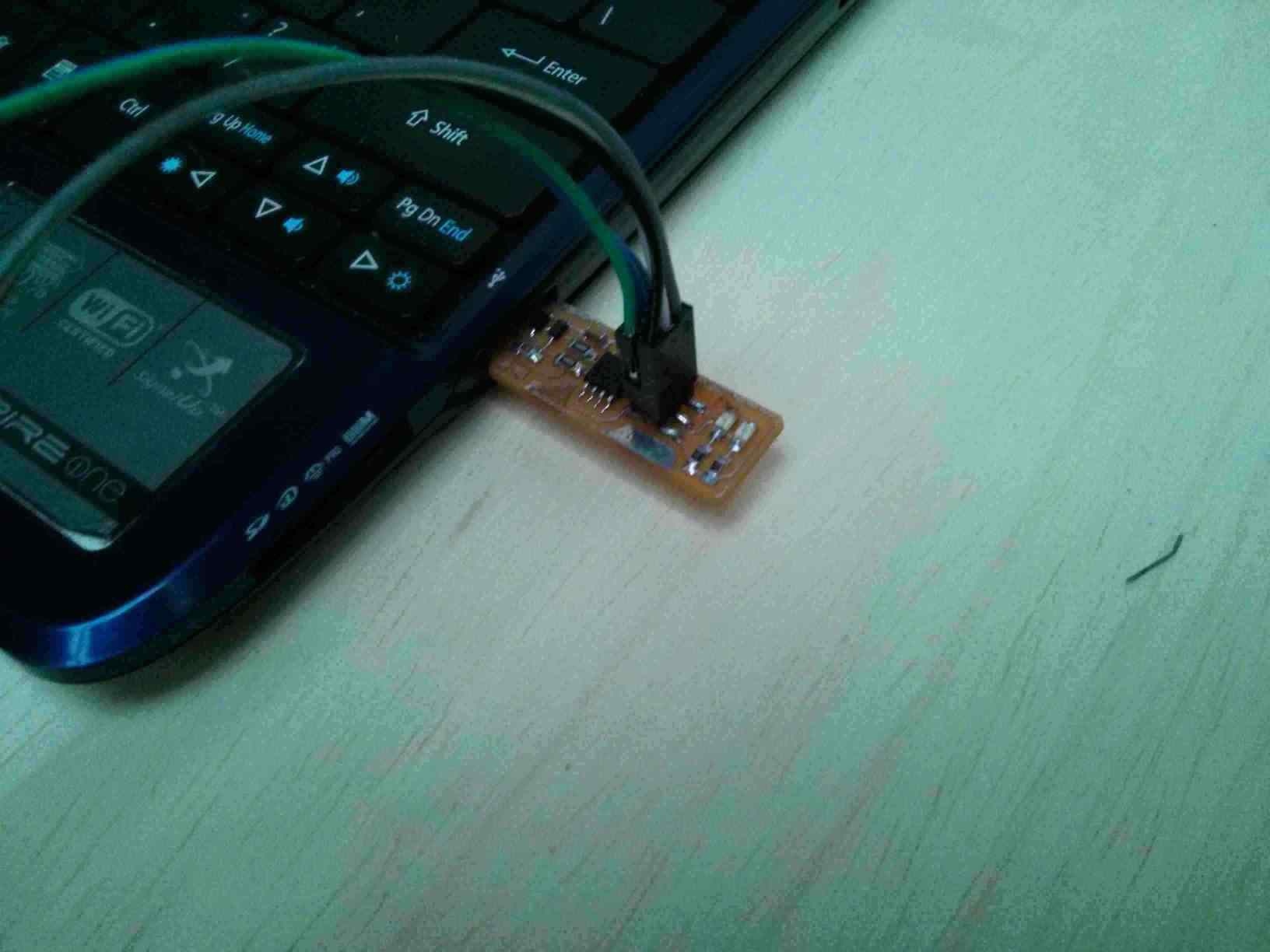
Connect a functional In-System Programmer to the new ISP through 2x6 header pins. Make sure each pin is on the same connection on both boards.
Connect the functional ISP to the computer USB port.
In order to program the FabTinyISP, I followed the instructions at http://fabacademy.org/2018/docs/FabAcademy-Tutorials/week4_electronic_production/fabtinyisp_english.html
The first thing I did was downloading and decompressing the firmware. Then I compiled with make.
make
make flash
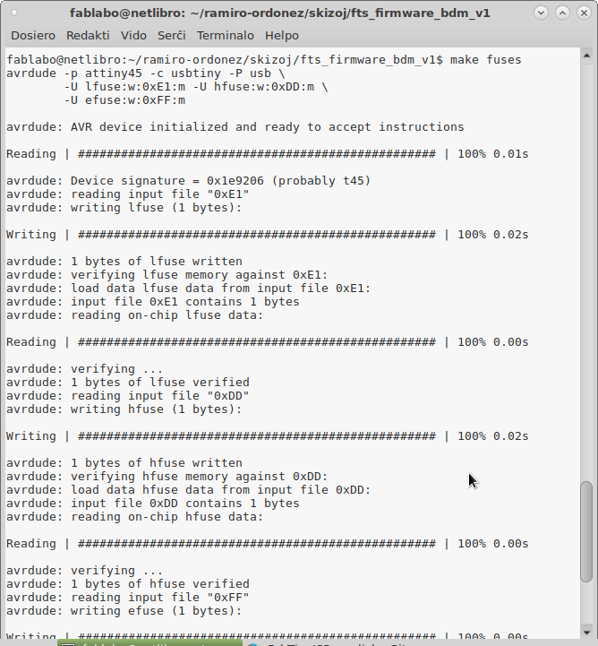
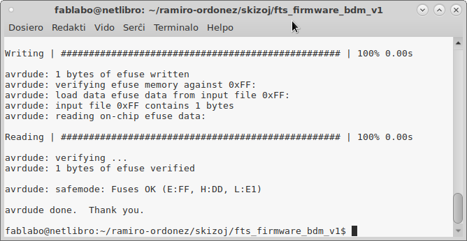
make fuses
make rstdisbl
Transfering the firmware to the new board gave these results:
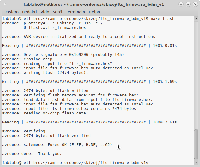
$ make flash avrdude -p attiny45 -c usbtiny -P usb -e \ -U flash:w:fts_firmware.hex avrdude: AVR device initialized and ready to accept instructions Reading | ################################################## | 100% 0.01s avrdude: Device signature = 0x1e9206 (probably t45) avrdude: erasing chip avrdude: reading input file "fts_firmware.hex" avrdude: input file fts_firmware.hex auto detected as Intel Hex avrdude: writing flash (2474 bytes): Writing | ################################################## | 100% 1.69s avrdude: 2474 bytes of flash written avrdude: verifying flash memory against fts_firmware.hex: avrdude: load data flash data from input file fts_firmware.hex: avrdude: input file fts_firmware.hex auto detected as Intel Hex avrdude: input file fts_firmware.hex contains 2474 bytes avrdude: reading on-chip flash data: Reading | ################################################## | 100% 2.65s avrdude: verifying ... avrdude: 2474 bytes of flash verified avrdude: safemode: Fuses OK (E:FF, H:DD, L:E1) avrdude done. Thank you.
So the device then is disconnected from the programmer and it is recognized by the usb port.
$ lsusb Bus 003 Device 012: ID 1781:0c9f Multiple Vendors USBtiny
I tried to reset the fuses without connecting the other board. I thought that it was already programmed and that it did not need the programmer any more. So I ran the command and had an error.
$ make rstdisbl avrdude -p attiny45 -c usbtiny -P usb \ -U lfuse:w:0xE1:m -U hfuse:w:0x5D:m \ -U efuse:w:0xFF:m avrdude: initialization failed, rc=-1 Double check connections and try again, or use -F to override this check. avrdude done. Thank you. Makefile:70: recipe for target 'rstdisbl' failed make: *** [rstdisbl] Error 1
I reconnected the old programmer and then it would work correctly.
$ make rstdisbl avrdude -p attiny45 -c usbtiny -P usb \ -U lfuse:w:0xE1:m -U hfuse:w:0x5D:m \ -U efuse:w:0xFF:m avrdude: AVR device initialized and ready to accept instructions Reading | ################################################## | 100% 0.01s avrdude: Device signature = 0x1e9206 (probably t45) avrdude: reading input file "0xE1" avrdude: writing lfuse (1 bytes): Writing | ################################################## | 100% 0.00s avrdude: 1 bytes of lfuse written avrdude: verifying lfuse memory against 0xE1: avrdude: load data lfuse data from input file 0xE1: avrdude: input file 0xE1 contains 1 bytes avrdude: reading on-chip lfuse data: Reading | ################################################## | 100% 0.00s avrdude: verifying ... avrdude: 1 bytes of lfuse verified avrdude: reading input file "0x5D" avrdude: writing hfuse (1 bytes): Writing | ################################################## | 100% 0.02s avrdude: 1 bytes of hfuse written avrdude: verifying hfuse memory against 0x5D: avrdude: load data hfuse data from input file 0x5D: avrdude: input file 0x5D contains 1 bytes avrdude: reading on-chip hfuse data: Reading | ################################################## | 100% 0.00s avrdude: verifying ... avrdude: 1 bytes of hfuse verified avrdude: reading input file "0xFF" avrdude: writing efuse (1 bytes): Writing | ################################################## | 100% 0.00s avrdude: 1 bytes of efuse written avrdude: verifying efuse memory against 0xFF: avrdude: load data efuse data from input file 0xFF: avrdude: input file 0xFF contains 1 bytes avrdude: reading on-chip efuse data: Reading | ################################################## | 100% 0.00s avrdude: verifying ... avrdude: 1 bytes of efuse verified avrdude: safemode: Fuses OK (E:FF, H:5D, L:E1) avrdude done. Thank you.
So now it is has programmed the new board and reset the disable bit.
So now I disconnected Vcc from the reset pin. But that caused the USBtinyISP to disconnect Vcc from the LEDS and from FTDI and SPI connectors. So I re-soldered the connection. This is apparently a flaw in the board design.
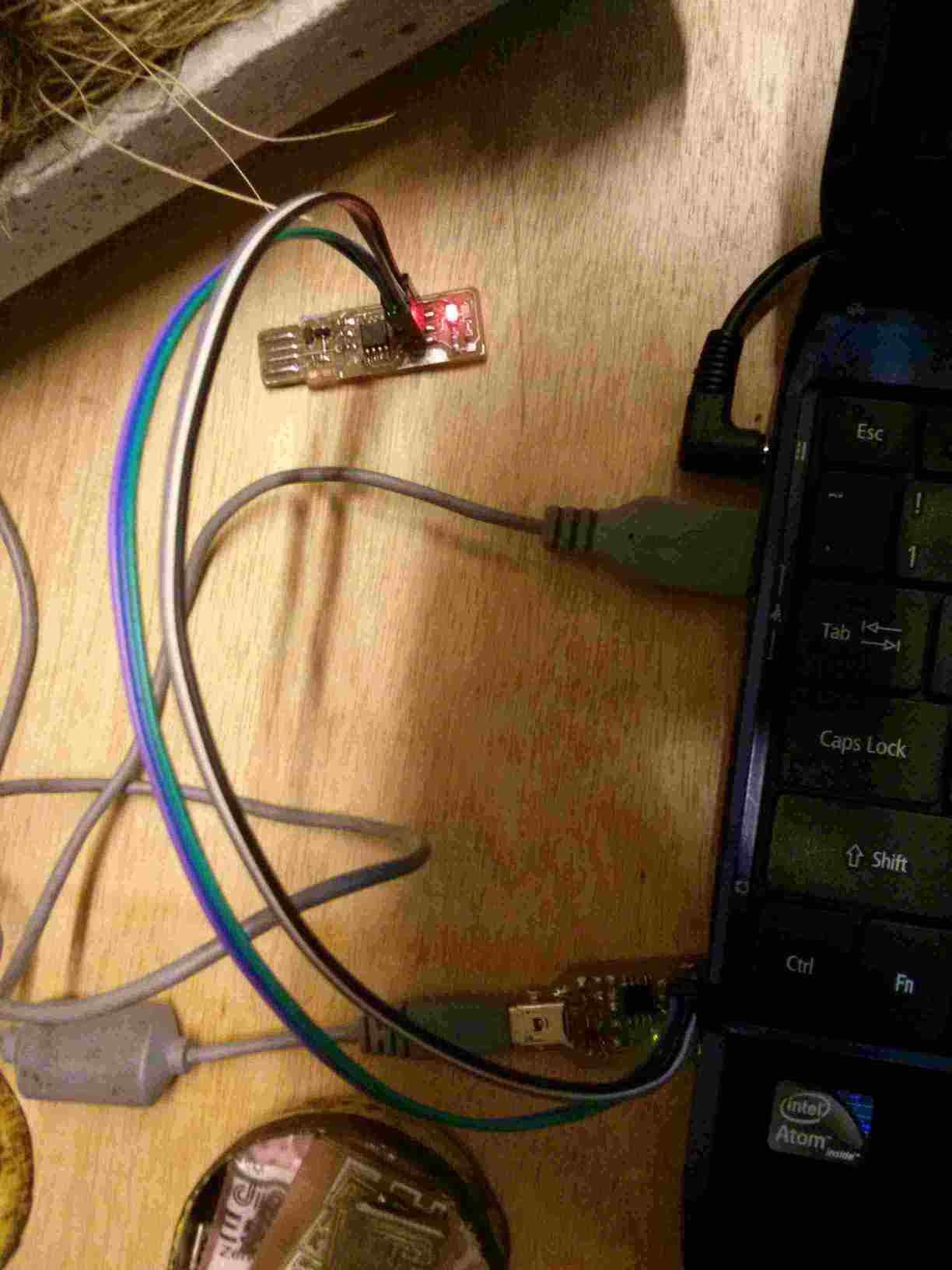
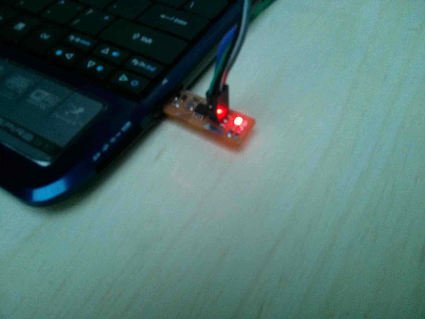
Now I get a glowing light when connecting the board to the computer's USB port.
Making an In-System Programmer is an easy process once you know how to do it. It is a very useful piece of hardware.
The inside and outside colors of image file for the traces must be considered carefully in order for FabModules to make correct Gcode files out of them. There must be color on both sides of the traces and cuts. If not, they will not be done correctly.
Soldering is difficult at first. But you can start with larger package parts for startup ease. I have a trembling problem. But it was still possible for me to solder. Nevertheless, at first it took help and many hours of failure before acquiring the minimum necessary skill.
Care must be taken to work with sharp and hot tools. I cut myself with the bit and burned myself with the hot soldering stencil. They were not severe injuries. But they could be even deadly and it would be better to avoid these hazards.
Autoleveling of the table and a good quality end-mill are very important to get good PCB boards.
It is easier to use a very pointy (10°) end-mill for both milling and cutting. Then you do not waste time in changing end-mills.