Materials, tools and software
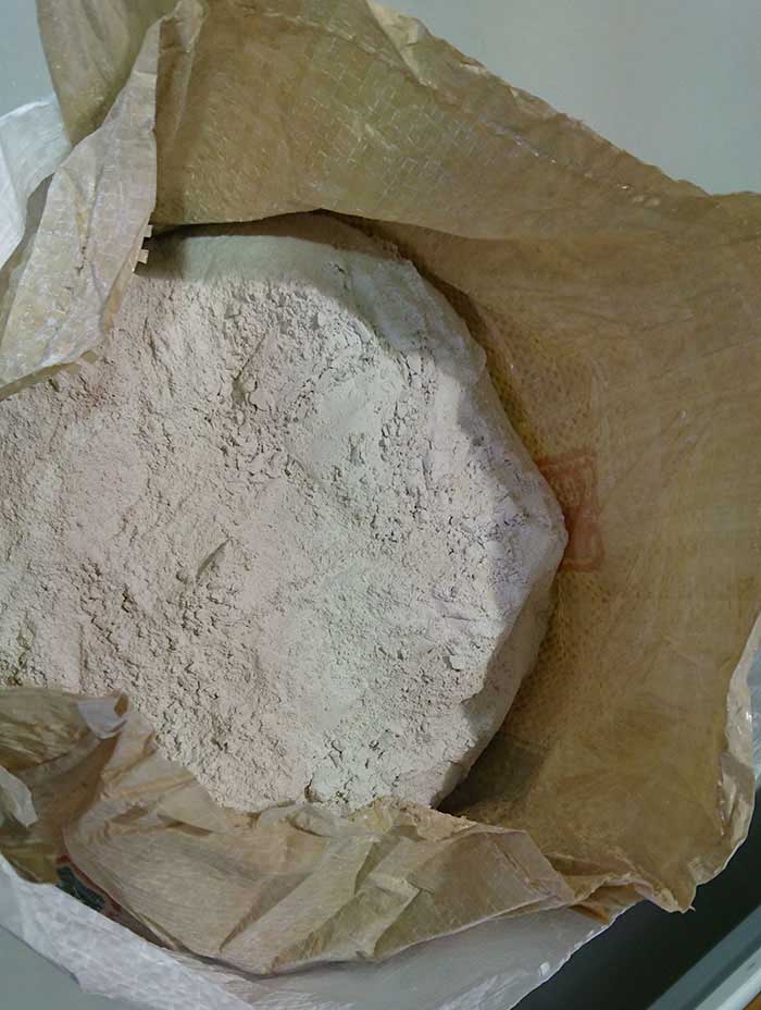
Plaster (Materials)
Water (Materials)
Shopbot (Tools)
Fabtotum (Tools)
Solidworks (software)
Fusion 360 (software)
 |
 |
 |
 |
|---|
Plaster (Materials)
Water (Materials)
Shopbot (Tools)
Fabtotum (Tools)
Solidworks (software)
Fusion 360 (software)
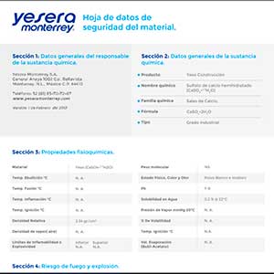
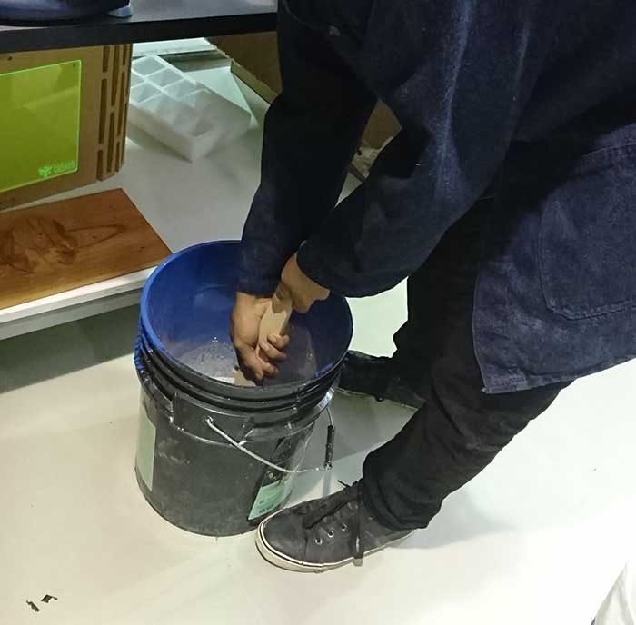
For this assignment we analyze two materials, a mineral that we buy in powder which generates a reaction with the
water hardening the material, currently a very used method in the crafts to develop matrices or molds.
Below you can find the datasheet to know more about this material.
Other materials used this week is polyester resin and silicon rubber two composite materials which work in similar
ways the difference is in their properties, the resin in contact with its drying compound will be rigid and the rubber
will otherwise be flexible, for this reason they are very good tools for the development of the following exercise.
Below we can find the links for the datasheet of each of the materials
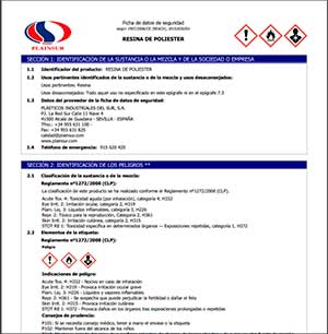
It is a thermosetting unsaturated polymer, which is formed from the reaction between organic acids and polyhydric alcohols. They are also known as condensation polymers. In said reaction, the by-products are liquids, including water or methanol.
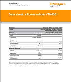
It is a derivative of quartz rock combined at high temperatures with carbon. From this base, various physical forms such as gel, oil and solid can be obtained.
This material gives us versatility and excellent behavior in various physical and chemical environments, and can be transformed into multiple production
processes such as injection, compression molding, extrusion, autoclave, casting, etc.
It also has a wide variety of uses within which we can detail the following Pharmaceutical, chemical, medical, aeronautical, space, laboratories, food,
cosmetics, Packaging, packaging, fluids, metalworking, construction, lighting, electronics, automotive, machinery in general, etc.
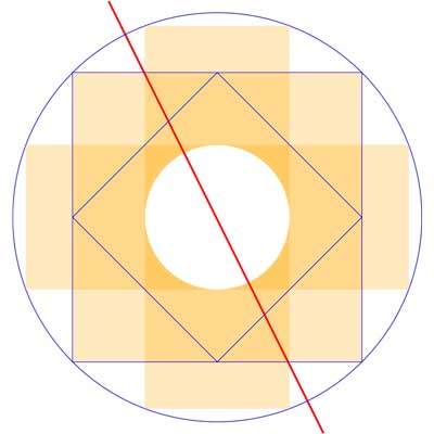
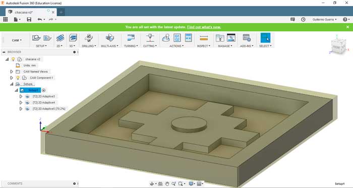
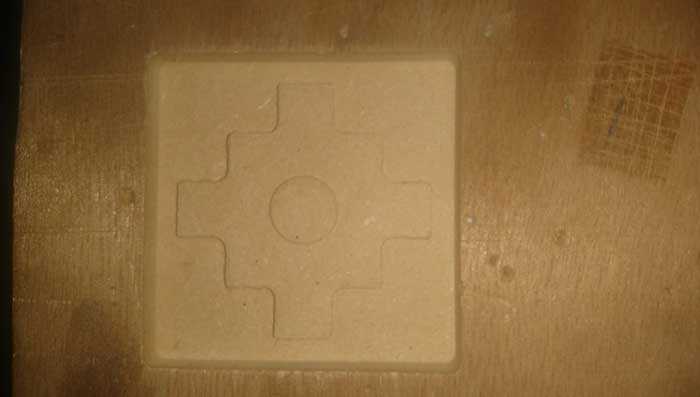
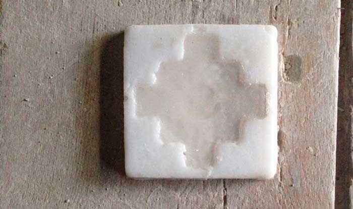
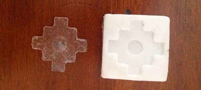
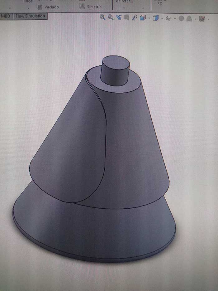
For this process use Fusion 360 for the design and machining process, for the design I chose a pre-Columbian design the main ico of the Andean cosmobition the "chacha" or Andean cross.
For the design in fusion 360 was made by different levels use tools of basic design to generate this form the main geometrical figures the tool
of rectangle and circle.
First we create the proportion for the development of the cross based on the rectangle we create the cross and we give it the first level.
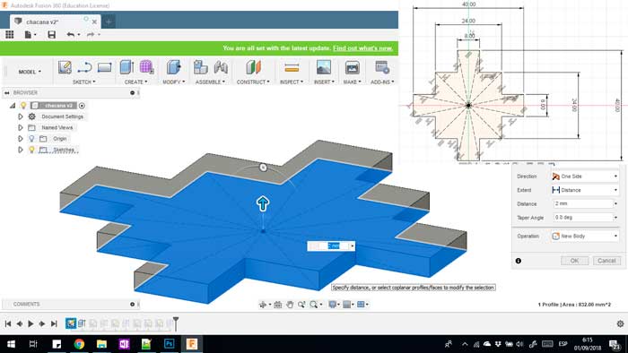
second stage design the circle in the center of the cross and in the same way we extrude it
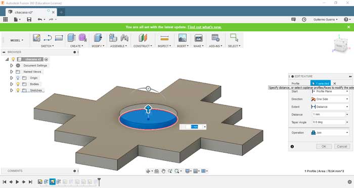
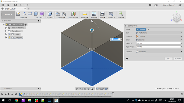
Once these processes are finished, we create the space that will serve to contain the material that we are going to pour.
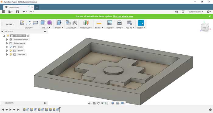
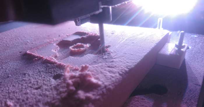
The next step in the development is the CAM process for this I create a new configuration in SETUP in which we modified the frames of the pieces to be machined, choosing the correct orientation of the axes according to the point of origin selected and that of the machine.
now we choose the process that will take place for the machining for this case I use 2D processes the 2D ADAPTIVE CLEARING tool for which we only have to choose the milling to be used with their respective characteristics in this case one of two flutes at 13000 rpm and 200 mm / min your feedrate
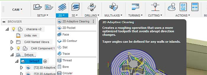
now we choose the process that will take place for the machining for this case I use 2D processes the 2D ADAPTIVE CLEARING tool for which we only have to choose the milling to be used with their respective characteristics in this case one of two flutes at 13000 rpm and 200 mm / min your feedrate
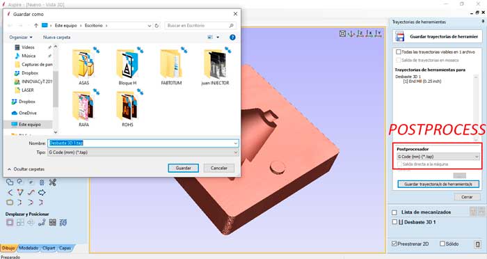
To finish the process in Fuision 360 we generate the G code to load the program into the machine. For this we click on the tool "POST PROCESS".
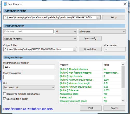
The G code obtained in Fusion is imported into the FAB TOTUM to be able to machine.
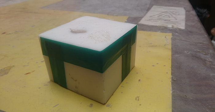
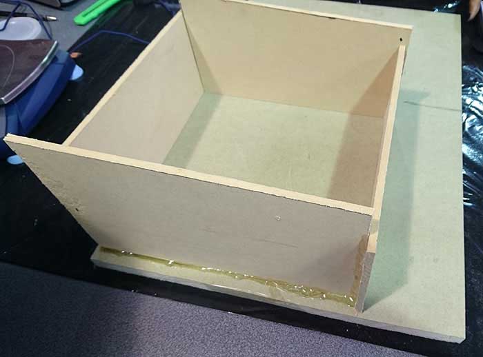
The mold was made in MDF which was then made a series of steps so that the other materials do not stick.
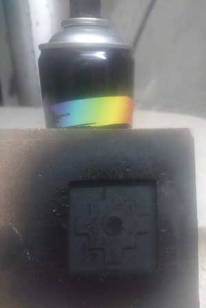
We paint with spray paint as it is enamel paint which creates a layer that isolates the wood preventing it from absorbing the material and sticking together, this same step we repeat with white rubber to have a second layer of protection .
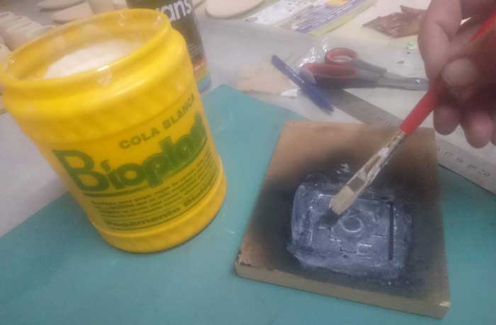
Before proceeding to create the mold we must take into account the measures of safety and protection of odors and isolate the hands or any part of the body from contact with these materials. as well as the gases, odors that emanate the materials when generating their chemical reaction take the necessary precautions.
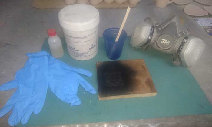
When it has dried everything we pour the cilicon rubber so that it creates the mold to be able to obtain the piece.
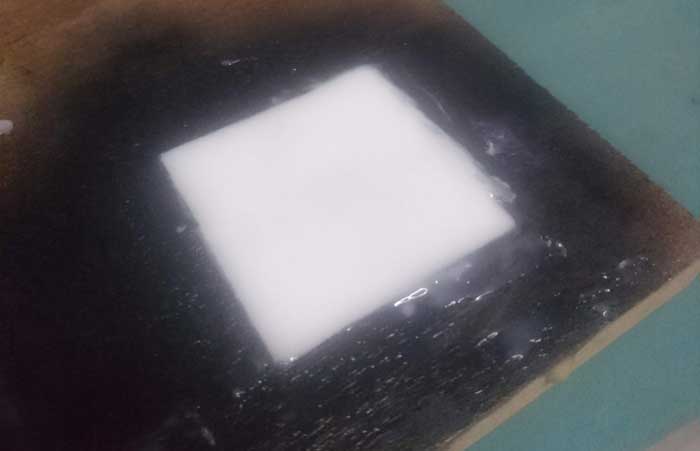
Once this also dry we can extract without any problem

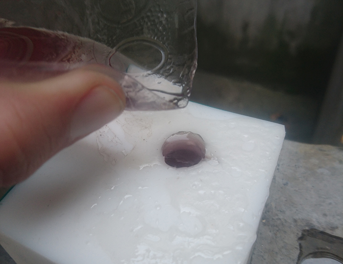
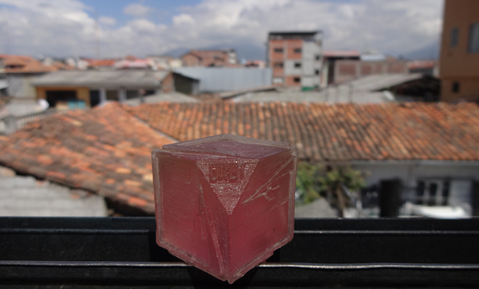
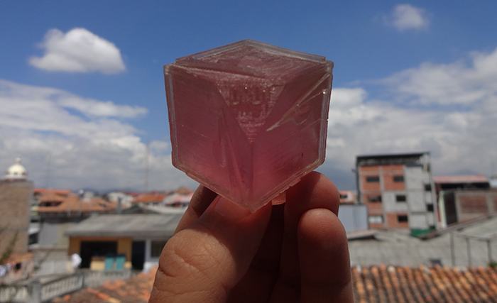
To obtain the final piece we will pour polyester resin so that it takes the shape of the mold.
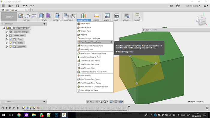
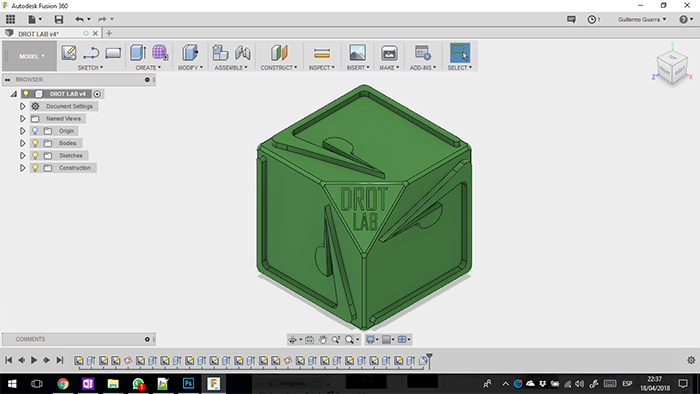
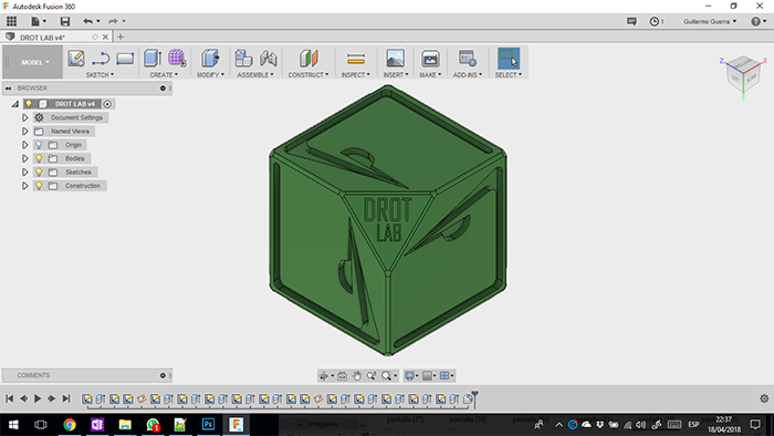
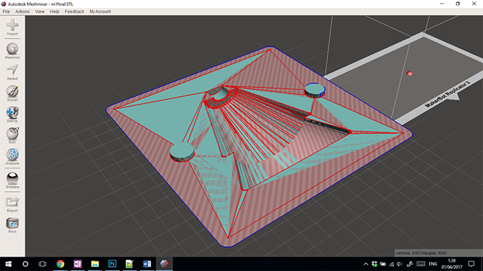
For the process of creation of the matrix, a cube was made on which the three-dimensional recreation of the logo was made, for which on one hand we worked in high relief and on the other in low relief, in this way its recreation in 3D printing was simplified. This model would be complex to replicate in the common technique of CNC machining.
Once the cube is created, we proceed to the creation of the planes based on three points, with which we can generate the respective cuts.
In order to obtain the following definitions of the piece we create in each of the planes to create the high relief.
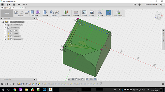
Use a similar process to generate the low relief process
For the machining we import the piece in STL format with which we will export in Cura to obtain the file to load in the machine.
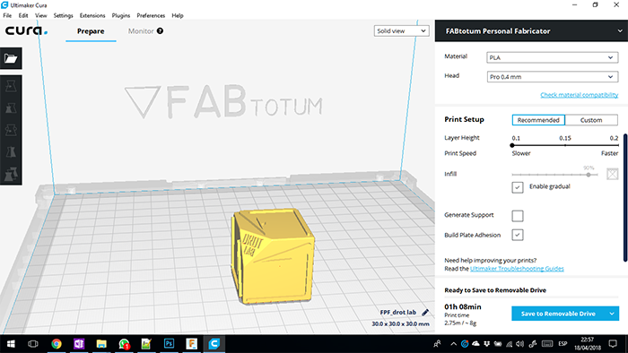
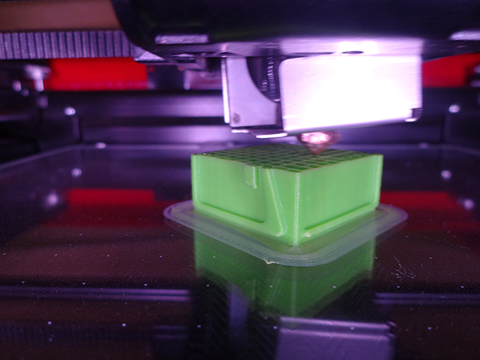
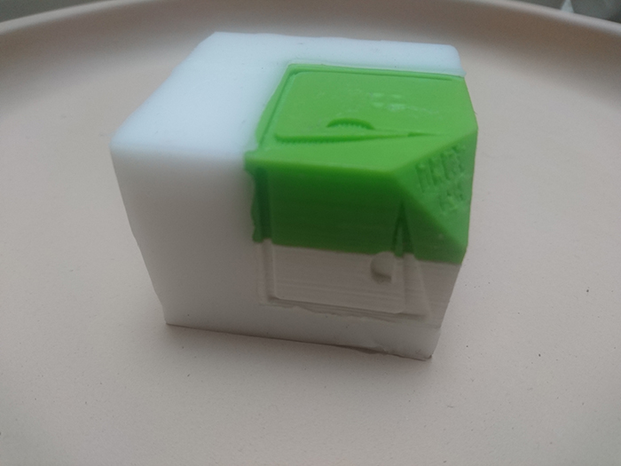
We load the file into the machine and proceed to print it
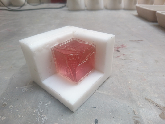
For the development of the molds we use acrylic to create the walls of the mold and that the rubber can be detached easily.
Due to the complexity of the piece, the mold was made in two lids in order not to retain the piece as explained below.
Once the sections are established, we place the base in order to pour the rubber for the creation of the piece, we generate the same process for the second face of the mold.
To obtain the figure we introduce polyester resin with its secante which will adopt the figure of the mold and let it generate reaction, harden and extract the piece.
To begin, I use this assignment to change the production in our ceramic workshop.
The first production process in the workshop is design the piece for make a molding and casting process. (All process is hand make)
The change in the process. I use the CAD CAM process to make the design of the piece and this take to make the mold in the shopbot.
In solidworks make the piece and take all measurements for the mold
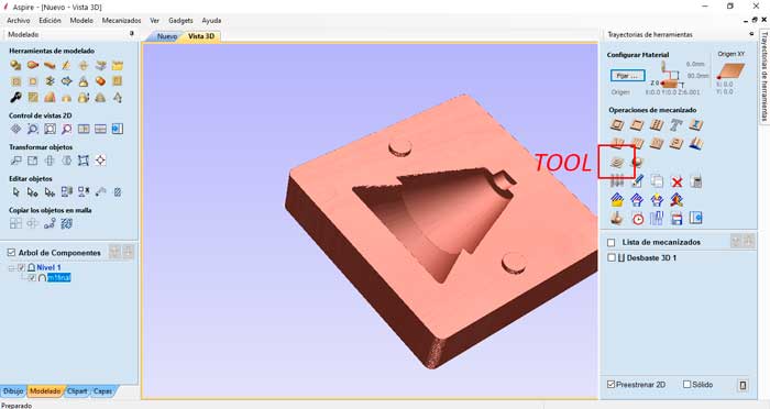
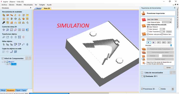
For the development of the 3D machining process Use the ASPIRE program, a versatile and very intuitive software that allows us to easily generate a process inside according to our requirements, for this case a three-dimensional model.
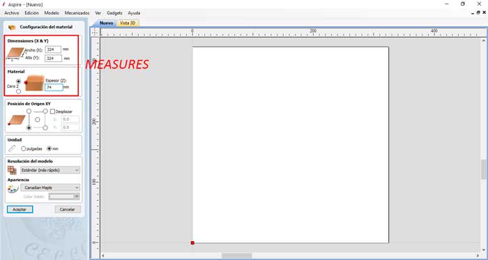
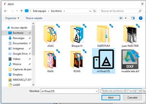
As a first step we will import the file for this, we will export the model in STL format. Once we have this file, we open the software and configure the measurements of our model.
When the file is loaded in the software, we proceed to choose the right tool to perform the necessary processes until we have the finish that we like or that meets our needs, in this process we will select the operation of WEATHER TOOL PATH IN 3D
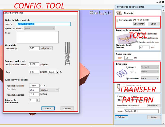
Once the process is selected, we will go to its configuration as the first point, we will select the most appropriate type of tool for the process in this case, a 1/4 inch roughing tool was chosen with which we can speed up the machining in the same way We choose the configurations such as travel speeds and the number of times in which the file will be divided to fulfill its final process. As well as we can configure the transfer pattern that we can see that is the most appropriate according to our piece.
Once completely configured, the configurations and the program are calculated by not sending a virtual route trace through which the machine program on the material complied, also in the way of a simulation in which we will be able to know what the behavior of the machinery will be.
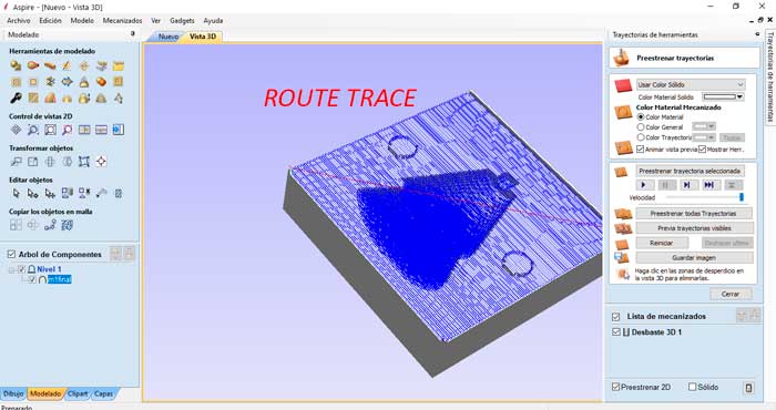
Once completely configured, the configurations and the program are calculated by not sending a virtual route trace through which the machine program on the material complied, also in the way of a simulation in which we will be able to know what the behavior of the machinery will be.
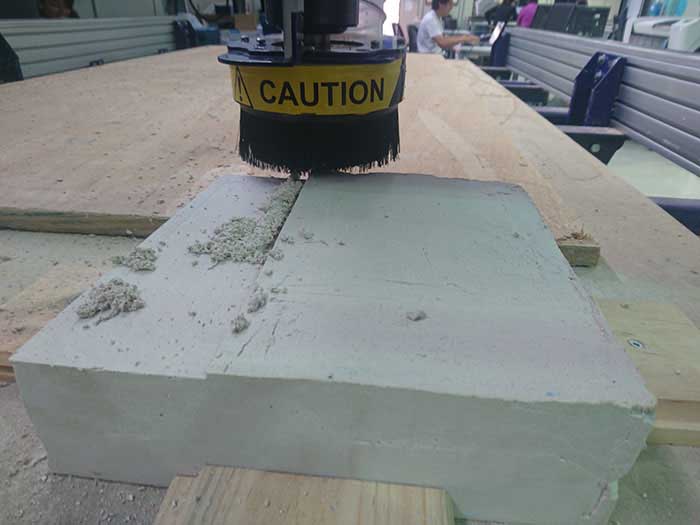
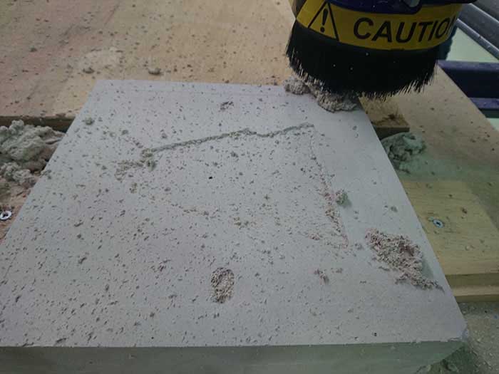
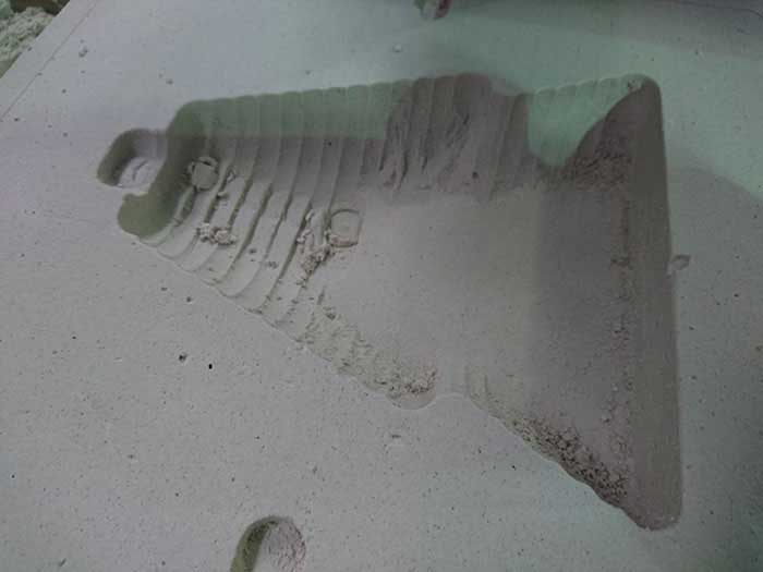
For the preparation. I calculate the volume of the block of the plaster in ceramic
For a problem with the schedule of the machine we can`t finish but we can make the first file in the machine with is a experimentation with the material.
For a problem with the schedule of the machine we can`t finish but we can make the first file in the
machine with is a experimentation with the material.
To finish this, I can make the mold to make the prototype in ceramic process.
In this assignment, I do this experimentation to apply to my ceramic workshop, this form I delete the
matrix of the production process and decreases one week the time of production line.
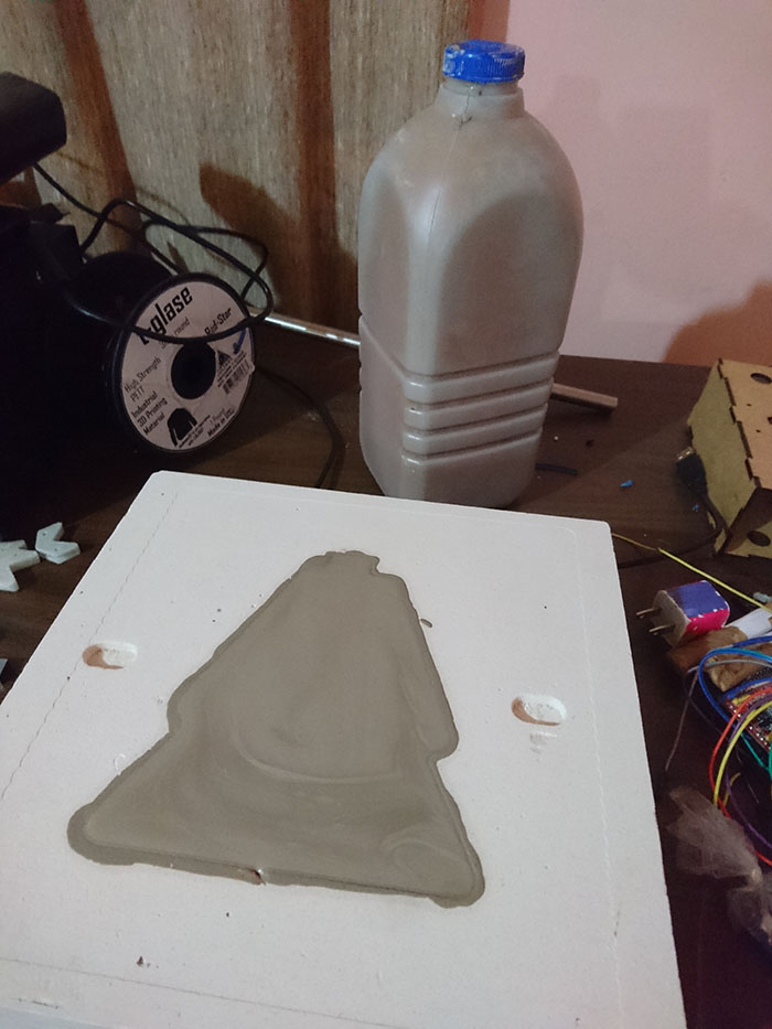
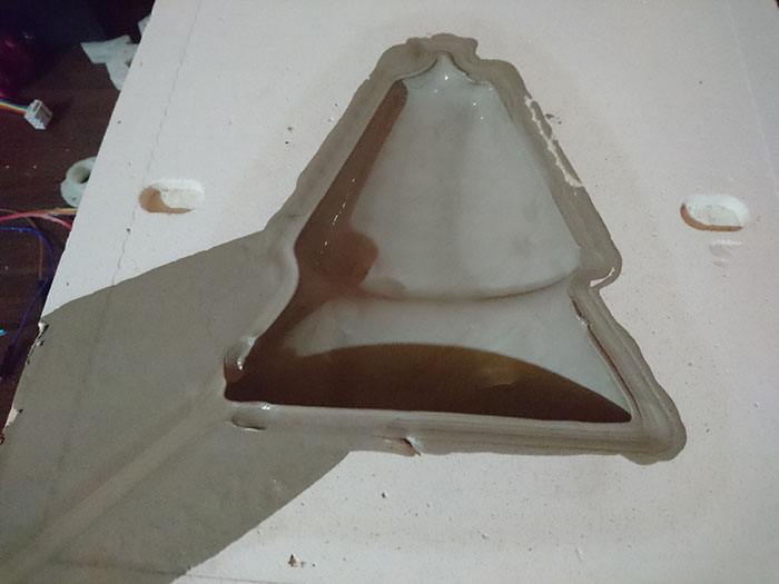
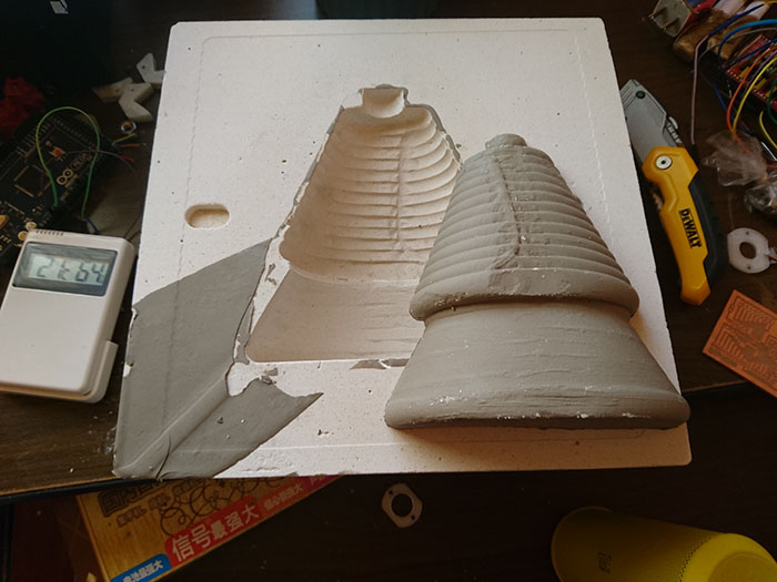
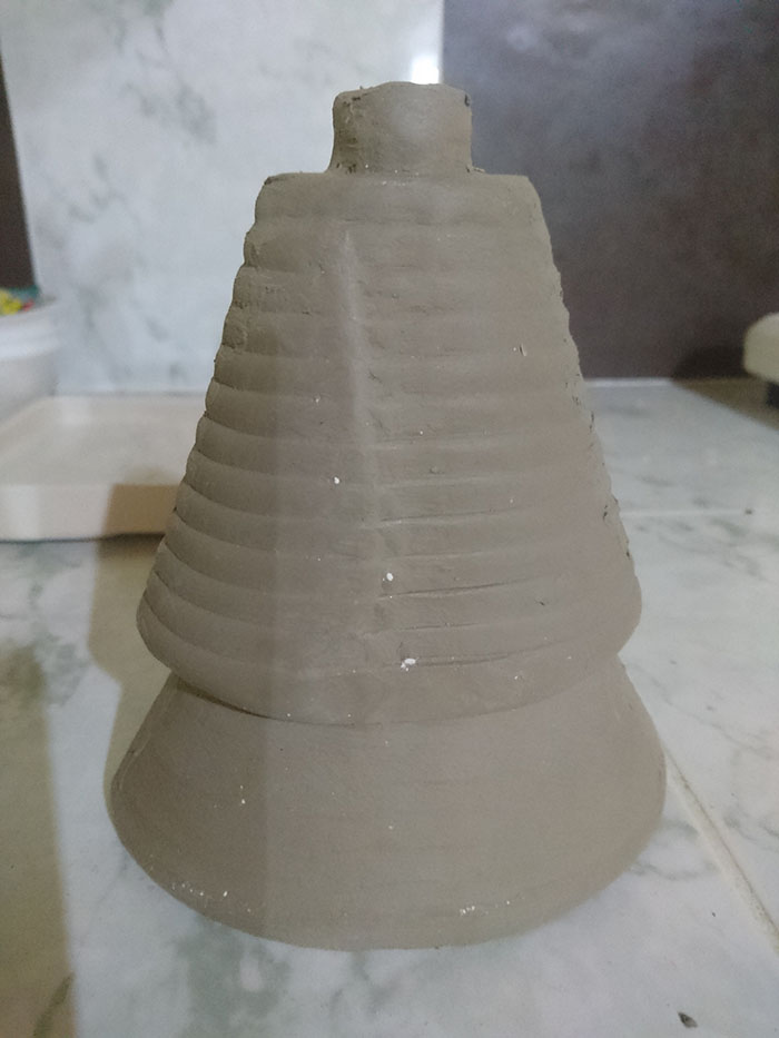
To make the clay production, I put the material in the mold and control because the mold absorbs the water of the material and the ceramic take the form of the mold when do you take the correct thickness extract the piece formed. I make two pieces and join to form the total piece.
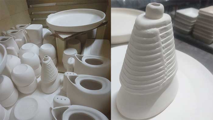
The next step in our workshop is to make a first burning of the pieces and we were able to burn a first piece of these. Then you can see the ovens that we have in our ceramic workshop.
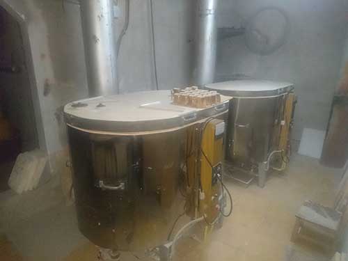
The burning process is done at 1000 degrees in the following image can observe the burned piece.