Materials, tools and software
Epilog Zing 24 (Tools)
Cameo (Tools)
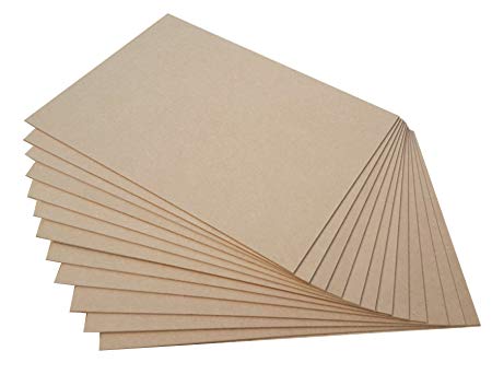
MDF 3mm (Materials)
Autocad (Software)
Solidworks (Software)
llustrator (Software)
 |
 |
 |
 |
|---|
Epilog Zing 24 (Tools)
Cameo (Tools)
MDF 3mm (Materials)
Autocad (Software)
Solidworks (Software)
llustrator (Software)
In the first part the group designed a piece for determine all size of the press fit for the application in the different projects of the week.
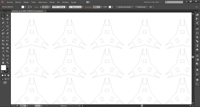
For the Design we use ILLUSTRATOR in which we analyze the ease of experimenting with this software for the laser cutting process.
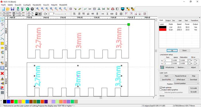
Within this process we made a piece to make the PRESS FIT tests on the material in this case 3mm MDF.
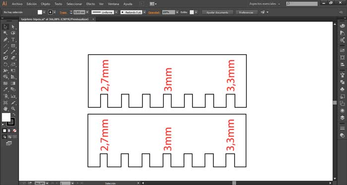
For the creation of the design, simple processes are developed in the creation of a figure with variations of measurements with which its behavior
can be checked to choose the appropriate one.
As you can see in the image the measurements of the assemblies vary from the basic measurement that we will find it in the center for the left it
is reduced 0.1mm and for the right side it increases 0.1mm
For the cutting of this piece we used a bodo laser cutter which uses the RDWORKS program a very simple software to manage once we have the complete design exported in the root format of the AI program which supports it without any errors as well as files DWG and DXF.
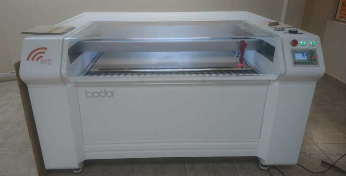
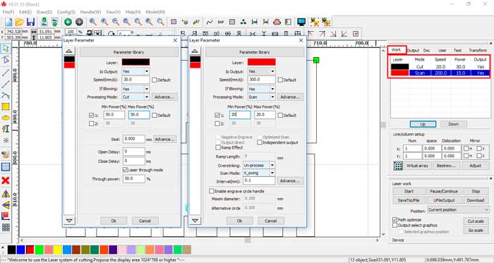
In the RDWORKS software, more than being able to visualize the files for machining allows us to create, modify, add and configure the parameters of the machine.
We make the communication between the program and the machine by connecting the USB cable or by wifi and establish the communication in the software.
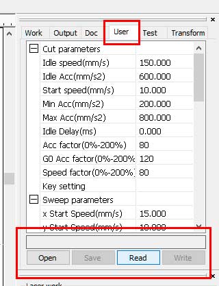
To send the file to the machine in the right window we have the USER button, we click on the READ button with which the software is linked to the
machine. We send the configurations from the computer to the machine.
Sent the command the machine will comply with the cut code in the material with the power and the speed specified in the software to cut 3mm MDF we
use a chromatic interpretation:
--Black: Cut with a speed setting of 30 mm per second, with a power of 50%.
--Red: Recorded with a speed setting of 300 mm per second, with a power of 20%.
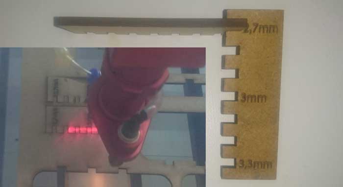
Once the command has been sent, the machine will complete the machining. Several tests were carried out to choose the appropriate measurement for the
different designs that we can generate. As final assembly we could choose between 2.7 mm since its pressure fit is applied firmly for joining pieces.
With this we can make our designs based on this contraction to make pressure assemblies in consideration of these measures.
I make the design in two different software:
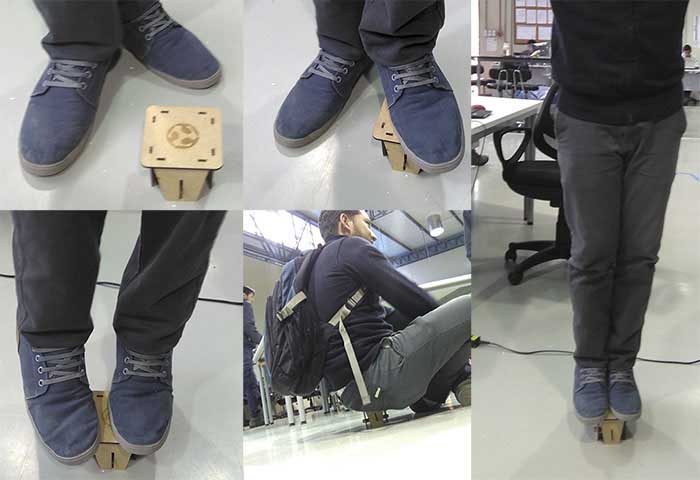
With design the new project I take ergonomic measures and make a bidimensional object with press fit, make a scale model in the cutting laser.
I did resistance tests.
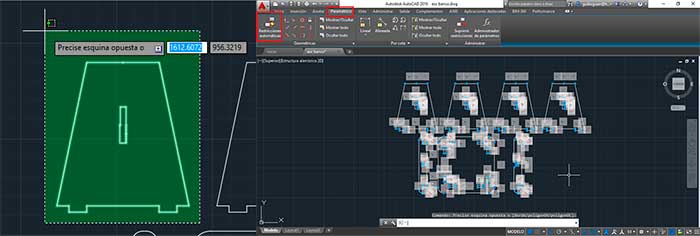
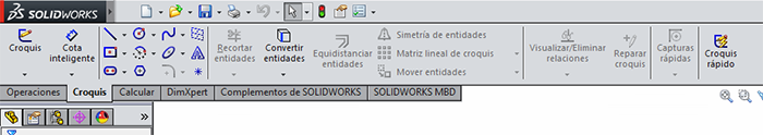
To perform the parameterization process in the Software is a very simple process once the modeling is done, we go to the "PARAMETRIC" tab and
select the objects with right click and select the objects separately for each one and choose the tool " AUTOMATIC RESTRICTIONS ".
Also in the following link you can find other ways to make parametrization in the design process.
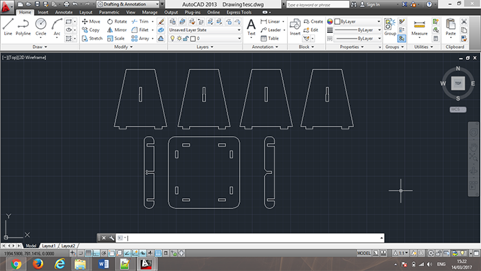
For the design in AutoCAD 2D tools were used to generate the figure inside the main element with the line tool to create the outline of our figure.
The use of this tool in AutoCAD is used based on the dimensions and measurements on the desired measures for the design of ergonomic, anthropometric
tools.
The following tools to generate a two-dimensional drawing were the arch and Fillet tools for the curved parts of the files.
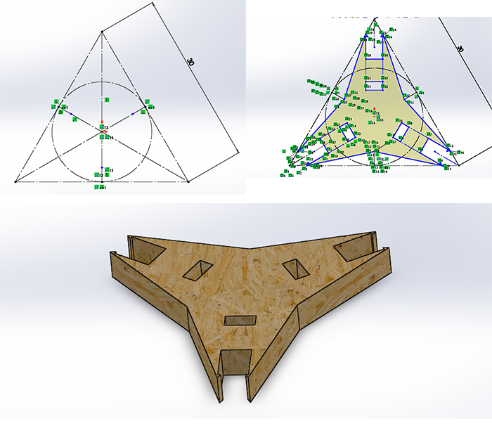
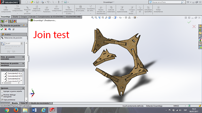
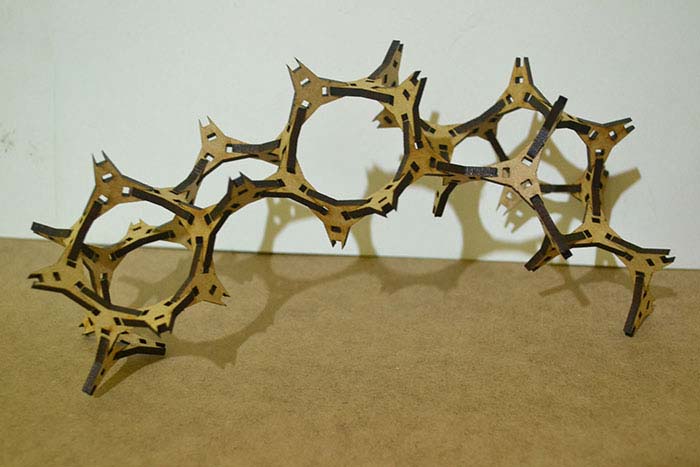
I design a prototype for the stand of FAB LAT in Chile for Fab13.
This prototype is a modular piece but this join can make any position and different alternatives of this pieces.
To make this piece, I use solidworks in 2D design, I make a simulation of the join test and I import to PDF to
make the test of the size of the pieces.
To model the piece I create a plane and use the 2D tools like line, polygon, trim. Draw the sketch with the different tools of 2D; see more information about this software in the WEEK 2. To create the restriction of the sketch using the smart dimension to make parametric design and change the configuration of a piece of the material or the machine configuration.
In the image you can see the development of the sketch with the help of bi-dimensional drawing tools to proceed to create the three-dimensional figure.
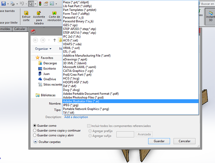
Within Solidworks export processes, it allows us to send our file to various formats for the different processes that we might need. For this process we export the files in a bidimentional format (AI) which was opened in Illustrator to be able to attach the pieces in the cutting bed.
Another process that offers this program is to simulate the ensables integrates the piece designed in a file of ensables with which position restrictions are linked between them.
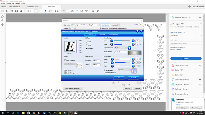
For make a cutting in the Zing. I generate a PDF file, select print, and put the configuration in the machine.
the only limitation is the size cut of the machine
MDF CUTTING CONFIGURATION:
Horizontal: 600
Vertical: 300
Speed: 30%
Power: 70%
Freq: 1300Hz
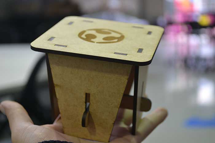
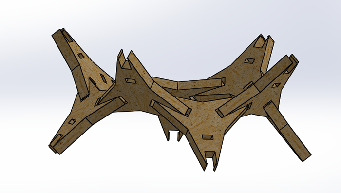
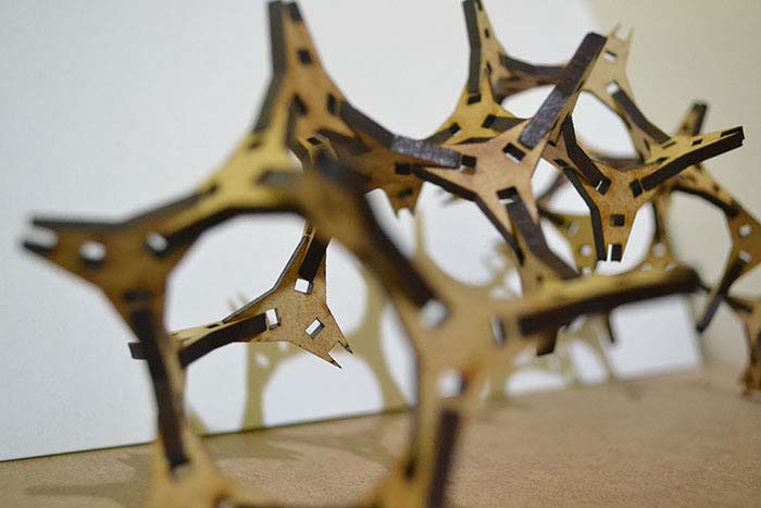
Once the pieces are generated, we carry out the unions creating the different forms for the study of the pavilion.
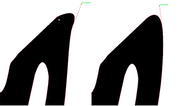
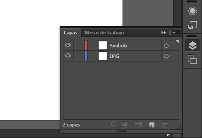
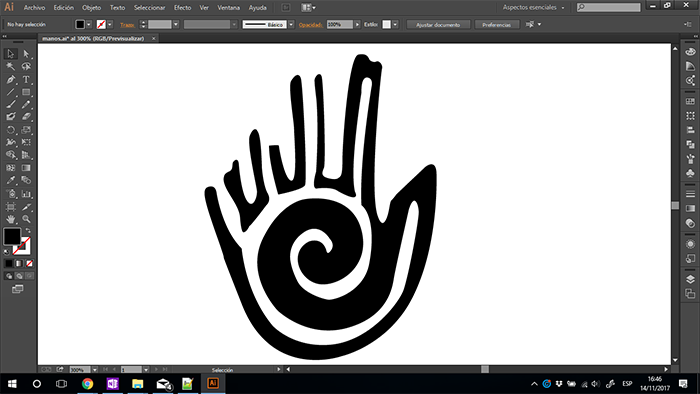
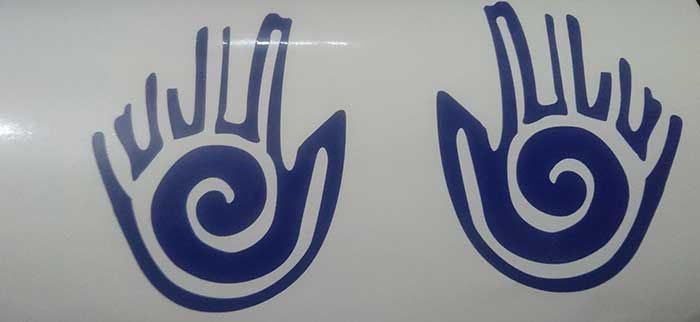
For the design Illustrator was used to redraw a pre-Columbian symbol of the Jama Coaque culture which represents the law of reciprocity, this symbol was one of the proposals for the logo for the redecorative of fab labs. In the design the pen tool was used, by means of this, an image of the symbol and the use of layers is proceeded to redraw the symbol by marking points with the right click of the mouse with a click a point is created and keeping this pressed you can create a curve between two points.
To vinyl cutting use the "ROHS MK2 365" small machine and "Sure Cuts A Lot 3 Pro" software. To this file, I make a pre-Columbian
design with represent the union of people.
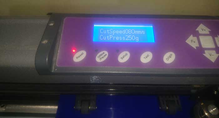
In the next image can see the configuration to make the cut.
In order to use this machine we will first know its main characteristics and how to calibrate.
SETTINGS:
This machine has a working area of 275 mm and its second measurement is undetermined since you can place all the royo by the back.
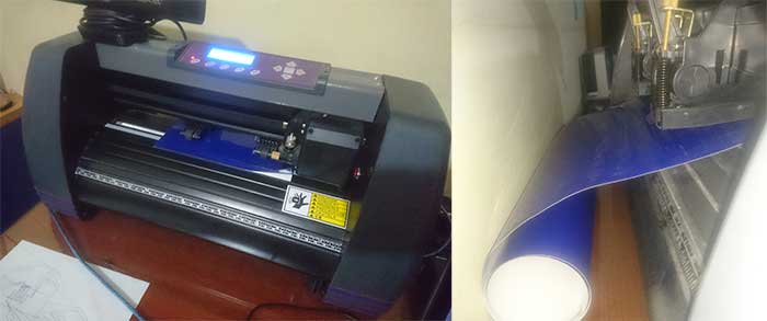
its speed range can vary from 10 to 1000 mm/s which is defined in conjunction with the cutting pressure which can vary from 10 to
600g has a screen and buttons with which we can configure the changes mentioned above.
Next you can see the used configurations
SOFTWARE
In the use of the software allows us the files created in Illustrator. we import the designed files and place it in the lower right
corner since it is point 0 of this machine.
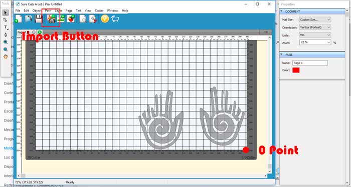
As a last step we send the file to machining to perform this step in the CUTTER tab select CUT WITH USCUTTER.
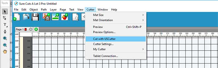
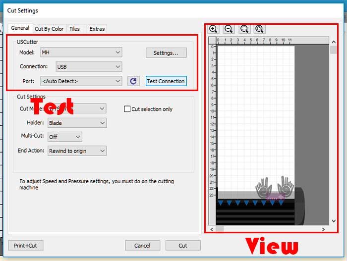
In the next screen we will have to make sure that our machine is correctly connected to our computer by clicking on the TEST CONNECTION
button and in the right window we have a preview of our design to be machined.
if this is ok we will click on CUT and this will send the file to cut on the machine.
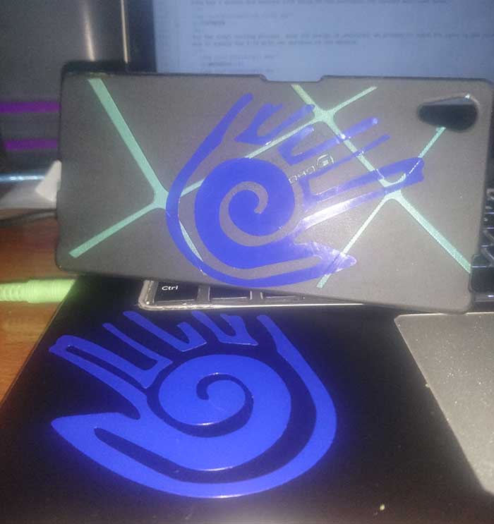
For this cut we chose vinyl adesivo blue.
Final
Laser cut:
In the laser cutting process it was very fun to be able to work to contribute in this great project on the "PABELLON LAT".
It was very important for me to be able to collaborate with the members of the LAT network and to work together with many of them. It is one of the most important projects of my Fab Academy because of the great impact.
Vinyl:
In the vinyl process I liked being able to experiment with the pre-Columbian figures for all the cultural impact that these generate in our locality.