Materials, tools and software
Electronic components (Materials)
Copper Plaque (Materials)
FabTotum (Tools)
Eagle (software)
Fab Modules (Software)
FlatCam (Software)
 |
 |
 |
 |
|---|
Electronic components (Materials)
Copper Plaque (Materials)
FabTotum (Tools)
Eagle (software)
Fab Modules (Software)
FlatCam (Software)
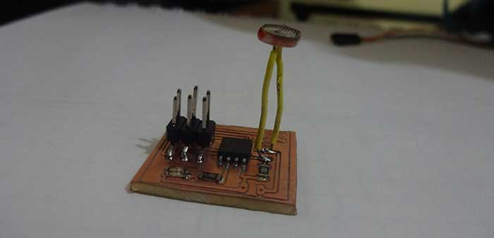
For this assignmetn a board was developed which is responsible for capturing an analog signal by means of the LDR sensor by which we can perceive variations of light. To accomplish this, an attiny 45 with a pin with analog input will be used to capture the voltage variation of the sensor.
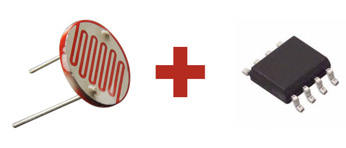
Attiny 45
LDR
Resistance 10k
Resistance 220 ohm
led
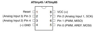
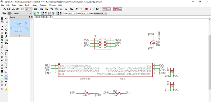
To carry out the design of the board, in the software we place all the aforementioned components in order to generate the connection to be able to comply with this, we are guided in the datasheet of the attiny 45 micotrolador. Also remember to keep the pins to burn bootloader.
It is understood as the ability of some devices which allow us to be programmed while they are already installed in a more
complex system, this means that it does not need to be programmed before being installed in their interaction system.
Within a wide variety of benefits the main one that we can find is to avoid carrying out the programming process before the
assembly as with other devices instead of doing it in this way we can program it in one step within the performance tests.
Also being the advantage the edition of the same programming in order to improve it.
Most of the devices that use this method use the JTAG (JOINT TEST ACTION GROUP) protocol in which it is used for the sub-module
test of integrated circuits. This is also very useful to identify and correct errors of embedded applications.

in the datasheet we can find the information on all the pins that the micorcontroller has and if they are analog or digital in this compose we have 3 analog and 6 digital.
to be able to control the LDR sensor with the microcontroller we will need an analog pin and to be able to verify this we will use a led connected to a digital pin which will turn
on and off based on the light capture of the LDR.
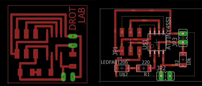
Subsequently perform the generation of tracks tracks and the development of the plate with a led which will help us to
demonstrate the proper functioning of the sensor.
In this process we use a machine different from the previous one the Fab totum with its head for CNC machining.
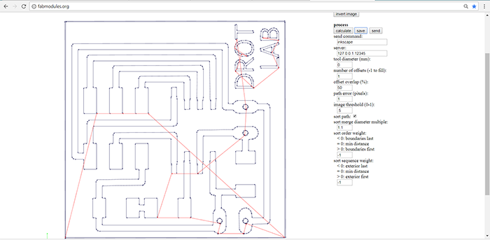
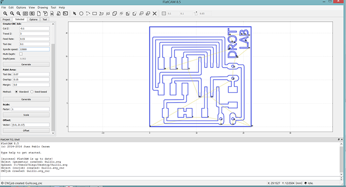
To generate the files we use a program called flatcam which receives the files in SVG formats so we save it in eagle
as a PNG format and in the FAB MODULES we transform it to SVG and in the software it transforms them into NC, format
that supports the machine before mentioned.
Once we obtain the .NC files we import into the machine software for machining, to accomplish this process we use a ten-degree tool.
We check that the tracks have been made properly and solder the components.
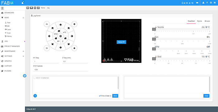
As a next step we proceed to add the file in the machine to machine. we use Fabtotum which uses Fab ui as a driver software, a very
simple program to which you only load the file and calibrate the machine to machine.

As next step we proceed to solder the components on the electronic board.
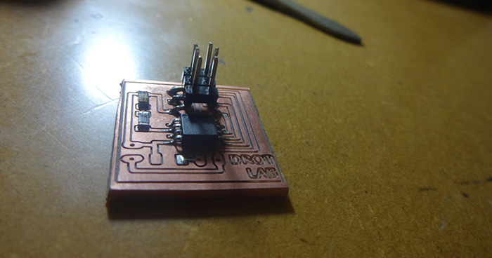
Final Board
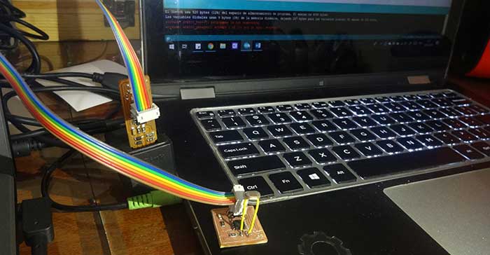
As a first step we burn the bootloaders with the enabled pins of the MISO microcontroller, MOSI VCC, GND, SCK and RESET. Once created
this process we generated the programming for the operation of our plate.
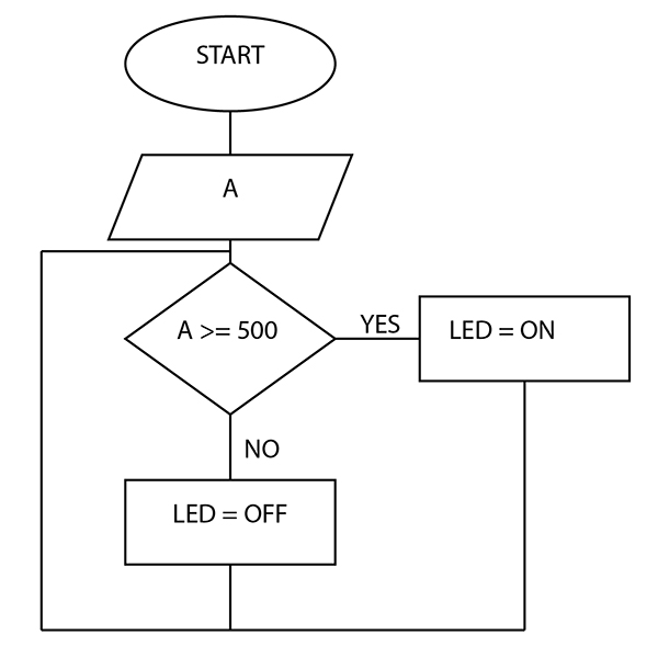
LOGIC:
START
-DECLATION OF VARIABLES
-CONFIGURE TICKETS AND DEPARTURES
-IF THE VALUE OF THE SENSOR IS GREATER THAN 500
-LED = ON
-YES NO LED = OFF
END
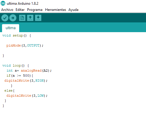
In the VOID SETUP, we declare PIN 3 as output with the pinMode command, which will be used to change the logic state to high by turning on the led. Within the VOID LOOP we declare a as an integer variable where the analog value of the input of pin A2 is stored. I use an IF condition in which I compare if the value of my variable is greater than or equal to 500, if this is the case I will enter the process changing the logical value of pin 3 lighting the led. If not, I use the ELSE condition where it ensures the low status of pin number 3.
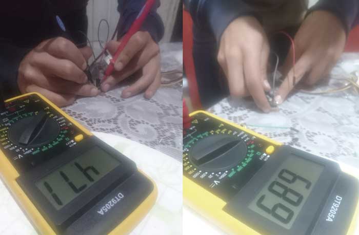
For the energy consumption of the plate we obtain a power supply voltage of 4.77v. Which is considered the operating range of the microprocessor to achieve its operation,
the board has a current consumption of 6.89mA. That this could vary depending on the use or the number of elements connected to the microprocessor.
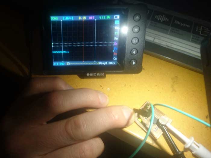
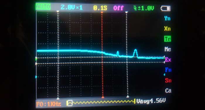
We connect the oscilloscope of the LDR sensor to measure its analog value, which is between 4.50 and 5 volts.
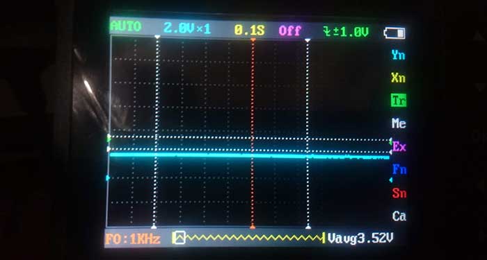
At the moment of approaching the light, a voltage drop occurs due to the reduction of the resistive value of the LDR obtaining a voltage of 3.52 volts, this depends on the intensity of the light.
In this week I learned the operation of an LDR element with which we can make a resistance variation due to the light intensity of the environment. With the help of the microcontroller I was able to make the valuation and data taking from the variation explained above. This could represent in an output in this case an LED which showed the analog variation going on from a required value based on the programming.