Design and build a wired &/or wireless network connecting at least two processors
Send a message between two projects
General
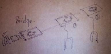
We need to build a network. We need to do a pcb called bridge and at least two other more called nodes or slaves
I will probably use Arduino SPI because it is very easy and I am familiar with it.
A concept I like is Bit-banging, which refers to the concept of having the signals which go out of or come into a device be generated/sampled by software rather than hardware. Obviously some hardware is required, but when using bit-banging, the only hardware for each output is a latch which can be explicitly set or cleared by software, and the only hardware for each input is an interface to allow software to test whether it is high or low (and typically execute a conditional branch for one state but not the other).
Another important concept is the Bus (computing), that “is a communication system that transfers data between components inside a computer, or between computers. This expression covers all related hardware components (wire, optical fiber, etc.) and software, including communication protocols.” Wikipedia.
MOSI Master Out Slave In
MISO Master In Slave Out
I²C (Inter-Integrated Circuit), pronounced I-squared-C, is a synchronous, multi-master, multi-slave, packet switched, single-ended, serial computer bus invented in 1982 by Philips Semiconductor (now NXP Semiconductors). It is widely used for attaching lower-speed peripheral ICs to processors and microcontrollers in short-distance, intra-board communication. Alternatively I²C is spelled I2C (pronounced I-two-C) or IIC (pronounced I-I-C).
I²C uses only two bidirectional open-drain lines, Serial Data Line (SDA) and Serial Clock Line (SCL). Wikipedia
What I need
Hardware
· Roland SRM-20
· Soldering gun
· Heat gun
· Electronic components
Software
· Eagle
· Arduino
· SPI
· I2C
References
Individual assignment:
I want to connect two humidity sensor as slaves to the master, and read the humidity in a monitor in the computer.
Design
and build a wired &/or wireless network connecting at least two processors
I think I will use I2C
Master
/ Bridge
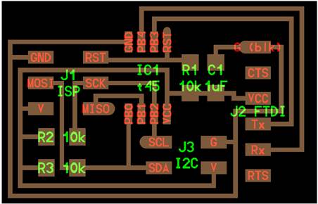
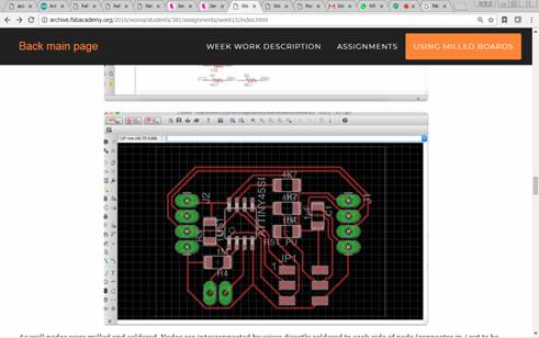
1. Make the file to mill the pcb of the Bridge from the traces and interior Neil put on the Fab academy page
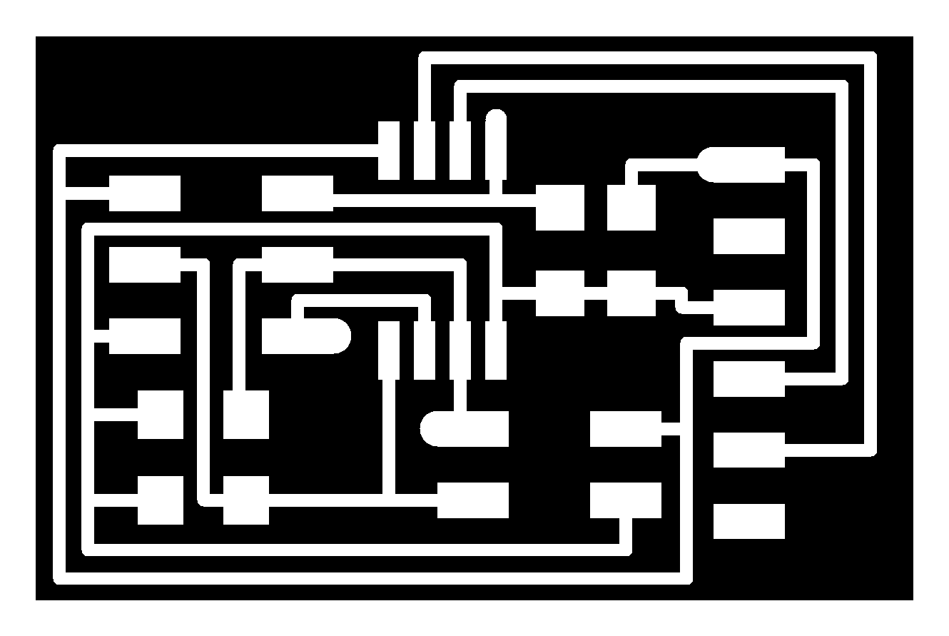
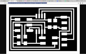
2. Save the png and open it into fabmodules to make the .rml file
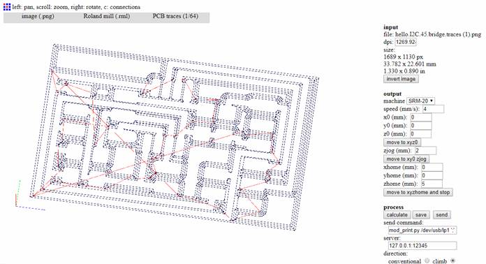
3. Put the file on a USB and go to the Roland
4. Do the same with the interior file
5. Just to remind, in the week 5 I put the step to mill with the Roland
6.
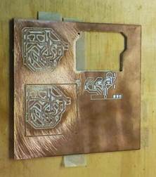
And
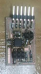
here is the board milled
I sanded it because the end mill is not that good and the board was a little
bit hairy
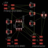
7. The components
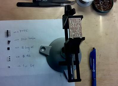
a. 2 2x2 header
b. 1 attiny 45
c. 3 10k resistors
d. 1 ftdi header
e. 1 uf capacitor
Node
/ Slave
1. I will adapt the nodes to what Roman KUT'YIN did in his assignment NETWORKING AND COMMUNICATIONS
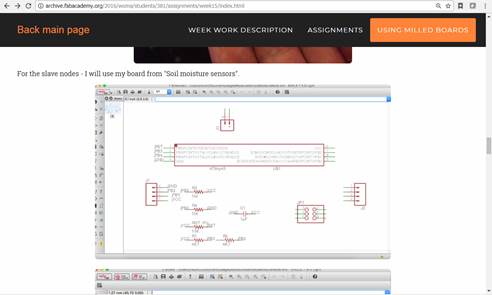
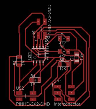
2. Here my adaptation
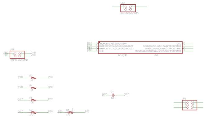
3. Then I realized that two headers weren´t connected, so I watched carefully the board image and with the logic of some of the headers that have to be always connected in the same pin with vcc, gnd etc, I completed the schematic.
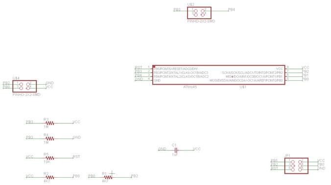
4. No ERC
5. Switch to Board
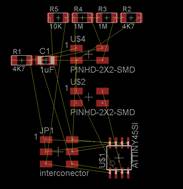
6. Arranging
7. I saw a this Eagle Autorouter Tutorial
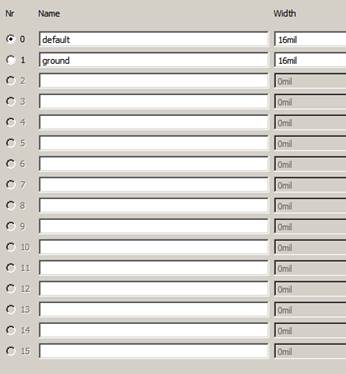
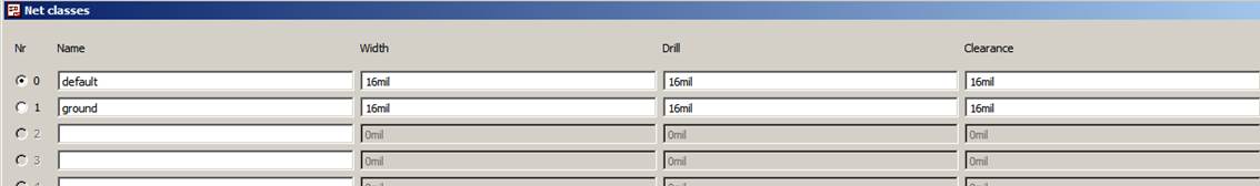
8. Edit / net classes / 16mil
9. Then in board view select Autorouter with the following settings
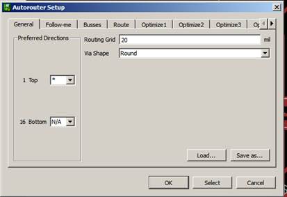
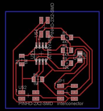
10. And here the result. I edited a little the lines to give more space between them
11. When I run de DCR of the eagle, I find out that there where many problems in the routing because some traces were too close from each other and wasn´t enough space for the mill to pass trough. So I went to the schematic again and defined the net classes better
12. Autorouting again
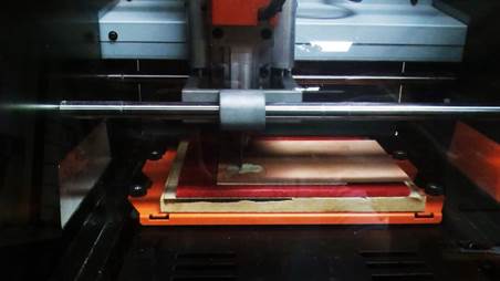
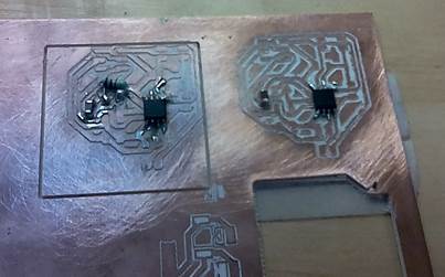
13. Print, fab module and mill the board
14. Don’t know why the Roland cuts the shape of the outline in the air, not in the pcb surface. I tried all the ways possible. The best I could is that the 1/32 end mill made two rounds of the outline, but didn´t the third round, so it didn´t cut the pcb. I think the problem is exporting the outline and making the file in fab modules.
15. Besides we ran out of components in the lab, and the big order is delayed so I started soldering the components for prototyping… but one resistance took like 15 minutes and it didn´t get well.
Arduino test
I don´t think I will finish soon, so I decided to test the assignment with Arduino before testing it with the pcb while I finish them
1. Take 2 Arduinos
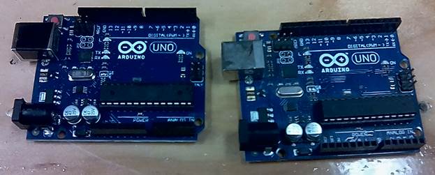
2. One Arduino will play master, and the other one is going to be slave. The master Arduino will send messages ON and OFF to slave node. Slave node will apply ON or OFF state on the LED and we will see that it change it state.
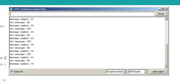
3. So below is the code for the slave node. This node has address 8. It uses kind of interruption in Arduino style code in Wire library. And on event "onReceive" - subroutine will be execute that will get message from the IIC communication and compare it to rules and change state of LED. As well message is sent to serial that we can see it for debug purpose (when we connect to USB slave node - we can read it)
#include <Wire.h>
String getString;
int led = 13;
void setup() {
Wire.begin(8);
Wire.onReceive(receiveEvent);
Serial.begin(9600);
pinMode(led, OUTPUT);
digitalWrite(13, HIGH);
}
void loop() {
delay(100);
}
void receiveEvent(int howMany) {
getString="";
while (1 < Wire.available()) {
char c = Wire.read();
getString +=c;
}
Serial.print("Got message: ");
Serial.println(getString);
if ( getString == "OFF"){
digitalWrite(led, LOW);
}
if ( getString == "ON"){
digitalWrite(led, HIGH);
}
int x = Wire.read();
Serial.print("Message number: ");
Serial.println(x);
}
4. And next code is the sketch for master node. It is simpler one as it opens communication to node with address 8. Then it send there one of two messages (ON or OFF) and byte that show the message number. It also interesting to check if we disconnect wire and cut the communication - if the message will be lost or communication will be hanged until the node arrives. (TBD).
#include <Wire.h>
void setup() {
Wire.begin(12);
}
byte x = 0;
void loop() {
delay(500);
Wire.beginTransmission(8);
Wire.write("ON");
Wire.write(x);
Wire.endTransmission();
x++;
delay(500);
Wire.beginTransmission(8);
Wire.write("OFF");
Wire.write(x);
Wire.endTransmission();
x++;
}
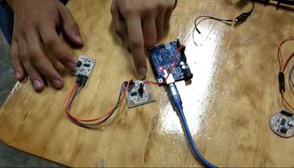
5. Connection is simple - pins 4 and 5 are interconnected between the Arduino (not required to cross them as each node connect always to SDA and SCL wire). Also GND and VCC5v are connected to avoid to power second Arduino board separately.
6. Master is working and the node Arduino is blinking. Video
7. Slave or node is working
Board task
I decided to use again the electronic Design board. I think I underestimated the use of this board. Once I learned more about boards I found out that that little board and exercise could be useful for other tasks. Two make the boards communicate between them, I needed to build another board the same.
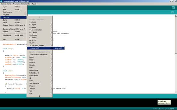
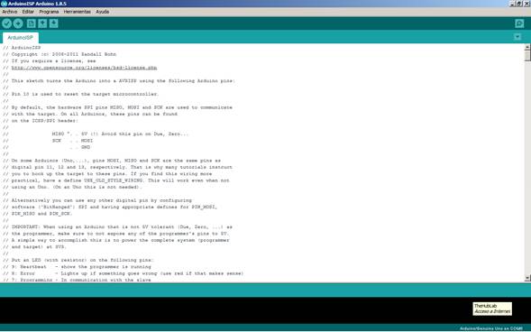
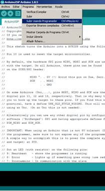
To start I program an Arduino Uno as programmer. To download codes into the boards, once the Arduino is connected I uploaded the code that is in File / Examples / ArdunoISP / ArduinoISP.
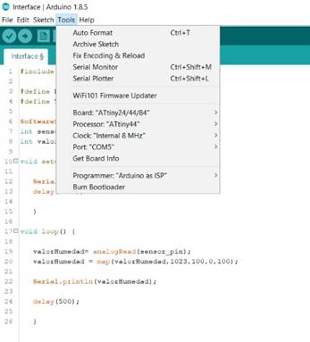
Connect the first board with the ribbon cable to the Arduino, which has pins for that cable, not the regular that we all use. Just had to connect the reset (RST) to the usual pin 10, because the other one don´t work well when programming another board. I configured the Arduino IDE to bootload with the specifications of the board. Attiny44, internal Clock 8mhz. Burn Bootloader !. After that you can upload any arduino code to the board, but using Upload using programmer. This code will made the other led of the board blink. So one Arduino commands the other blinking the led when you press the button.
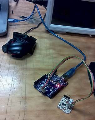
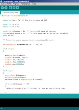
Yo do that I conected one board to the Arduino juts to give power to the board, using two junpers, one for VCC and the other for GND. Each board is interconected with the other by VCC and GND also, but RX and TX are switched, I mean that the rx from one board goes to the tx od the other one, and viceversa.
Group assignment:
Send a message between two projects
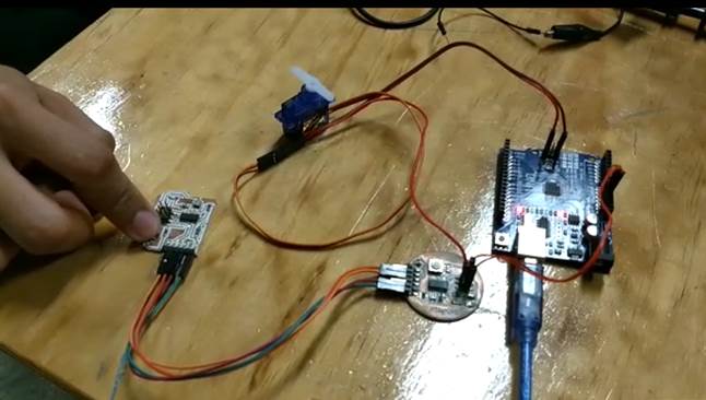
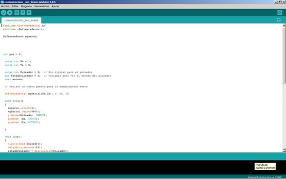
We took Ileana´s electronics Design Board and we make it communicate with mine, but in a different way. In one direction we made turn a servo and in the other direction (from the second board to the first one) just blink the led.
We just have to repeat the process above in Ileana´s board. But Upload a different code that controls the servo.
Download files / Descargar archivos