week 17/ Semana 17
actuate and automate your machine
Document the group project and your individual contribution
General
We will continue of course with our machine. Now to insert the electronic parts that will make it move. For now it will be Arduino. This will be part of my final project, so in the near future I will remake it with a PCB board.
What I need
hardware
· Screwdrivers
· Arduino board
· Cables
· Motor driver Nema A4988
Software
· Arduino program
group assignment
So far I was designing the general Machine and Ileana, my partner is in charge of the sensor and the little details of the machine like bearings (that we fabricated by ourselves). Now I will attach the arduino and cables to the machine, she will do the web page of the assignment and both will program the Arduino with the help of our friend Jesus
actuate and automate your machine
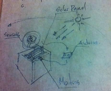
We are checking references. Last year in Barcelona a group did also a solar tracker . The difference is that they have one axis rotating at the bottom. Ours is more like the rotocasting machine another student did before (rotational casting machine by Saverio). So it is a combination of both.
Document the group project and your individual contribution
First try
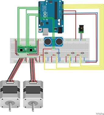
1. Collect the components. Arduino Pro-Mini and Nema driver.
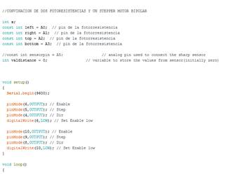
2. Download the Arduino code that the Solar tracker team did in Barcelona last year, as reference.
3. Try to connect everything like this, but mounted on the structure
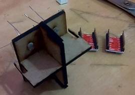
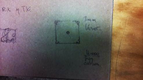
4. Put the 4 photo-resistances in the base. We put some tape in the back so the sensor keeps in place. Otherwise they are kind of loose.
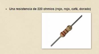
5. The resistance for the sensor
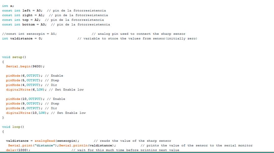
6. Checking the sensors. Put all the sensor in a bread board and test the arduino code
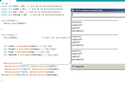
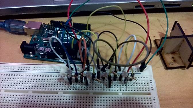
Close to 1023 under shadow, lower when the light comes
7. Video Solar tracker arduino test
Embeber
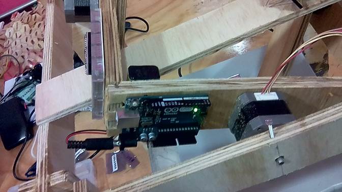
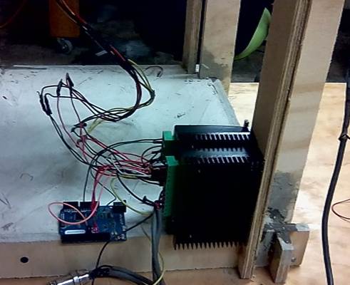
8. Fixed the components to the frame. Arduino and breadboard
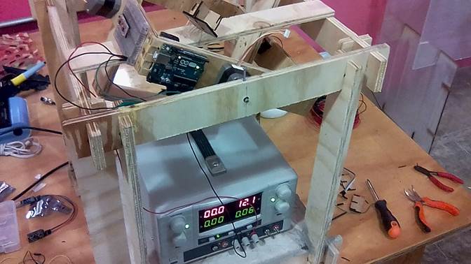
9. Connect the power source. 12v
10. Connected the sensors to the arduino and bread board mounted into the frame
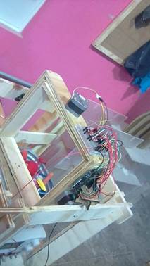
11. Unfortunately the machine didn´t work. The motors didn´t move the frames.
Second try
The reasons why it wasn’t working were:
· The motors were not strong enough to move the frames
· I burned the drivers for the Nema
· There were to many cables exposed
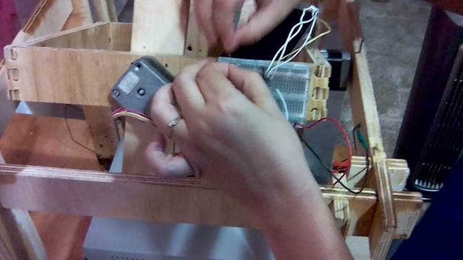
1. I put everything together again to see if the motors worked, but we changed a few things before. I have to order the cables.
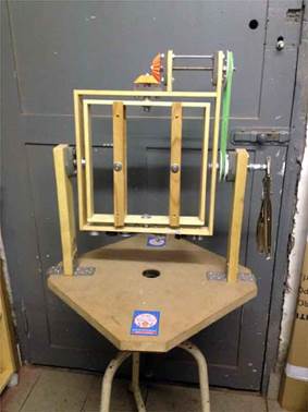
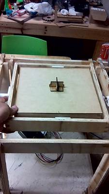
2. We put a table on the inner frame to hold the sensors in the middle. That is supposed to be the solar panel.
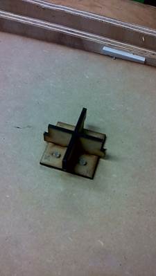
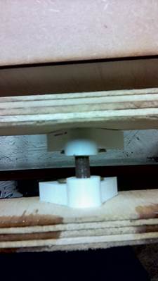
3. Printed again the bearings in 3d
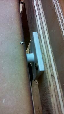

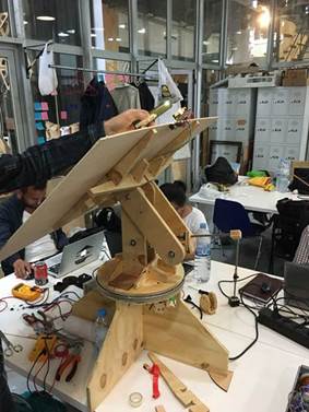
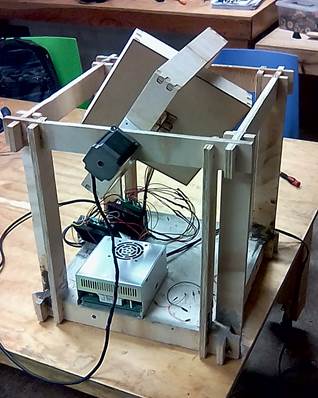
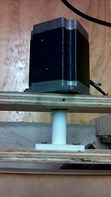
4. We put a bigger motor in outer frame which needed a bigger torque
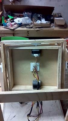
5. For the inner frame we put two nemas which together give the right torque. One must rotate opposite to the other
6. I fixed the drivers and arduino. And I still have to hide the cables. Probably with a table on top of it
7. Uploaded the Arduino code I developed for the machine
Download files / Descargar archivos