Week 13
add an output device to a microcontroller board you've designed, and program it to do something
measure the power consumption of an output device
______________________________________________________________________--
Introduction
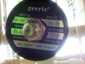
I choose an output I will use in my final Project. Open and close a Solenoid. I will test if the Solenoid works, if the extra circuit with mosfet on a breadboard works and if the code to open and shut the valve is right. As microcontroller I will use a FabDuino., because it is very useful for another assignments. I decided for the PCB to do a FabDuino or FabKit to be able to improve and make it more complex from here to the final project. I will open or close the solenoid valve. That’s why I selected the AtMega instead of Attiny. 1. The numbers of pins will allow me to connect more devices to the same board in the future. 2. The capacity of the microprocessor in memory and handling other components at the same time. 3. Easy to find libraries to program
Why this Output
I selected this output because is an important part of my final project. This will be the output that will keep the plants with enough water when they are dry. The sensor will send the signal to the board and by the minimum controlled by the potentiometer almost any plant could fit into this system easily because this minimum is regulated manually, but the opening of the solenoid is automatic. . For now it is just only opening and shutting the solenoid. For now this assignment was very useful because helped me to test the components and their requirements in terms of voltage, extra resistance, mosfet, etc.
add an output device to a microcontroller board you've designed, and program it to do something
electronics
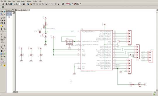
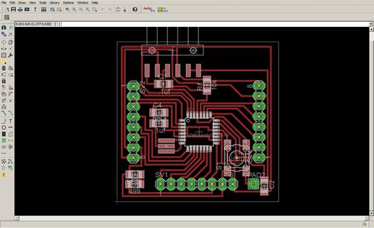
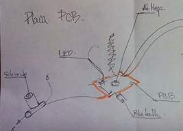
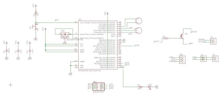
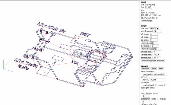
I redraw the fabduino in Eagle
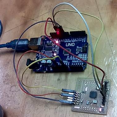
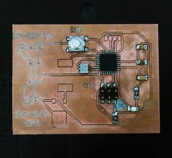
Once the PCB was cut, I proceeded to weld its components. In the Lab there was no AtMega, so I recycled one from a damaged Arduino. I learned the technique of unsoldering and welding with a heat gun. It should be placed at 500 ° C and left very close to the arduino so that the tin loosens and the plate is released, taking it with a clamp. Then the microprocessor is placed on the PCB that I cut and as it brings tin still attached to its legs, when placing the gun again very close, the tin adheres to the traces. (Previously it is necessary to place solder paste on the plate to help the adherence of the tin to the traces)
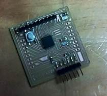
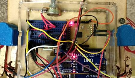
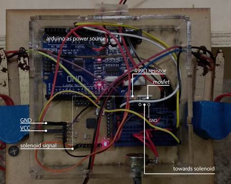
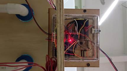
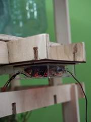
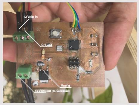
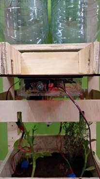
I put pins all around the board to make it easy to connect and disconnect with jumpers. I connected the sensors to the analog pins. Extra, I had to make a breadboard with a mosfet to be able to control the solenoid valve. At the moment of powering the circuit I saw myself in certain difficulties. The solenoid I fed it with a power source that would give 12v. And for the board, I used an Arduino, but only as a current transformer, I connected a 9 volt battery to the Arduino that only fed fabduino with the 5v voltage that it required. I put everything in an acrylic box to protect the circuits and to be visible since the plate turned on and off its LED also depending on the humidity conditions of the soil. This box is placed under a piece to protect it even more, since it would be exposed to the elements. It is already mounted on my final project
Programming
I decided to use Arduino's language because it seemed the easiest for me and I'm already familiar with it. In addition, I can intuitively make the code more complex by adding more elements in the future for the final project.
Connect the Arduino to the computer
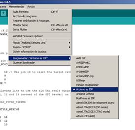
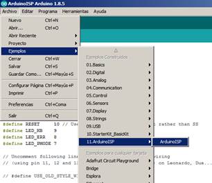
Open the Arduino IDE interface in: Files / Examples / 11.ArduinoISP / ArduinoISP
Select the Programmer: Arduino as ISP, otherwise it will fail uploading the code
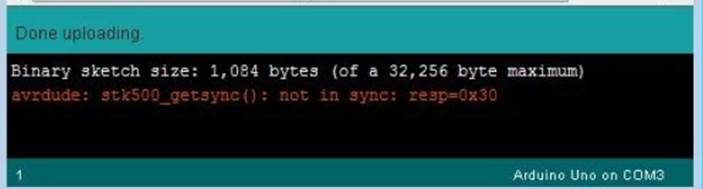
Upload that code to the Arduino (check that you are in the correct port)

It gave the same error again and again. One more time Jesus helped me. He told me that since the Arduino I was using is Chinese, I needed to download a driver for it.
CH340 driver for Chinese or generic arduino. When downloading and installing it the code was uploaded without any problem to the connected Arduino.
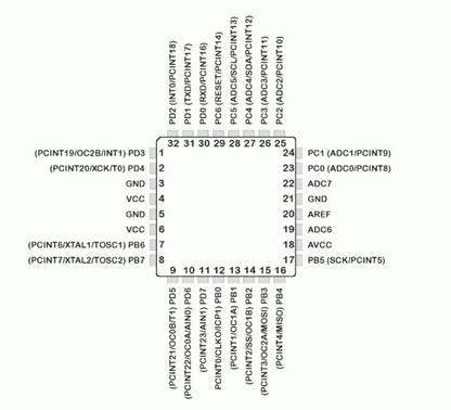
Connect the arduino to the board to program it. You have to check which pins of the Arduino programmer you have to connect, which are:
RESET 10
PIN_MOSI 11
PIN_MISO 12
PIN_SCK 13
VCC
GND
These will have to connect to the same pins on the PCB that you want to program. For which it is necessary to review the datasheet and see which pins correspond to connect them to each other. Review Arduino as ISP and Arduino Bootloaders
DTR = Reset
AtMega voltage, between 3 and 5.5
The next step once everything is connected between the Arduino and the Fabduino is to make a bootloader of the same code that was uploaded to the Arduino. When I did this, I got an error. I checked the PCB and found that there were some poorly welded parts and I fixed them. But another error persisted and I have not been able to solve it.
avrdude: Expected signature for ATmega328P is 1E 95 0F
Double check chip, or use -F to override this check.
Error quemando bootloader
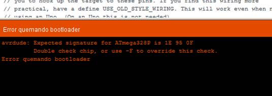
The solution was that every time that message appeared, the computer had stopped detecting the Chinese Arduino, so I had to install the driver again every time.
Having overcome this problem, I wrote my Arduino code. I just want to open and close the valve. In the future I will add sensors
/ This is the code
int solenoidPin = 4; //This is the output pin on the Arduino we are using
void setup() {
// put your setup code here, to run once:
pinMode(solenoidPin, OUTPUT); //Sets the pin as an output
}
void loop() {
digitalWrite(solenoidPin, HIGH); //Switch Solenoid ON
delay(1000); //Wait 1 Second
digitalWrite(solenoidPin, LOW); //Switch Solenoid OFF
delay(1000); //Wait 1 Second
}
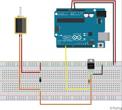
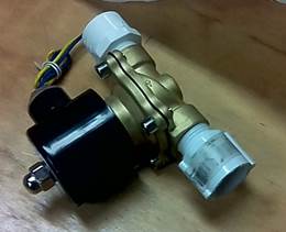
Connect the Arduino to the Solenoid. I need a mosfet and a resistance. A mosfet is a type of transistor that commutes the energy that goes to the Solenoid.
“To activate the solenoid, the microcontroller GPIO signal goes high causing the MOSFET to turn on. When on, the MOSFET allows current to flow from the power supply through the solenoid and to ground. The voltage rating for the solenoid dictates the voltage of the power supply (it is OK if the power supply voltage is different from the microcontroller voltage). The MOSFET should be selected to handle sufficient current to activate the solenoid as specified in the solenoid’s datasheet.
Because the solenoid is an inductive device, the diode is added to protect the MOSFET. When the solenoid turns off, the current through the solenoid rapidly drops from the nominal value to zero. Since the voltage drop across the solenoid is proportional to the change in current (see equation below), the current drop creates a voltage spike which can damage the MOSFET. The diode prevents the voltage spike from reaching damaging levels by directing the current back to the power supply.” From Controlling a Solenoid
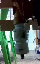
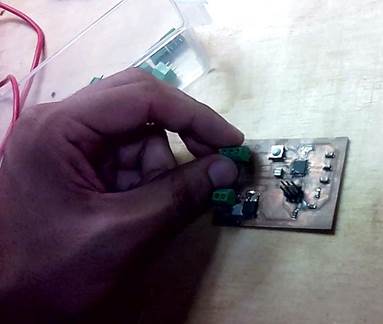
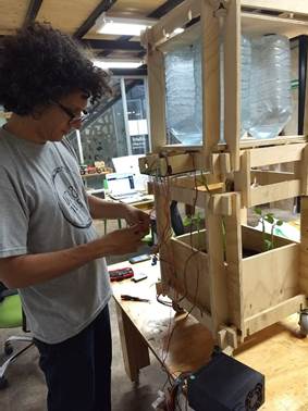
I put the structure upside down to work easier, because it goes below the wood piece to protect the circuit from the rain. I built a acrylic case to put all the cables inside of it, including my rafDuino (which changed for the Final project)
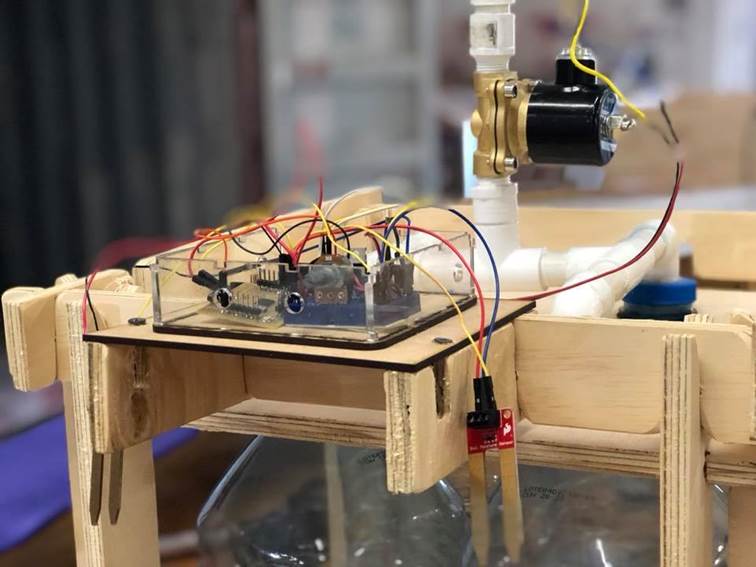
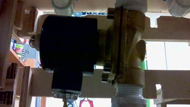
In my case I have to connect the pins, not to the arduino, but to the Fabduino. I have to check which pin from the Arduino is represented in the Fabduino and where. And the solenoid is not fed by the Arduino, because in my case I need 12v. I put a power supply for that. The valve is connected to 12” water pipes. The only pressure it will hold is the gravity of the water which is nothing for what the valve can handle.
I did work!
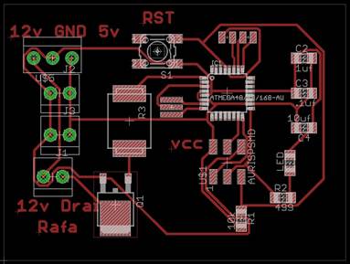
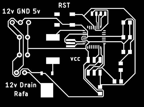
PCB Final
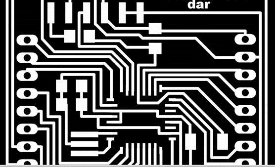
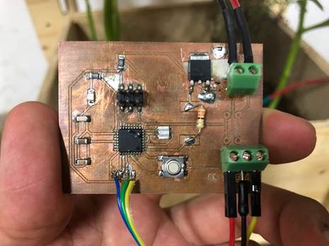
I replaced the FABduino Board, which worked as Test to know in an easy way that everything works. Now I did another board designed by me from scratch. There I connected the 12v Power source, the mosfet, and the 499ohms resistor which I built extra previously, but now it is integrated in the board. I designed it in Eagle, first in the Schematic dropping in all the components and then making traces of the Board. After that I made the PNG to make the gcode in the FabModeles to cut it in the Modela SRM-20. I soldered the components and install it all together into my final project replacing the previous FabDuino board I installed.
measure the power consumption of an output device
We used my board that I made in Electronic Design.
We connected a servo motor (Tower Pro. Micro serv 9g. sg90)
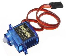
We programmed it with Arduino IDE to move 180° into one direction wait 15ms and move to the other direction
#include <SoftwareServo.h>
SoftwareServo myservo; // create servo object to control a servo
// a maximum of eight servo objects can be created
int pos = 0; // variable to store the servo position
void setup()
{
myservo.attach(1); // attaches the servo on pin 1 to the servo object
}
void loop()
{
for(pos = 0; pos < 180; pos += 1) // goes from 0 degrees to 180 degrees
{ // in steps of 1 degree
myservo.write(pos); // tell servo to go to position in variable 'pos'
delay(1); // waits 15ms for the servo to reach the position
SoftwareServo::refresh();
}
delay(500);
for(pos = 180; pos>=1; pos-=1) // goes from 180 degrees to 0 degrees
{
myservo.write(pos); // tell servo to go to position in variable 'pos'
delay(1); // waits 15ms for the servo to reach the position
SoftwareServo::refresh();
}
}
We powered the motor and the board from the arduino board that was connected to the computer. Then connected the motor to the trace that corresponds to the pin1 in the microprocessor. Connected the multimeter to the board.
|
state |
I (mA)) |
w |
w=V*I |
|
|
servo turned off |
3.4 |
0.01 |
||
|
5ms delay |
120 |
0.25 |
||
|
1ms delay |
170 |
0.85 |
Even when the servo is off, the microprocessor has a little power consumption. When we make the delay of the servo smaller the consumtion increase, because the motor works more in comparaison with a bigger delay.
Conclusions
· The solenoid valve is a powerful actuator because allows my project to receive water by just opening the valve, but the water comes by gravity, so the consumptions of energy in lower than using a water pump
· Hydraulic Solenoid opens and closes a small pilot valve, which in turn activates the main valve by applying fluid pressure to a piston or diaphragm that is mechanically coupled to the main valve. Solenoids are also in everyday household items such as washing machines to control the flow and amount of water into the drum. (Wikipedia)
· The term or of Solenoid is wider than just for a valve. “A solenoid is a type of electromagnet whose purpose is to generate a controlled magnetic field. If the purpose of the solenoid is instead to impede changes in the electric current, a solenoid can be more specifically classified as an inductor rather than an electromagnet” (Wikipedia)
Download files