Index
Measure something: add a sensor to a microcontroller board that you have designed and read it
Test the sensor with an Arduino
Measure the analog levels and digital signals in an input device
__________________________________________________________________________________________________________-
Introduction
This week we had to choose one input and make a board to make it work. Instead of using an Attiny 44, I made a Fabduino with a little modification (because I know I'm going to use it from now on) and humidity sensors
I choose an input I will use in my final Project. Read a humidity sensor. As microcontroller I will use a modified FabDuino., because it is very useful for another assignments (Output for example). I decided for the PCB to do a FabDuino or FabKit to be able to improve and make it more complex from here to the final project. I will open or close the solenoid valve. That’s why I selected the AtMega instead of Attiny. 1. The numbers of pins will allow me to connect more devices to the same board in the future. 2. The capacity of the microprocessor in memory and handling other components at the same time. 3. Easy to find libraries to program
Individual assignment:
I will make a Humidity soil sensor device. I will use this for my final project. I have boxes where people can grow things in the area with lack of main resources. Foo is one of them. If a device tells you when the soil is dry and need water, it will be easier to keep the plants alive and to just use the water when the plants need it, so the resource of water will be optimized.
Softwares
· Eagle
· Arduino
Hardware
· Roland MonoFab SRM-20
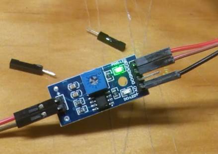
· YL-69 Sensor
· Breadboard
· Jumpers cables
· Battery 9volts
· Leds
· Resistances
Measure something: add a sensor to a microcontroller board that you have designed and read it
It took a while to understand how to do it by myself. I want to make a humidity sensor which will be part of my final project. A couple of weeks ago I did with my girlfriend a humidity sensor just with electronics (no microprocessor). I want to rebuild the sensor and of course make the boards that will transmit the data to the computer.
This is a video of the sensor we made
To have a better idea of what I have to do. I saw these documentations
MOISTURE SENSOR. A device as an activity for kids.
Moisture tester project. The whole activity explained from start to end. There I could see the components and how they work to sense the humidity. It is simple, it´s just a circuit that closes itself in the presence of moisture.
Matt Blackshaw / Week 8: Input Devices / Touchpad. With this FabAcademy documentation that Neil recommends, I understood that how I can make a generic transmit receiver device that will be connected to the sensor ad programmed to read the data and transmit it to the computer.
Week 11: / Input Devices / Objectives by Janaki. Explained me that I can build my own sensor. I am not sure if at the end it worked well for her, because at the end of the documentations she shows the sensor connected to the bread board and Arduino.
My first plan was (but it changed in the process):
1. Build a transmit receiver board
2. Design and build a humidity sensor
3. Program
4. Read humidity
5. If it doesn´t work at least I will use the sensor with a bread board and Arduino. Hope I won´t need to do that
Neil´s transmit receiver has a Attiny45, we have here 44. I will redesign the board with that.
But I asked and my tutor was not sure if that was going to work because of the difference of pins and memory of each one.
Anyway I think I have a better idea. I will edit my Electronic design assignment board. I mean start with that design in eagle. Erase the led and add a another header
Ok, enough. First I will do the sensor with the Breadboard and check with Arduino if it can read the fluctuations
Diy SENSOR
First try
I used this tutorial from Youtube. Didn´t work. Probably I did something wrong.

Now I know. I was connecting the board wrong. The left side of the GND and VCC is split from the right side. So anything that I connect on one side will not feed anything that I connect on the other side… beginner error
Next…
Second try
Will try this tutorial, a friend (Rodrigo) recommended me. Práctica 7: Sensor de humedad
But I don´t find the components in the lab like the 15k and 220 ohms resistor
Third try. The right one
I try replicating the existing sensor I showed in the beginning and it didn´t work neither.
But I showed it to a friend and told me a committed a mistake of beginners. The breadboard on the line of current cuts the continuity in the middle. So I had the battery connected to one side and the rest in the other. I put everything on the same side and it worked. The led turned on in the contact of soil with water.
Test the sensor with an Arduino
I will follow what Janaki did.
1.
Download
the arduino library
“Now, here is the commented Arduino code for a capacitive sensor -- please note
that you need the Capacitive Library from Arduino to run this, and you can find
that here.” Janaki
2. Add library to your software
3. I tested this in the Interface Programming week. Even I know I should not use Arduino as assignment I just do it to understand better the logic and practice the processes.
RafDuino (test)
I changed the strategy. As I said in the introduction I will make it work with the fabduino I modified to test all components and then replace it with my own board.
Electronics
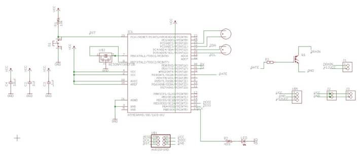
I redesigned the fabduino in Eagle
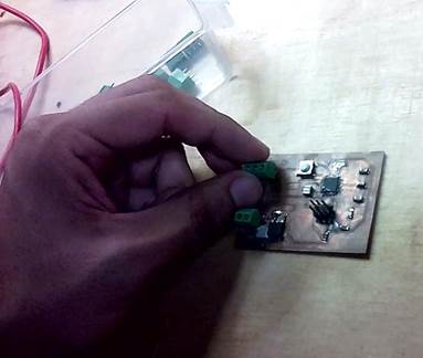
Once the PCB was cut, I proceeded to weld its components. In the Lab there was no AtMega, so I recycled one from a damaged Arduino. I learned the technique of unsoldering and welding with a heat gun. It should be placed at 500 ° C and left very close to the arduino so that the tin loosens and the plate is released, taking it with a clamp. Then the microprocessor is placed on the PCB that I cut and as it brings tin still attached to its legs, when placing the gun again very close, the tin adheres to the traces. (Previously it is necessary to place solder paste on the plate to help the adherence of the tin to the traces)
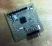
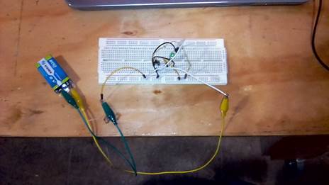
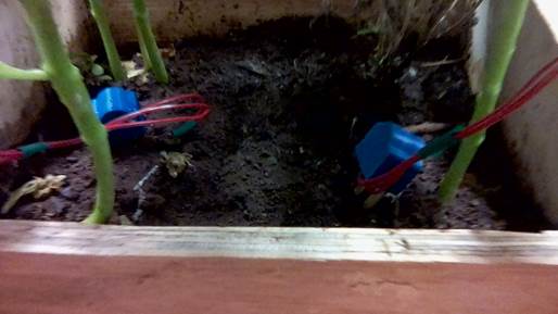
I put pins all around the board to make it easy to connect and disconnect with jumpers. I connected the sensors to the analog pins, I used an Arduino, but only as a current transformer, I connected a 9 volt battery to the Arduino that only fed fabduino with the 5v voltage that it required. I put everything in an acrylic box to protect the circuits and to be visible. This box is placed under a piece to protect it even more, since it would be exposed to the elements. It is already mounted on my final project. Everything worked fine.

Final PCB
Everything worked with the FabDuino, so it is time to do my own board!
I designed in Eagle a new board for my final project, but also work for this assignment. I tested the one of the components of the device: The Input of the Soil Humidity sensors. Two sensors will be connected to the board, and the board is feed my power source of 5V. The connection is similar that the previous with the FabDuino, but easier because I don´t need the Arduino as Power source.
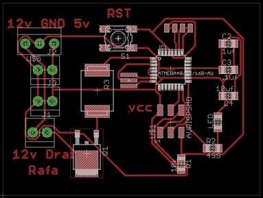
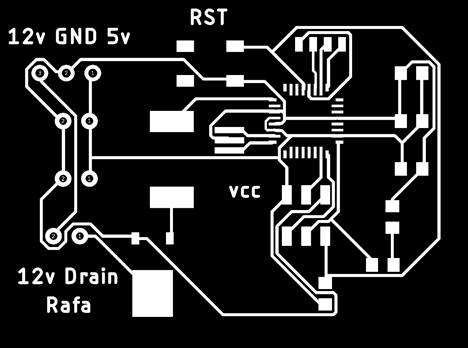

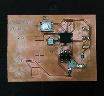


I cut it in the MonoFab Modela
I replaced the previous board ant test it with everything connected in my final project
Programming
I decided to use Arduino's language because it seemed the easiest for me and I'm already familiar with it. In addition, I can intuitively make the code more complex by adding more elements in the future for the final project.
Connect the Arduino to the computer
Open the Arduino IDE interface in: Files / Examples / 11.ArduinoISP / ArduinoISP
Select the Programmer: Arduino as ISP, otherwise it will fail uploading the code
Upload that code to the Arduino (check that you are in the correct port)


It gave the same error again and again. One more time Jesus helped me. He told me that since the Arduino I was using is Chinese, I needed to download a driver for it.
CH340 driver for Chinese or generic arduino. When downloading and installing it the code was uploaded without any problem to the connected Arduino.

Connect the arduino to the board to program it. You have to check which pins of the Arduino programmer you have to connect, which are:
RESET 10
PIN_MOSI 11
PIN_MISO 12
PIN_SCK 13
VCC
GND
These will have to connect to the same pins on the PCB that you want to program. For which it is necessary to review the datasheet and see which pins correspond to connect them to each other. Review Arduino as ISP and Arduino Bootloaders
DTR = Reset
AtMega voltage, between 3 and 5.5

The next step once everything is connected between the Arduino and the Fabduino is to make a bootloader of the same code that was uploaded to the Arduino. When I did this, I got an error. I checked the PCB and found that there were some poorly welded parts and I fixed them. But another error persisted and I have not been able to solve it.
avrdude: Expected signature for ATmega328P is 1E 95 0F
Double check chip, or use -F to override this check.
Error quemando bootloader

The solution was that every time that message appeared, the computer had stopped detecting the Chinese Arduino, so I had to install the driver again every time.
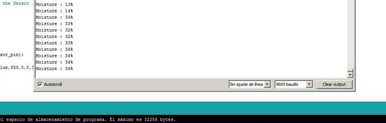
Having overcome this problem, I wrote my Arduino code. I just want to read the sensors. In the future I will add more sensors and actuators
/ This is the code
int sensor_pin = A0;
int output_value ;
void setup() {
Serial.begin(9600);
Serial.println("Reading From the Sensor ...");
delay(2000);
}
void loop() {
output_value= analogRead(sensor_pin);
output_value = map(output_value,1023,150,0,100);
Serial.print("Moisture : ");
Serial.print(output_value);
Serial.println("%");
delay(3000);
}
I tested the readings of the sensors trough the Arduino with the Serial Monitor of the Arduino program, and they were working fine.
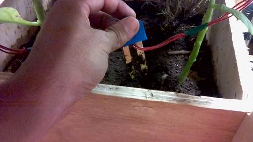
Everything is now connected to my final project. Since I cannot see the serial monitor from my board, I program the led on the board to torn on when the humidity in under 50%. I just put water in the soil to compare the sensor inside the soil and outside where s dry.
Group assignment:
Measure the analog levels and digital signals in an input device
We used the board made in Electronic design, with the push button to measure the digital signal and analog level
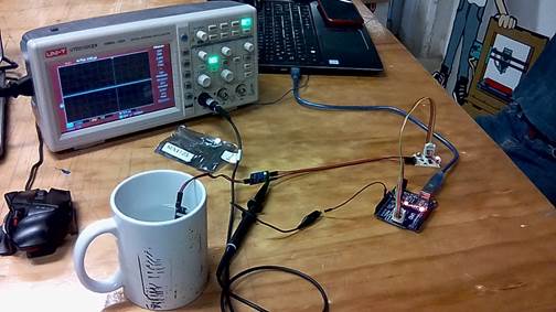
Analog Level
To measure this analog level we put the humidity sensor connected to the Electronic design Board.
We uploaded the Arduino IDE into the board connecting it into the analog pins of the microprocessor
When everything was connected, the levels went up and down with different heights depending how much we put the sensor in the water.
Digital Signal
To see this fluctuation we used the same board, but we changed where the pin was connected into the board, and also changed the pin where the signal was connected in the sensor. The sensor has both outputs (analog and digital). The difference with the analog is that the signal jumps from one height to another abruptly. The voltage goes from 0 to 5.5
Conclusions
· The moisture sensor measures the voltage that pass when the circuit is closed in the presence of water.
· The read if the moisture with the arduino is between 0 and 1023, but in reality. My reads never reached the limits, were always between 30 and 900 more and less.
· I have to find out a way to set the sensibility of the sensor from outside, because I will not be practical if I have to connect my computer to download another code to set the minimum humidity percentage to turn the led on or off in the valve…
Download files / Descargar archivos