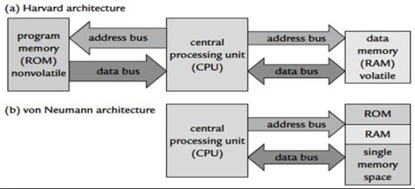
Harvard architecture has separate data and instruction busses, allowing transfers to be performed simultaneously on both busses. A von Neumann architecture has only one bus which is used for both data transfers and instruction fetches, and therefore data transfers and instruction fetches must be scheduled - they can not be performed at the same time.
It is possible to have two separate memory systems for a Harvard architecture. As long as data and instructions can be fed in at the same time, then it doesn't matter whether it comes from a cache or memory. But there are problems with this. Compilers generally embed data (literal pools) within the code, and it is often also necessary to be able to write to the instruction memory space, for example in the case of self modifying code, or, if an ARM debugger is used, to set software breakpoints in memory. If there are two completely separate, isolated memory systems, this is not possible. There must be some kind of bridge between the memory systems to allow this.
Using a simple, unified memory system together with a Harvard architecture is highly inefficient. Unless it is possible to feed data into both busses at the same time, it might be better to use a von Neumann architecture processor.
Use of caches
At higher clock speeds, caches are useful as the memory speed is proportionally slower. Harvard architectures tend to be targeted at higher performance systems, and so caches are nearly always used in such systems.
Von Neumann architectures usually have a single unified cache, which stores both instructions and data. The proportion of each in the cache is variable, which may be a good thing. It would in principle be possible to have separate instruction and data caches, storing data and instructions separately. This probably would not be very useful as it would only be possible to ever access one cache at a time.
Caches for Harvard architectures are very useful. Such a system would have separate caches for each bus. Trying to use a shared cache on a Harvard architecture would be very inefficient since then only one bus can be fed at a time. Having two caches means it is possible to feed both buses simultaneously....exactly what is necessary for a Harvard architecture.
This also allows to have a very simple unified memory system, using the same address space for both instructions and data. This gets around the problem of literal pools and self modifying code. What it does mean, however, is that when starting with empty caches, it is necessary to fetch instructions and data from the single memory system, at the same time. Obviously, two memory accesses are needed therefore before the core has all the data needed. This performance will be no better than a von Neumann architecture. However, as the caches fill up, it is much more likely that the instruction or data value has already been cached, and so only one of the two has to be fetched from memory. The other can be supplied directly from the cache with no additional delay. The best performance is achieved when both instructions and data are supplied by the caches, with no need to access external memory at all.
This is the most sensible compromise and the architecture used by ARMs Harvard processor cores. Two separate memory systems can perform better, but would be difficult to implement.
I recommend this post created by Sparkfun, (clic here!!) for people who have no experience reviewing a datasheet, where it is recommended to focus on the most important points of the item being reviewed.
Next, I present some characteristics of the microcontrollers that are used in the activities of the program to be considered when they are to be programmed that I have learned from the datasheets.
More information here
More information here
More information here
AVR FUSES
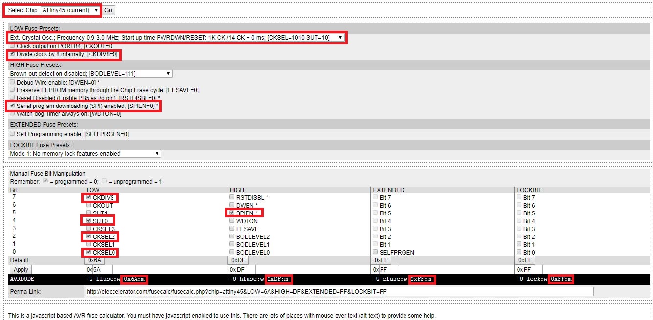
AVR microcontrollers have their configuration mechanism called fuses, which serve to configure important parameters of the microcontroller, such as its memory, working frequency, programming interface, bootloader, among others.
The AVR micros have configuration registers called Fuse Bytes, which in turn implement the bits, called Fuse Bits, to configure their characteristics. To know these fuses it is necessary to resort to the data sheet of the microcontroller with which you are working, some AVR microphones can have up to three Fuse bytes and others only one, depending on the characteristics of the micro. In the data sheet you can search for "Memory Programming", "LockBits", "Fuse low byte" or something similar to find information regarding fuses.
These registers or fuses are commonly called "Lfuse", "Hfuse" and "Efuse", or Low Fuse, High Fuse and Extended Fuse respectively. To calculate the value of the configuration registers it is necessary to enable and disable the bits of interest of each register and obtain their corresponding value in hexadecimal, to subsequently program these values in the microcontroller.
More information in the following link.
To see some fuses configuration you can visit this link This page rcommend the parameters required tu burn the fuses according the microcontroles we want to program.
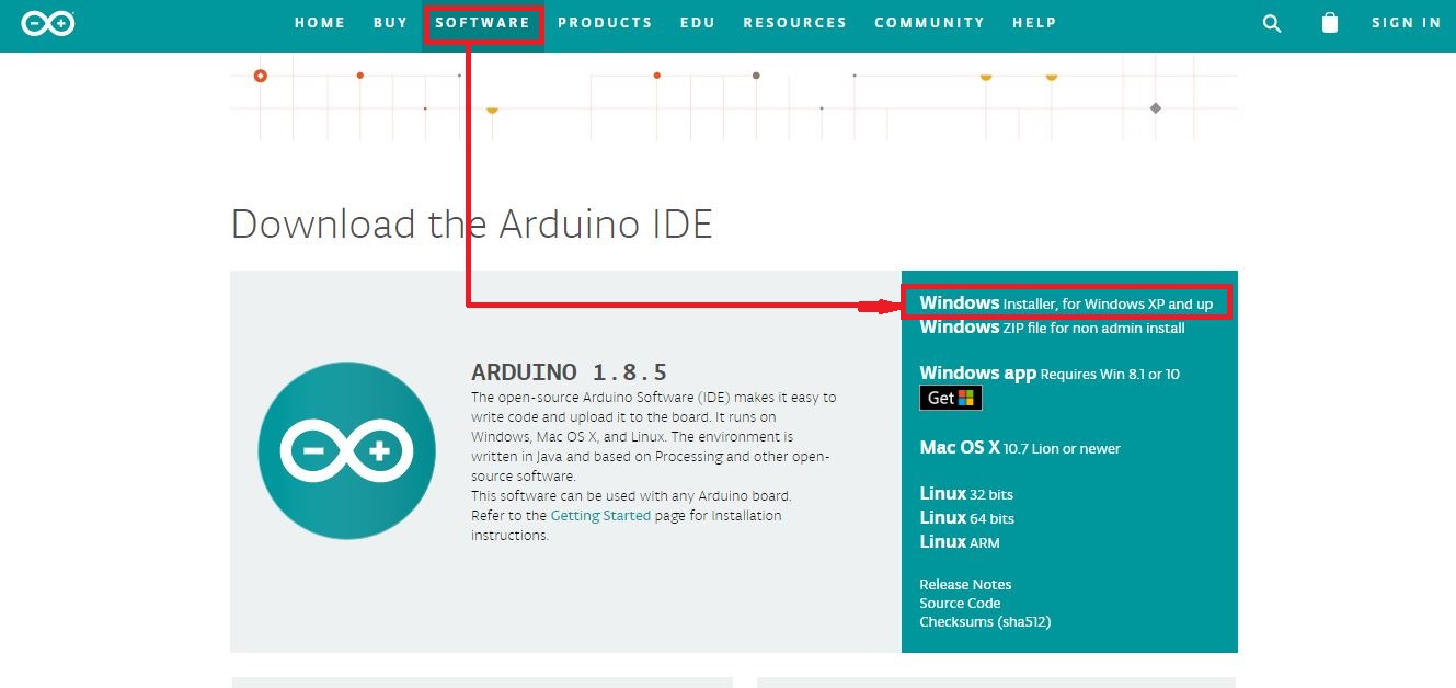
We will start the programming of the board by installing the Arduino IDE, for this we will download the programming software, enter the arduno.cc page and download the Arduino IDE installer.
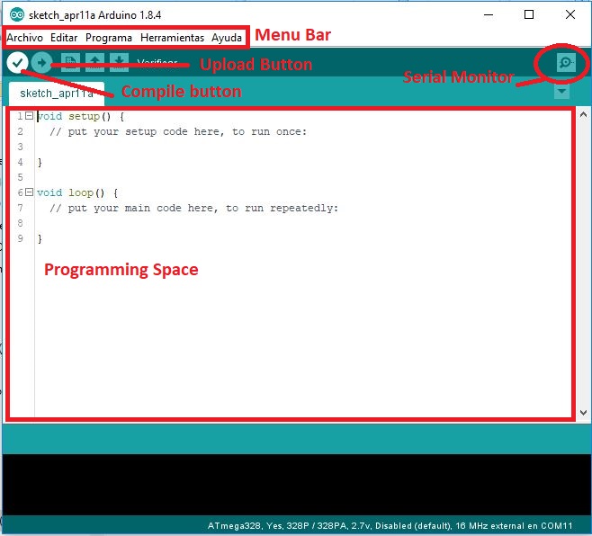
At the moment of executing the design software, the following window will be displayed:
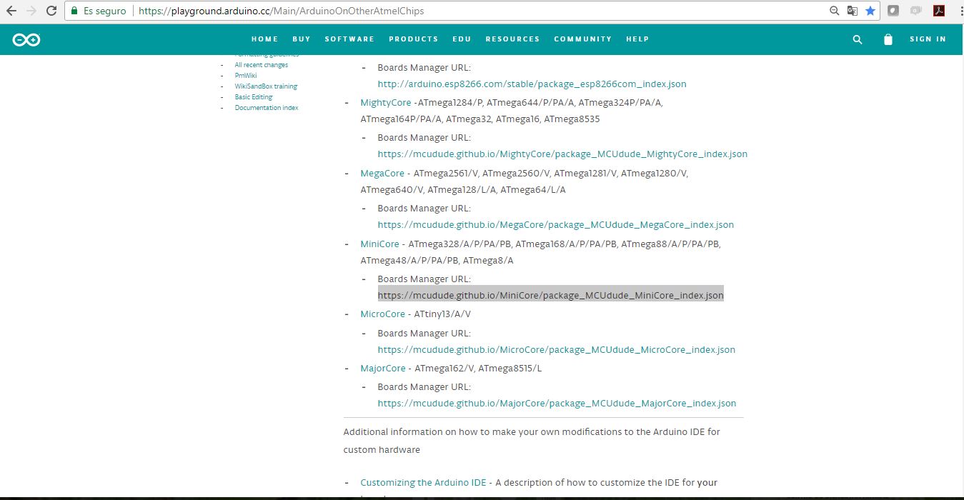
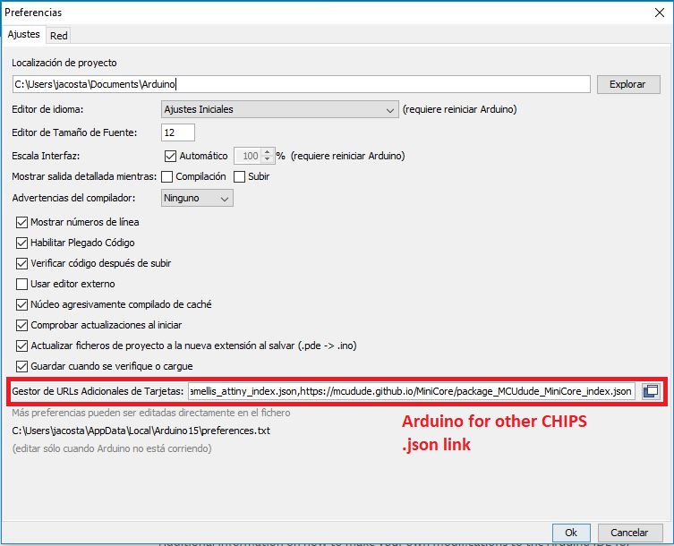
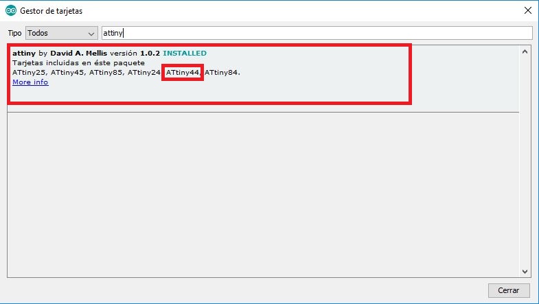
If you are new programming I recommend you to check the following guide, here you can improve or get programming skills. The Arduino IDE can be configured to program a variety of microcontrollers, not just the ones found on the standard Arduino boards. However, while this capability is possible for many other chips, not all have been documented. In the following link you can find some links that allow us to download some ATMEL Microcontrolers to work.
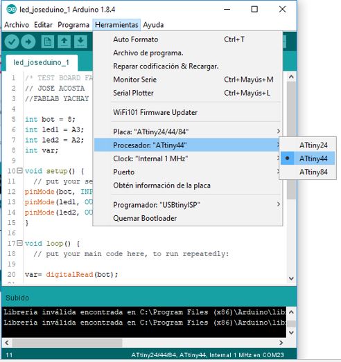
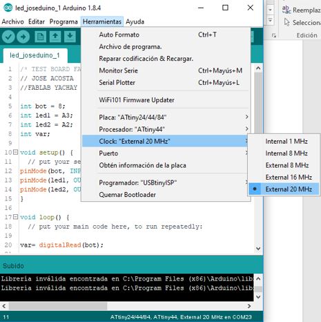
Once the configuration of the workspace is done, the programming of the plate's operation test created in the electronic design week is carried out.
When the program is compiled, the software creates a .hex extension of the program made in a system folder, which allows it to be loaded into the microcontroller, and can also be used in Proteus, which is an electronic simulation software.
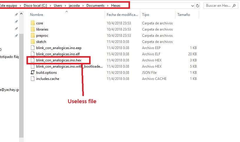
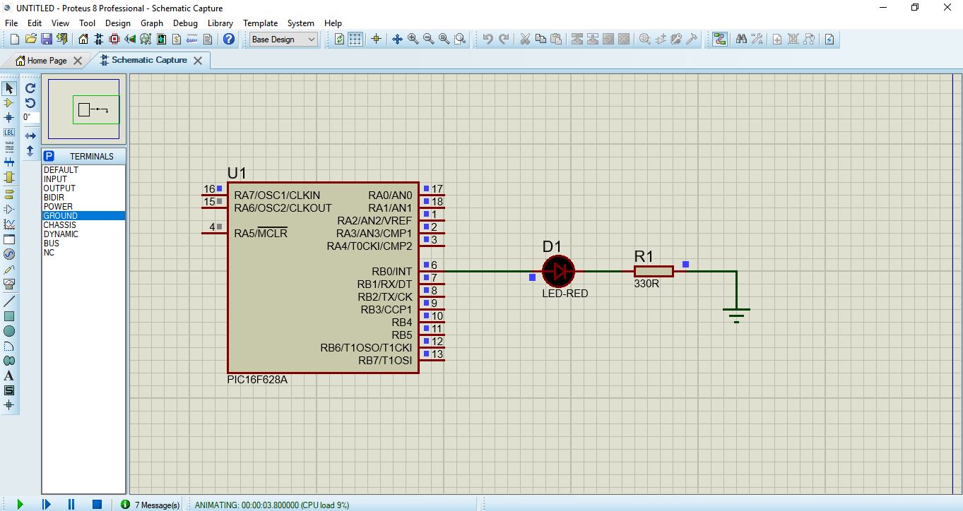
Now I am going to simulate the operation of the circuit with the microcontroller in the Proteus simulation software, for which I need to have the .hex file of the programming, created by the Arduino IDE, ready. To start with the activity it is important to create a new design scheme in Proteus.
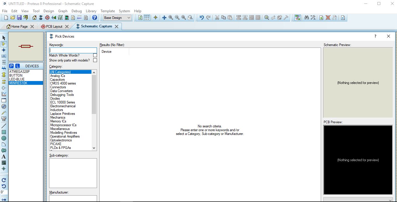
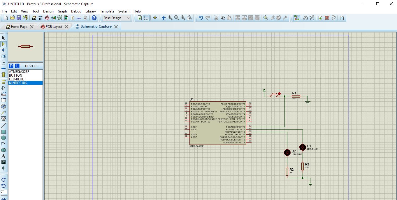
Then we look for each of the electronic devices in the software repository and leave them in the workspace and make the corresponding connections
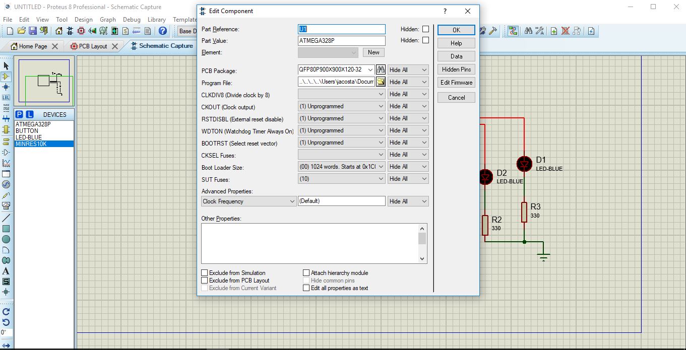
We give two clicks on the microcontroller to configure the operation options and load the programming made to execute the simulation.
SERIAL WRITE (HELLO WORLD)
BLINK
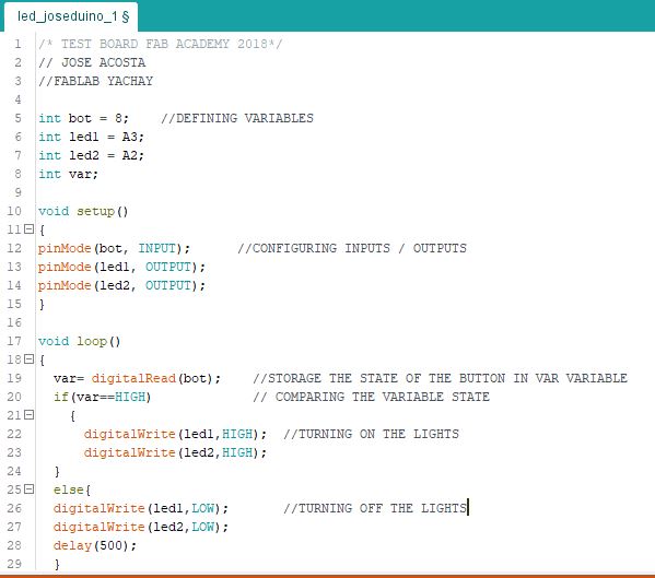
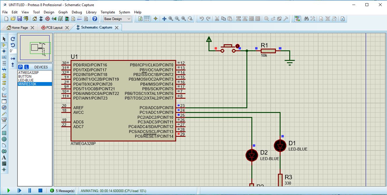
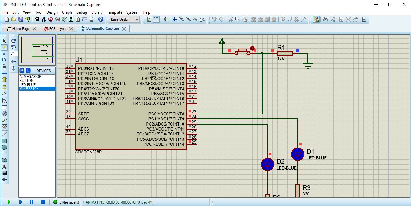
PUSH BUTTON AND LED
PUSH BUTTON AND TWO LEDS
EXTRA ACTIVITY
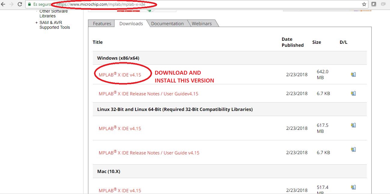
To complete this activity is important to install the MPLAB electronic programming software, you can download it from the following link, by default the language to program in this software is assembler but you can add other compilers, which allow programming in different languages.
To learn about assembler programming, I recommend following this tutorial to learn more about Harvard architecture and learn to program in assembly language
WHAT'S ASSEMBLER?
Assembly language is a programming language that is dedicated to writing low-level programs; let me explain a little about the low level programs because well a low level program is one that exerts extremely direct control of hardware, the word under refers to a reduced abstraction between what is language and hardware; the low level programs are made for controllers, specialized applications in real time, among others.
So we are saying that the assembly language is directly related to the machine code.
Where is the assembly language used?
The assembly language works directly with the microprocessor of a machine, that is, we program a microprocessor with this language, we can also use it to develop device drivers (Drivers) and computer operating systems.
MICROCHIP MICROCONTROLLERS
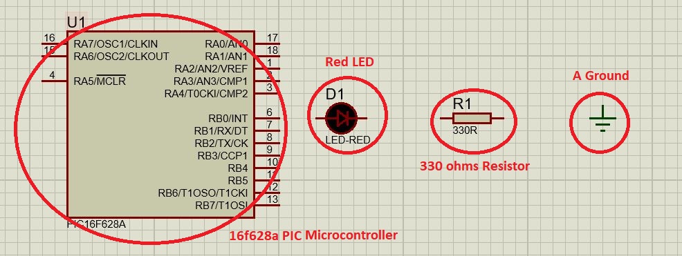
PIC 16F628A
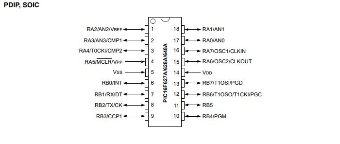
In the following link you can read in greater detail the datasheet of the microcontroller with which you are going to work
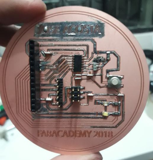
The present exercise is a blink with a red led, programmed in assembly language and simulated in proteus, when working with PIC microcontrollers we are using the Harvard architecture.
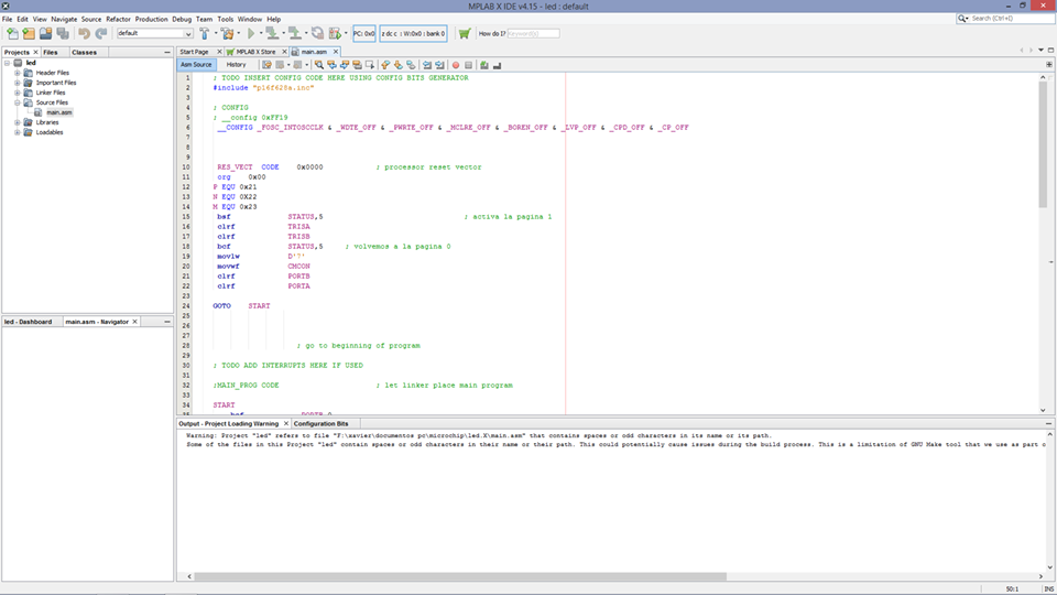
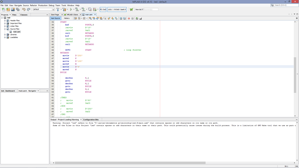
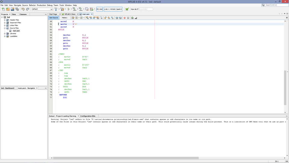
For this activity, we will use a PIC 16f628a microcontroller, a led, a resistance of 330 ohms, it is necessary to indicate that the programming made in Proteus will be simulated.