Show how I made and programmed the board
Explain any problems and how I fixed them
Include a ‘hero shot’ of the board
Show how I made and programmed the board
GROUP ACTIVITY
To perform the activity of the week, I reviewed information on how to create an AVR ISP programming board, referring to Zaerc's FabTinyStar tutorial
The machine that I will use for this activity is the Roland MDX-540 milling machine, with interchangeable tips, we start turning on the air compressor because the machine has pneumatic drive for the change of router bits and for the movement and the milling of electronic boards or figures in 3D using blue wax.
For this activity, the following electronic elements and materials will be used:
Materials:
Copper circuit board
Router bit 1/64 "
Router bit 1/32 "
Electronic Components:
1x ATtiny45 or ATtiny85
2x 1kΩ resistors
2x 499Ω resistors
2x 49Ω resistors
2x 3.3v zener diodes
1x red LED
1x green LED
1x 100nF capacitor
1x 2x3 pin header
a bakelite
You can buy some components in Amazon or in a local electronics components store
With all the elements ready for this activity, we will start calibrating the origins of the coordinates of the machine, for this we have two ways to calibrate the machine, the first is using the software of the machine and the other is with the manual control to locate the head and position the coordinates. In this case the calibration will be reactivated from the software.
To assign the coordinates origins, we will use the scroll buttons on the X and Y axes, manually locating the location that matches the copper board, then press the "Apply" button. Next to calibrate the Z axis, it is important to place the sensor on the height below the head (verify that the sensor is correctly connected to the machine), then press the "Start Detection" button, the tip of the head will touch the sensor and the system It will calibrate the height, it is important that the surface of the copper board is clean and totally flat.
It is important to designate the milling tip according to the activity to be performed, for engraving the electronic boards it is recommended to use 1/64 "tip and for cutting the board it is recommended to use 1/32" tip.
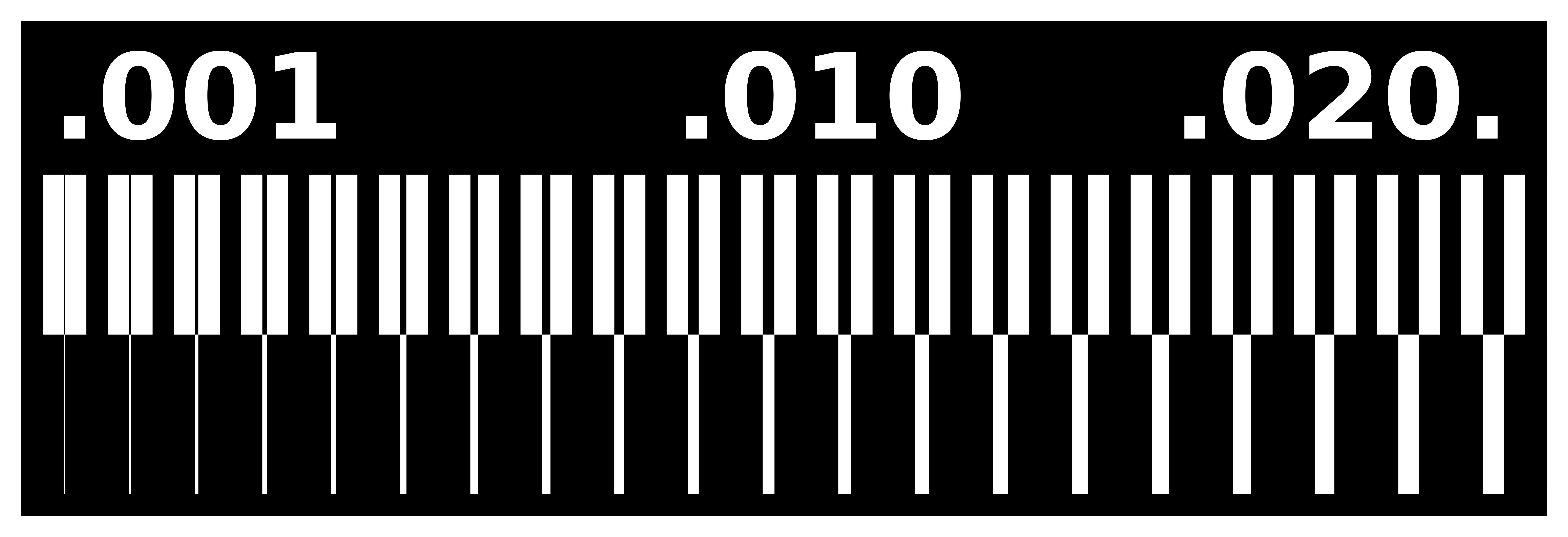
Before continuing with the development of the plate, it is important to verify the finish of the milling cutters of the milling machine with which we are working, for this, we will mechanize the following design, proposed as a group activity to be carried out.

Now, let's create the designed board, open the web browser and go to fabmodules website (click here to go there)
To start with the process of disvading, I started with the group activity loading the image .PNG in fabmodules, then making the following configurations according to the type of strawberry that we will use for this activity.
- PCB Traces: 1/64
- Machine: MDX-40
- Speeed: 2 mm/s
- x0: 3 mm
- y0: 3 mm
- z0: 0 mm
- Cut Depth: 0.15 mm
- Tool Diameter: 0.1 mm
- Number of Offsets: 1 mm
Then its ready to mechanize, so is important to machine our design on the machine to check the definition of the machine for this activity and have conclusions.
The result of the machining of the group activity is the following:
It can be seen that the engraving is of quality and exact, there is no variation in the engraving, nor damage to the board
The machining process from the software will be detailed in the following activity, indicating all the considerations that must be taken at the time of performing the activity.
We start important design with .png extension to convert .rml extension and can mechanize
Now we are going to carry out the same activity but to cut the electronic board, we must configure the milling tip to 1/32 ", in the fabmodules webpage we will perform the same previous activity but we will select the following parameters that are shown below.
Once with the generated files, we load them into the engraving software, and proceed to mechanize them.
The surface of the electronic board must be attached to the base with double-sided adhesive tape.
Is important to remove the parts
Then is important to sold the electronic componets to the board using soldering, tin, welding ointment and a multimeter to verify the connections
INDIVIDUAL ACTIVITY
Now start the real activity to the week, I'm going to charge the firmware to the programmer to get their completly functionability, I'll be refer this tutorial to do this activity "Using the GNU AVR toolchain on Windows 10". For this activity I will use this element:
ATMEL - ICE (Click HERE TO SEE THE DATASHEET).