PARAMETRIC DESIGN
First I will design two elements on Rhinoceros, using Grasshopper complement
ADVANTAGES OF USING RINHO GRASSHOPPER
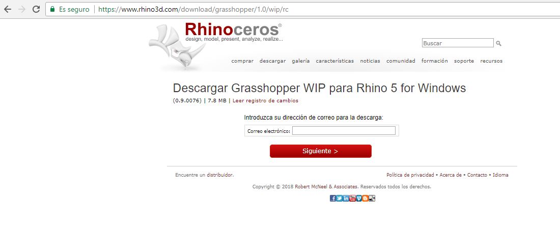
To start the actvity let´s download and install the software, You can download ans look for some design information in its webpage (clik here).
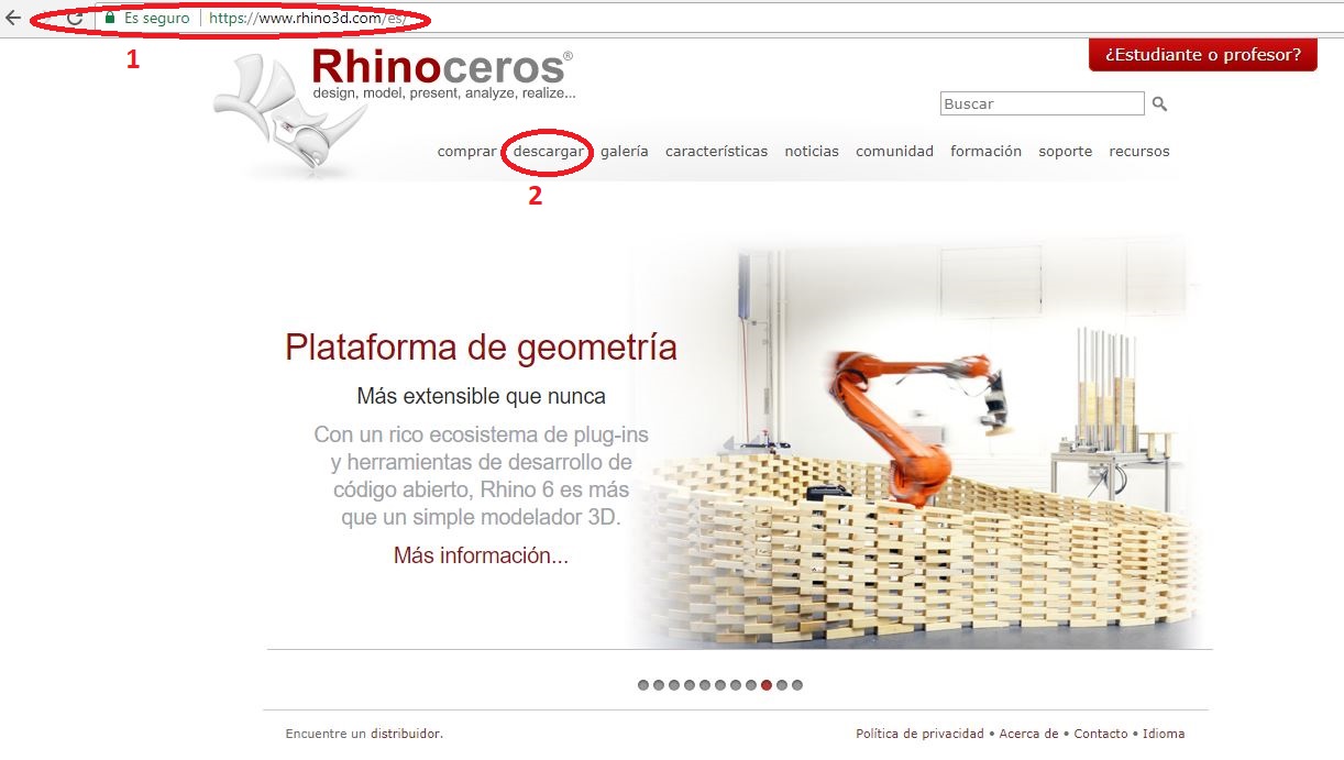
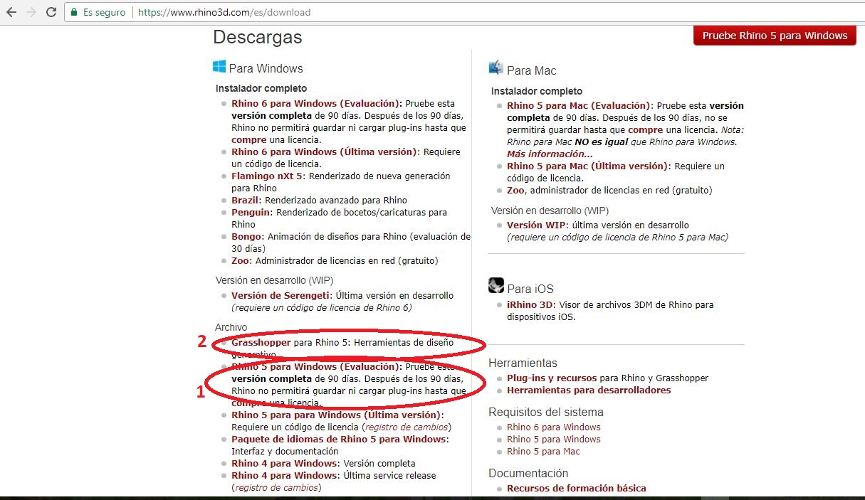
Is important to download Rinho software first an then Grasshopper complement. We will use evaluation software, we'll have 90 days to test for designing, then let's download the complement, to download every option let's register our e-mail, and then get the files.
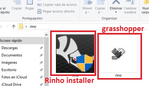
Once we have the softwares, we need to install Rinho first ant then Grasshopper, its simple to do this, select the default options and install.
Design 1
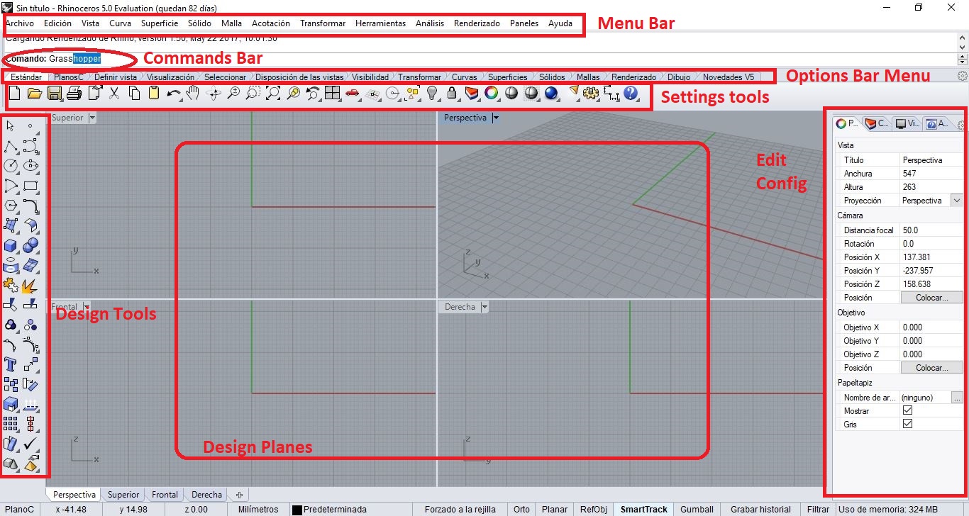
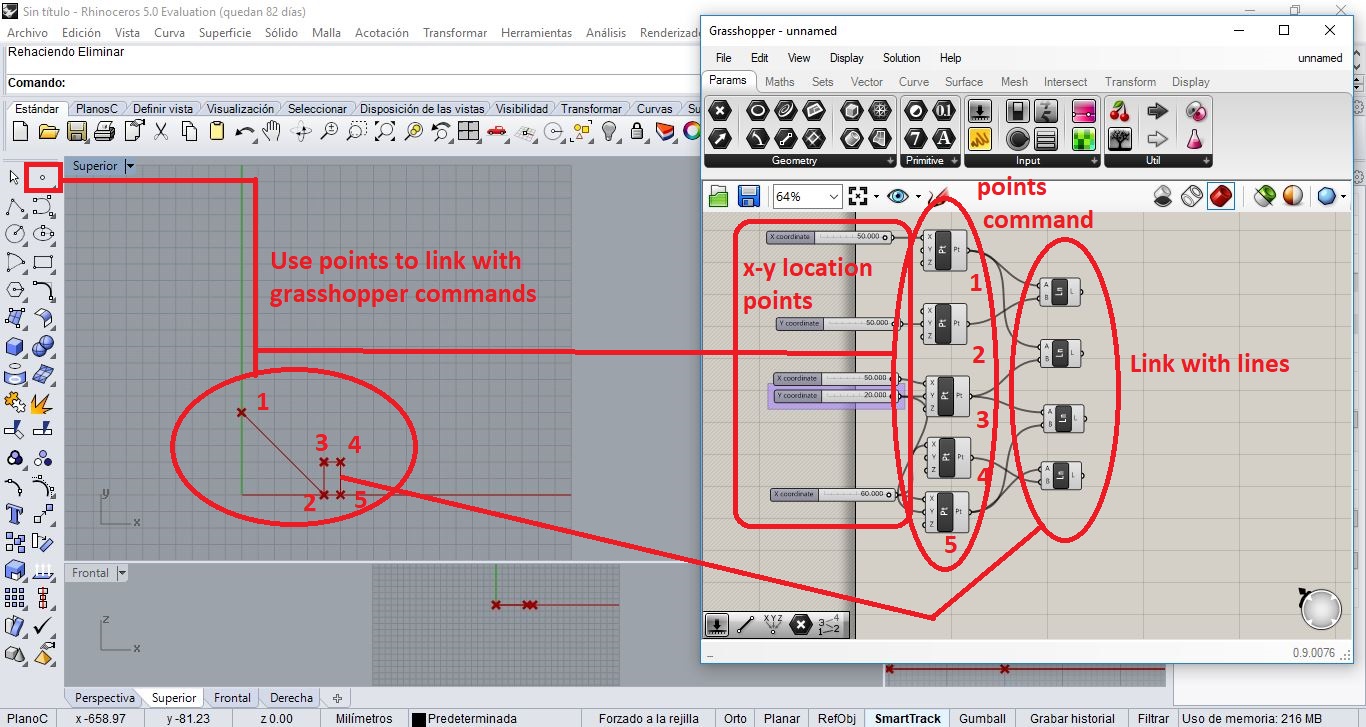
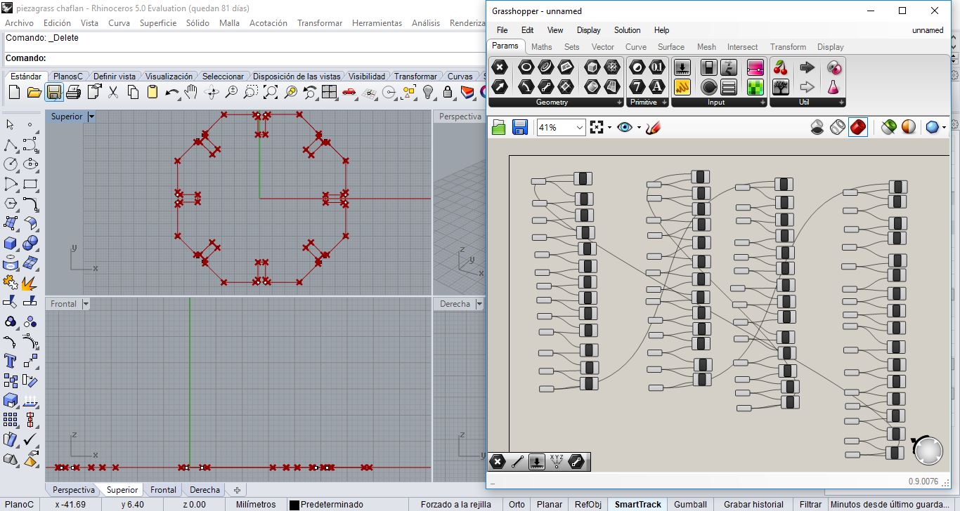
Let's open Rinho, in the command bar need to write grasshopper to open the complement window.
Then, this window will open:
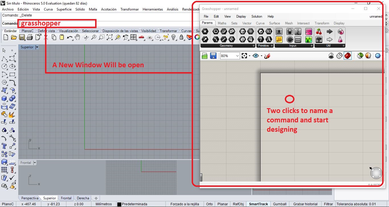
Let's design some parametrig element to test the software.
To do this I suggest to you just probe all the design rinho and grasshopper options
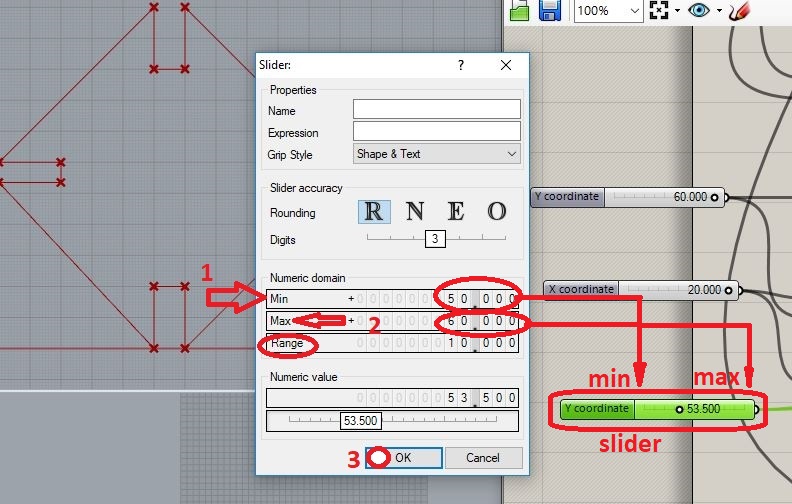
Now I can customize the length of each line to modify the parametric design or I can replicate the design as many times as I want, also I can configurate its extrusion
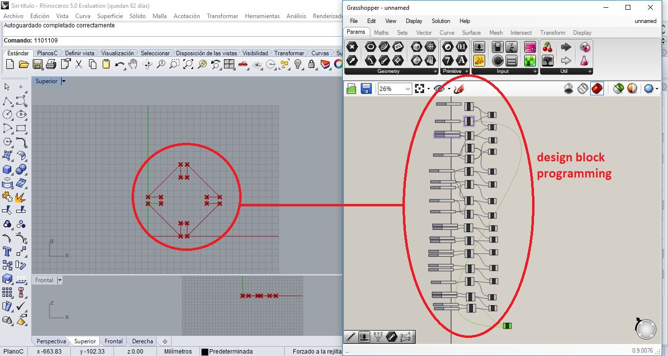
Lets see the following GIF with a short demostration of the parametric setting of our design.
Design 2
I have designed another element a little complicated to test the program doing parametrics
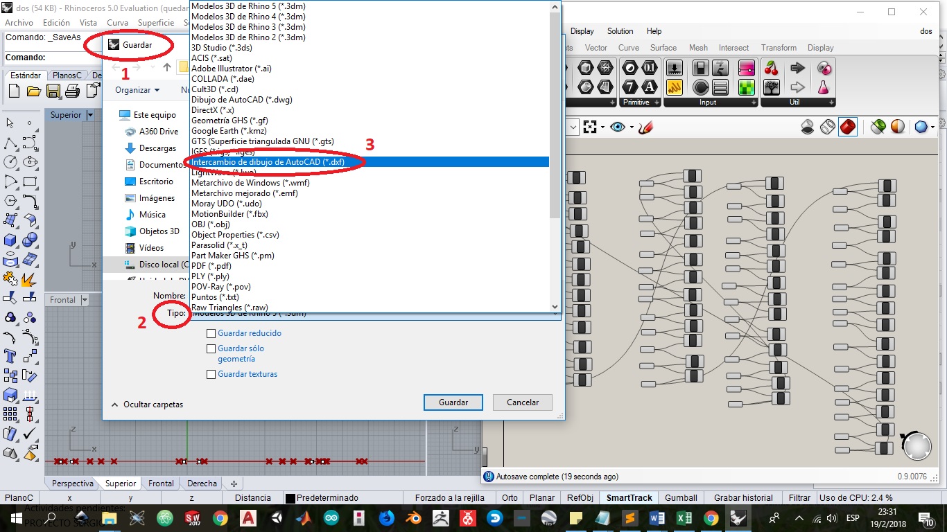
Then, I'll save the design on dxf to cut in laser.
To practice in this software I have learn tricks and concepts in this PDF Tutorial: PDF
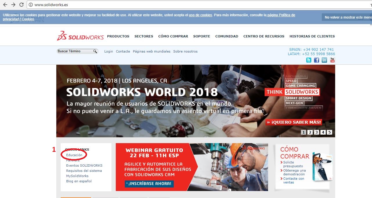
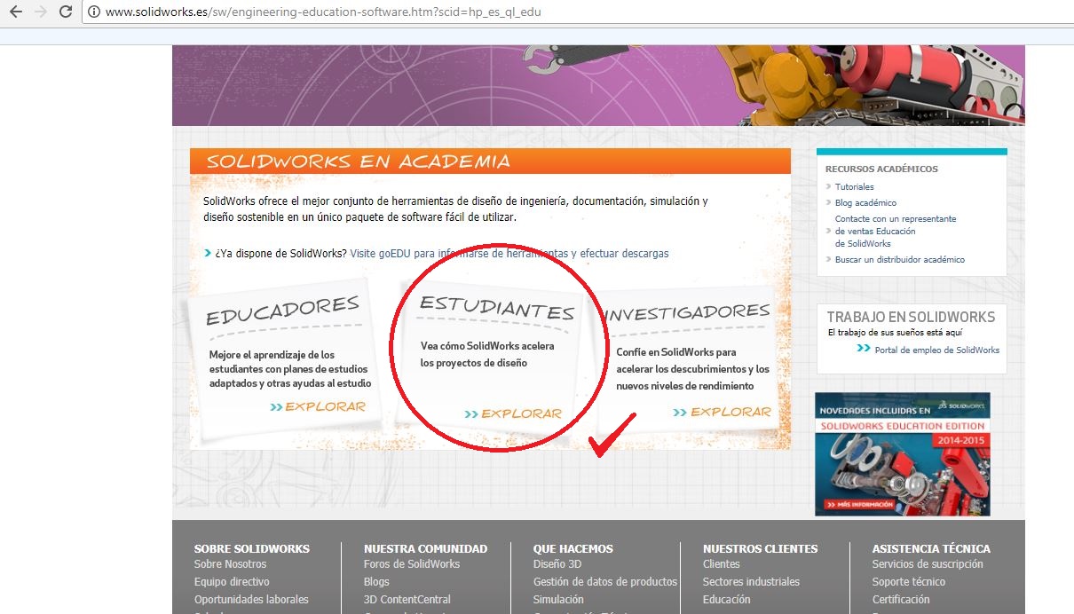
Another alternative parametric software is SolidWorks, it´s a software that allows customize design measures. You can visit its page here and find more information.

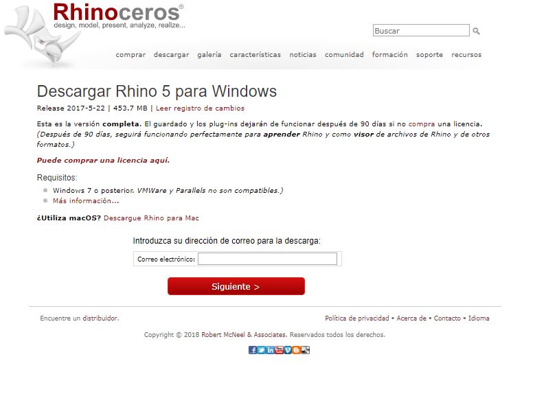
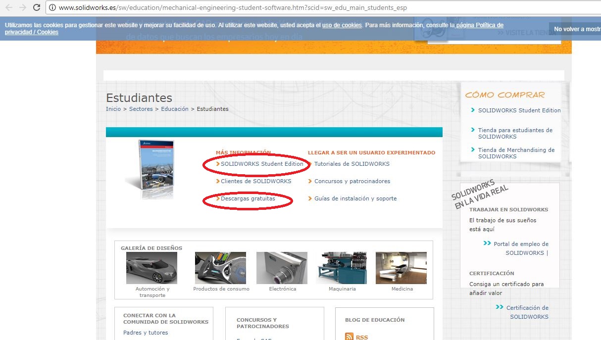
First, let's install the software, for this we need to open the software webpage
I recommend you to download the educational version software for research, you'll have a trial evaluation software to design
Once the software is installed, let's design
I have some experience designing in SolidWorks but allways I need to remember something, to practice I have learn using Youtube tutorials
Click here to find some Solidworks Tutorials on Youtube
Then let's start with some designs of the parametric kit:
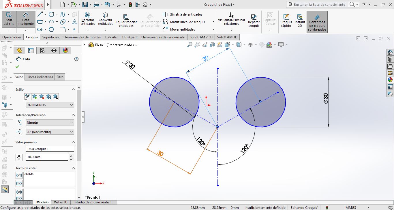
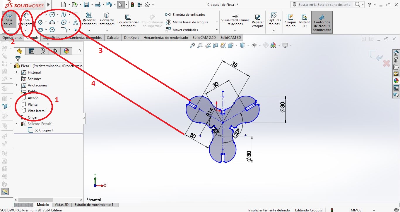
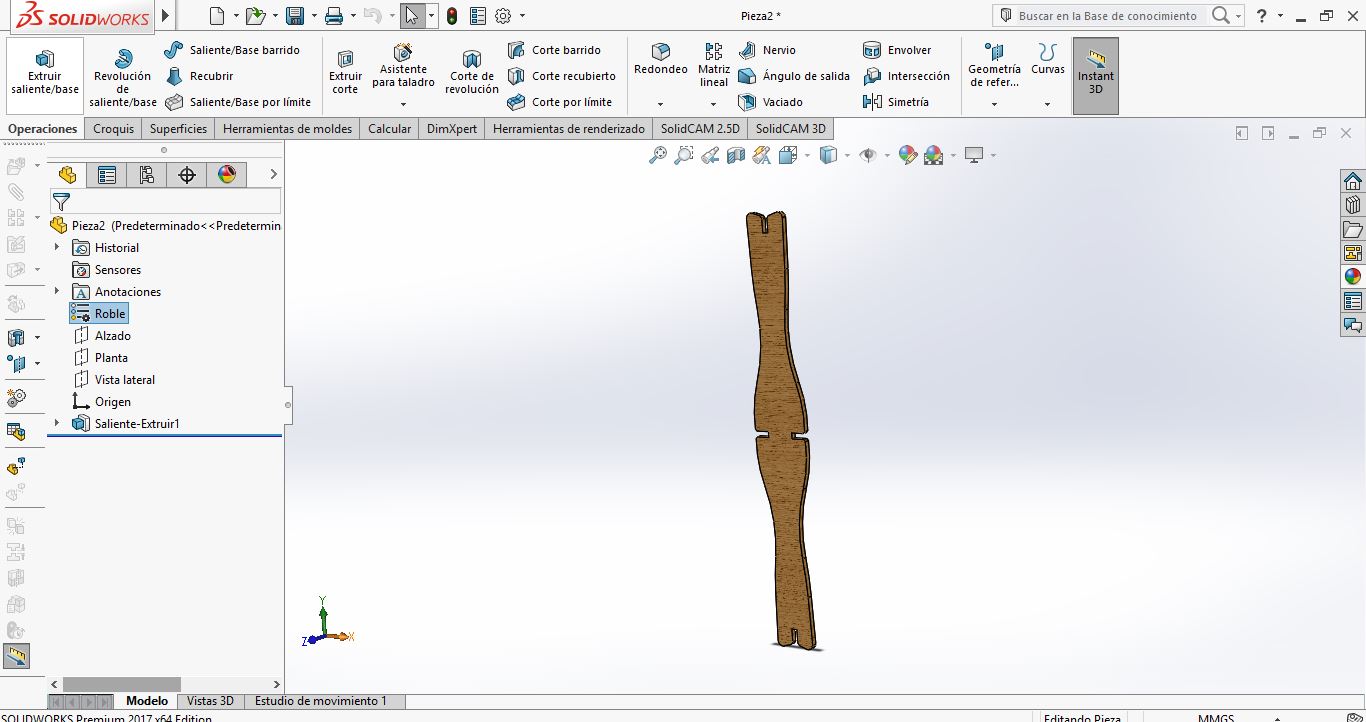
Let's Open the software and then select a piece design option to start, I'll select front view and will create a sketch in 2D
Then, using the drawing options I have design this elements:
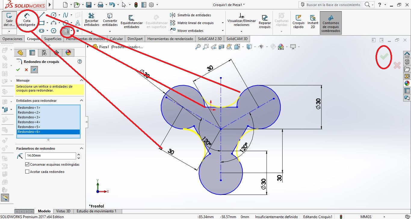
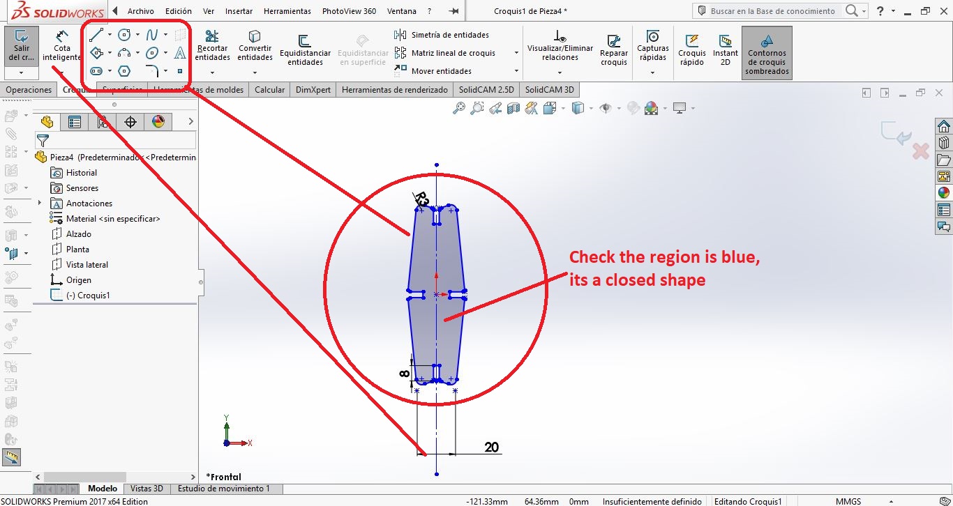
When we have a design totally closed, the region turns on blue, and it let us extrude the design as well as we want.
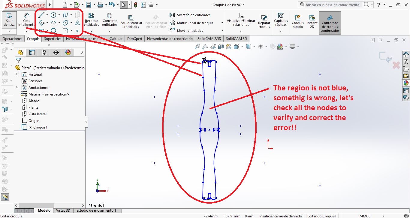
Sometimes, the regions are not closed totally, it is a problem becouse the design cant be extracted.
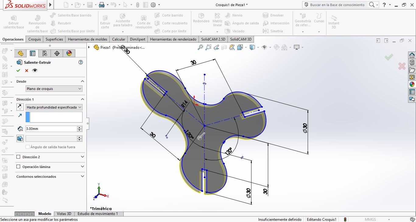
But in this case, we have correct all the design problems and have extruct all the design according of the thickness of the material to be used in this activity
.
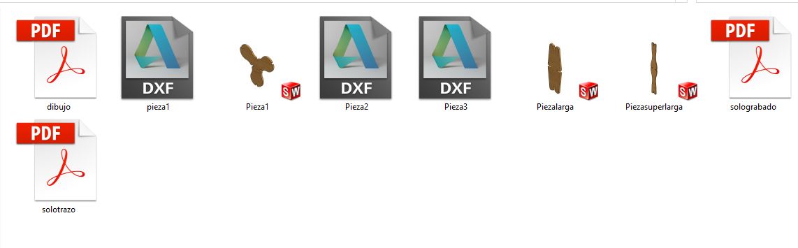
Then, I need to save the designs as .dxf file to be cut in laser
Some cases is important to configure a file to cut with our designs, for my activity I have used Inkscape to configure mine
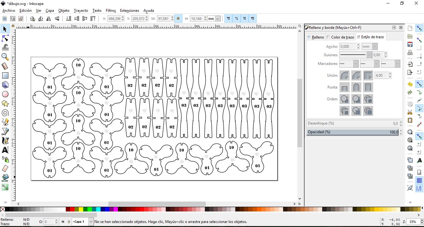
To cut these parts it is important to create the types of files, one that corresponds to the cutting line of the pieces and another that corresponds to the engraving of the material.
When cutting is important, first the engraving is made and then the cutting of parts, to prevent the engravings from moving.
GROUP ACTIVITY
The cutting and laser engraving are based on a series of parameters that must be established, to achieve the effect we want to obtain in each material with which we want to work. The parameters vary according to the type of material (plastic, wood, etc).
You can only get perfect results in engraving and laser cutting if it is correct when choosing the parameters. The laser parameters are a combination of the following configurations:
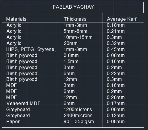
How to set the kerf in materials
In activities of cutting and laser engraving it is important to take into account the cut of the design, adding or subtracting the width of cut of the dimensions of its external part. The following table shares an overview of the average laser measurement that will be lost when cutting materials according to the thickness of the material. The information presented should be treated as a guide.
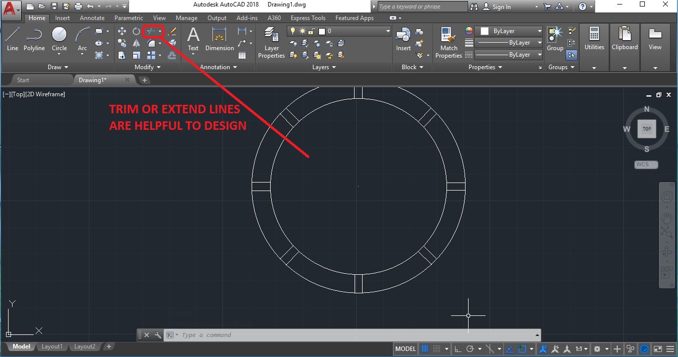
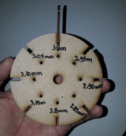
As a group activity, Yachay Team have designed a press fit as a useful tool to ensure the fit of the material, this design was propoused by Eduardo Cartagena, In this case I have used AutoCAD to replicate the design.
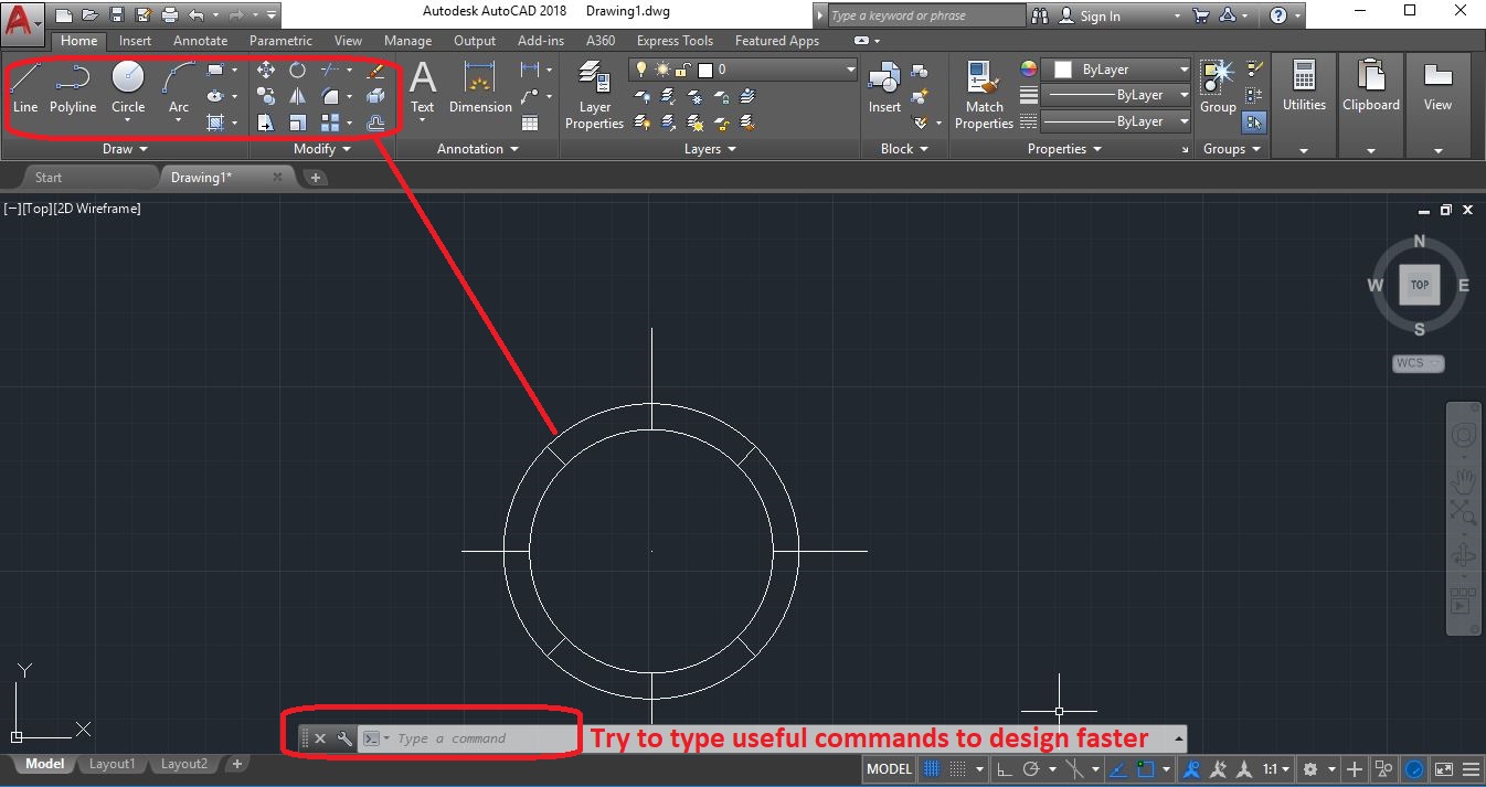
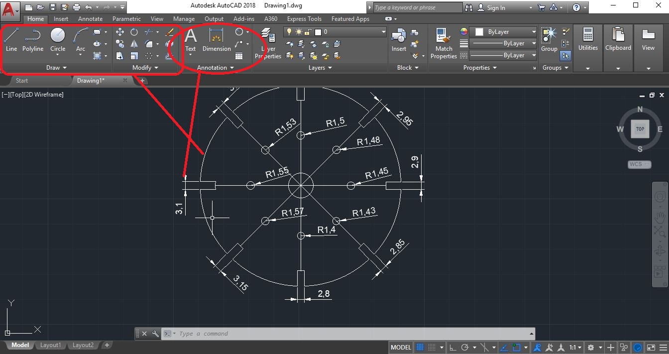
The dimensions of the fit holes of the press fit were: 3mm, 2.95mm, 2.90mm 2.85mm, 2.80mm, 3.05mm, 3.10mm, 3.15mm.
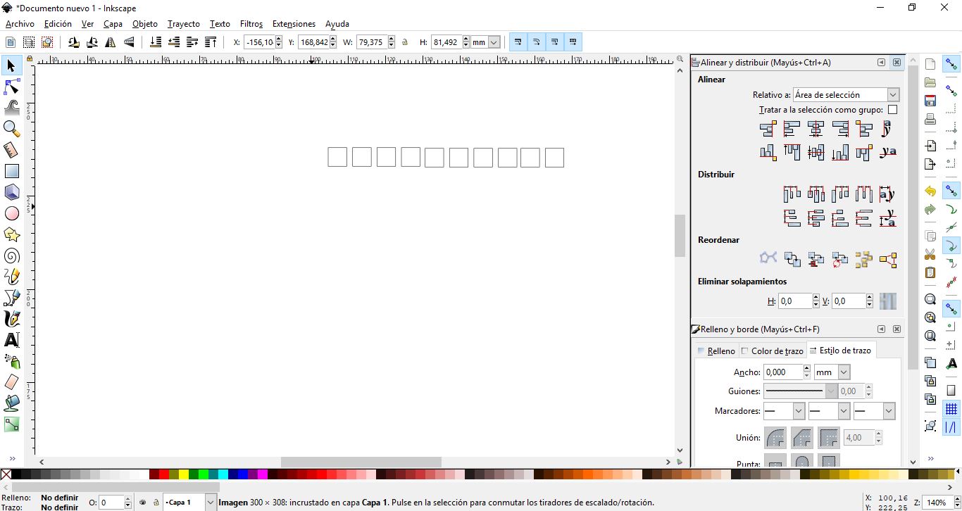
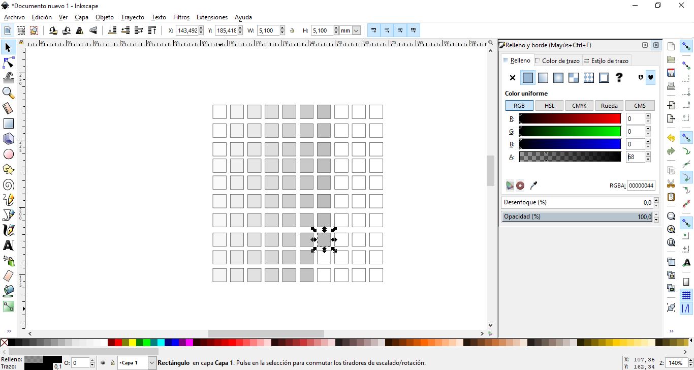
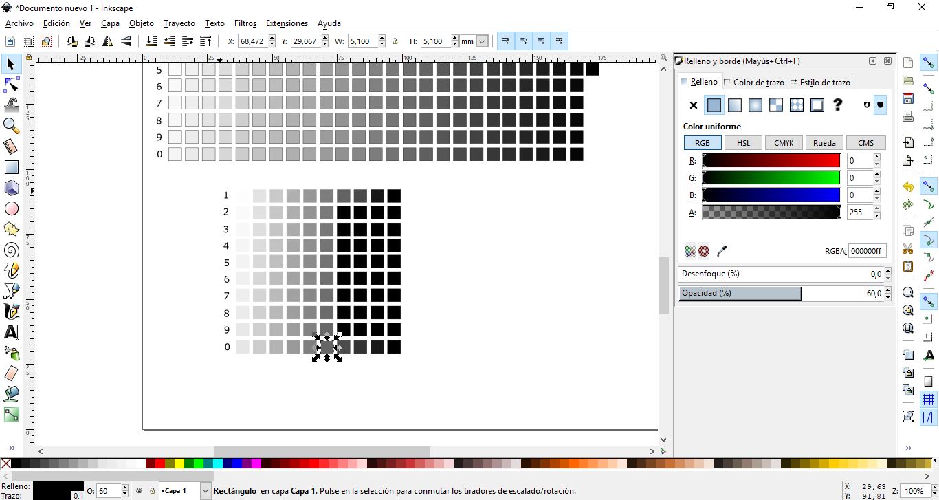
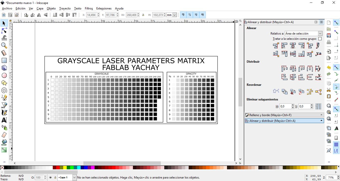
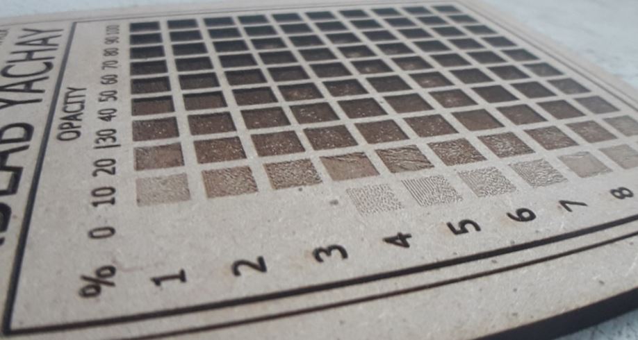
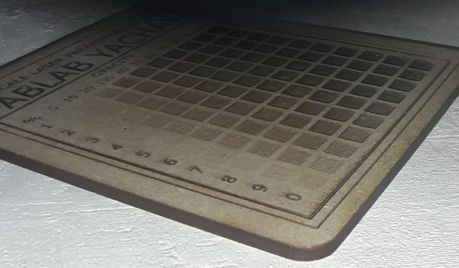
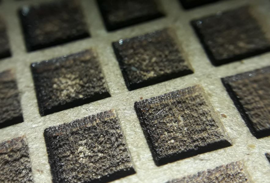
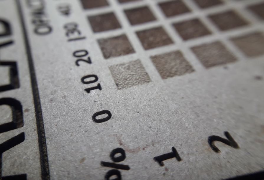
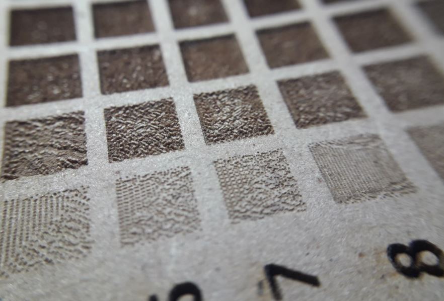
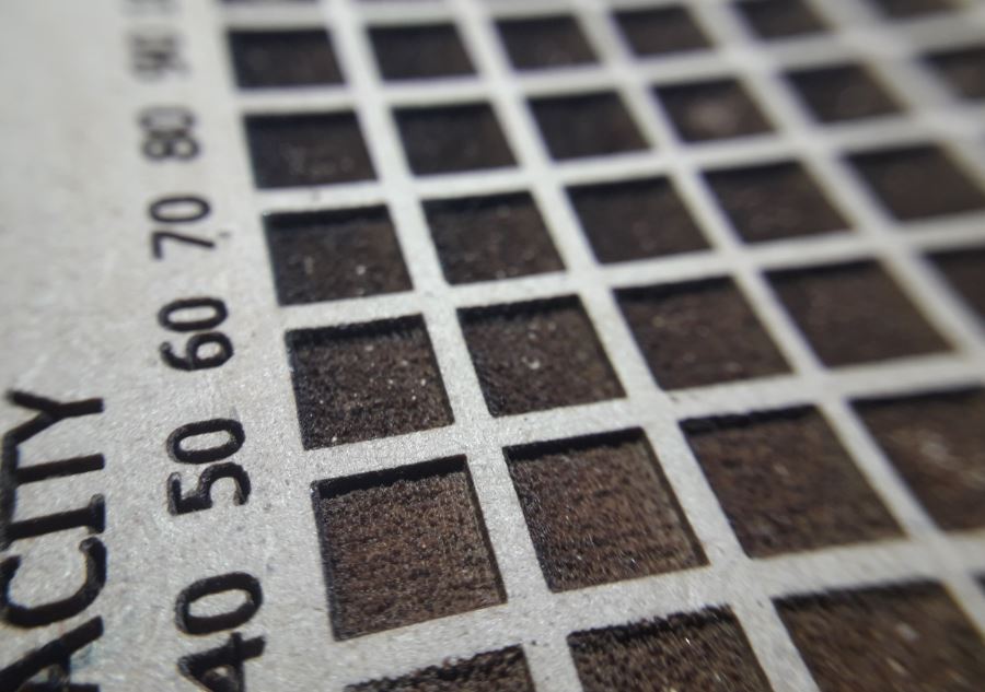
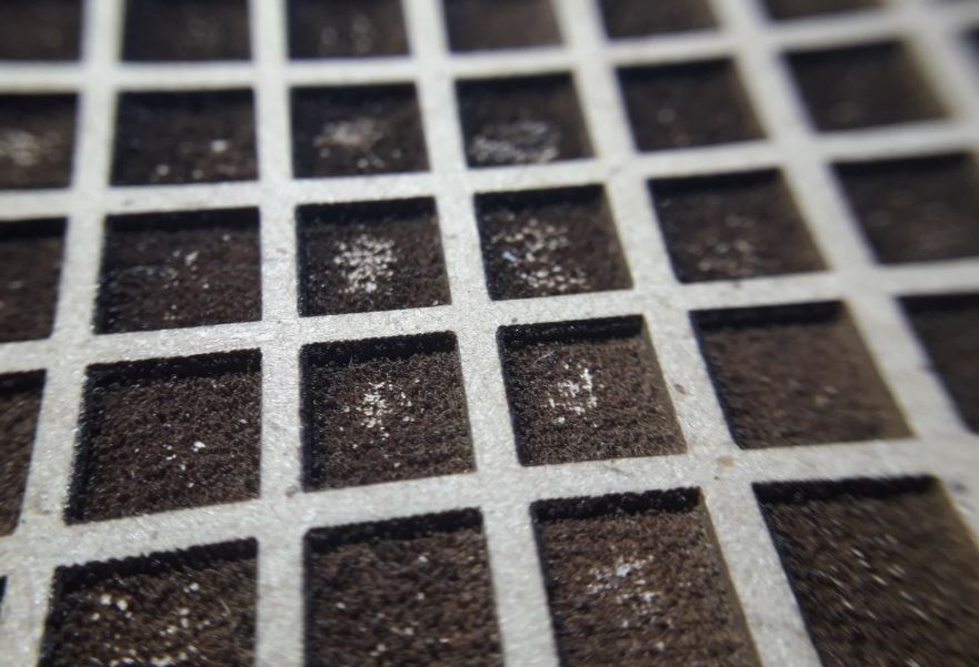
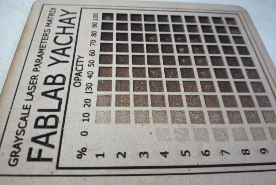
Further, I have designed this grayscle laser matrix parameters to help us to configure the laser power when we will engrave some design on materials. (Inkscape used for this)
LASER CUT ACTIVITY
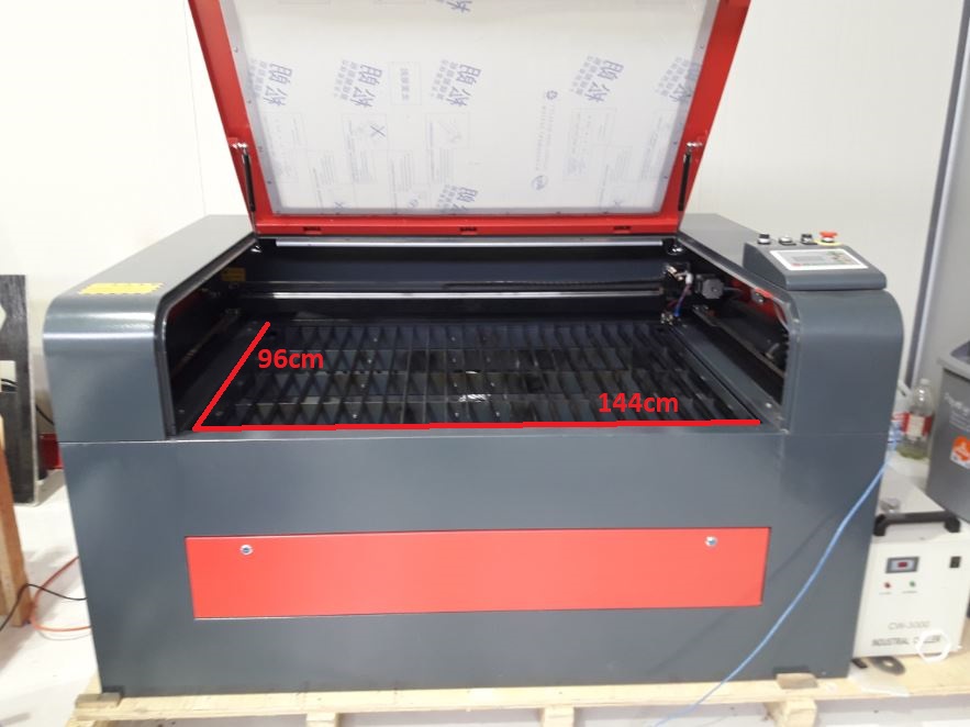
Our laser cutter is manufactured in China and has the following specifications:
More information in this link. The working surface of 144 x 96(cm).
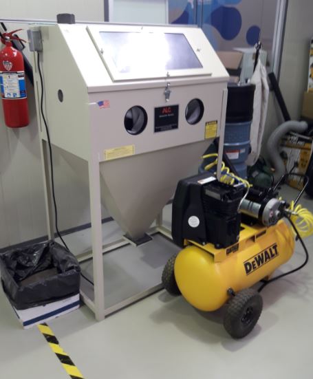
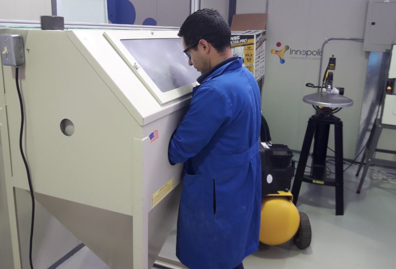
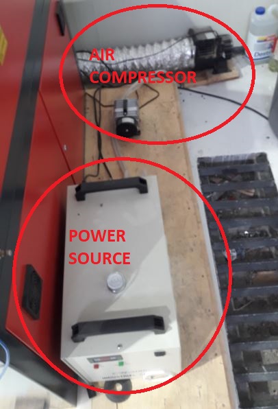
1.- Is important that our design will fit in the work area. To start using the machine is necesary to power on the air compresor and the power source.
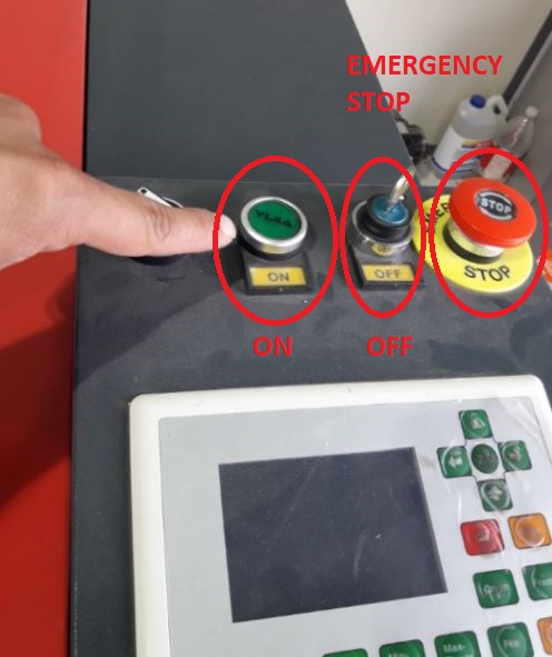
2.- Then I power on the machine using ON Botton, if something goes wrong there are two bottons one for emergency stop an a power off security switch.
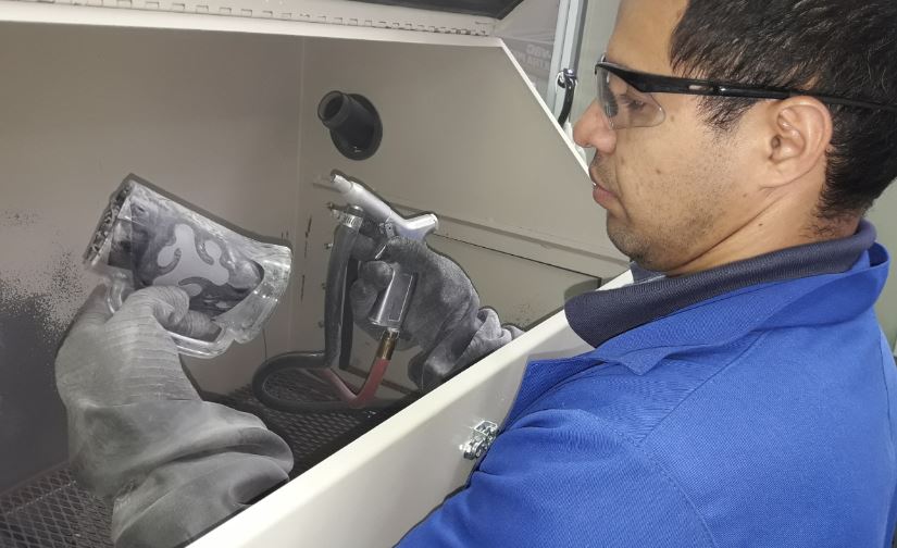
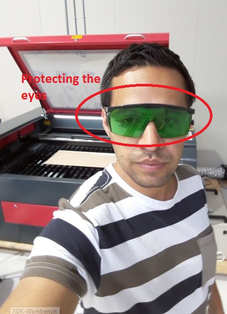
3.- I must wear protective glasses and avoid to see direct to the laser while it is working.
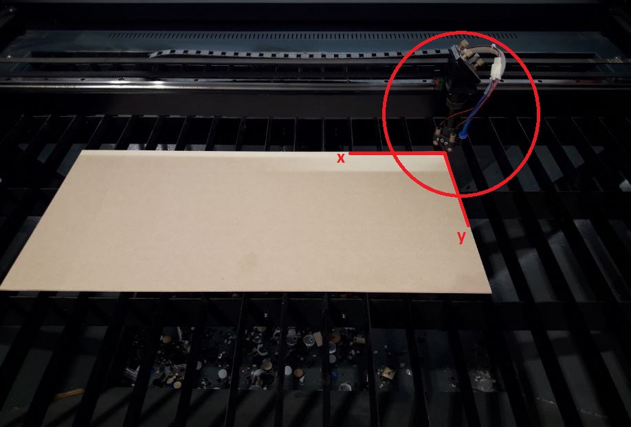
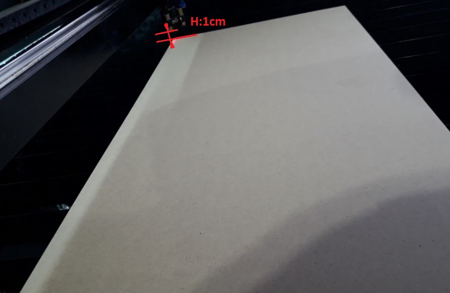
4.- Let's configure the zero axis origin on laser cut surface, using the lights that come out from the laser head, the recommended height to configure Z axis is 1cm from the laser output to the surface of the material to be used, to do this activity we will use 3mm thick MDF wood.
We could use these materials if won´t have MDF wood:
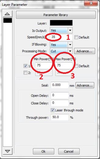
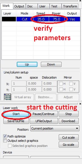
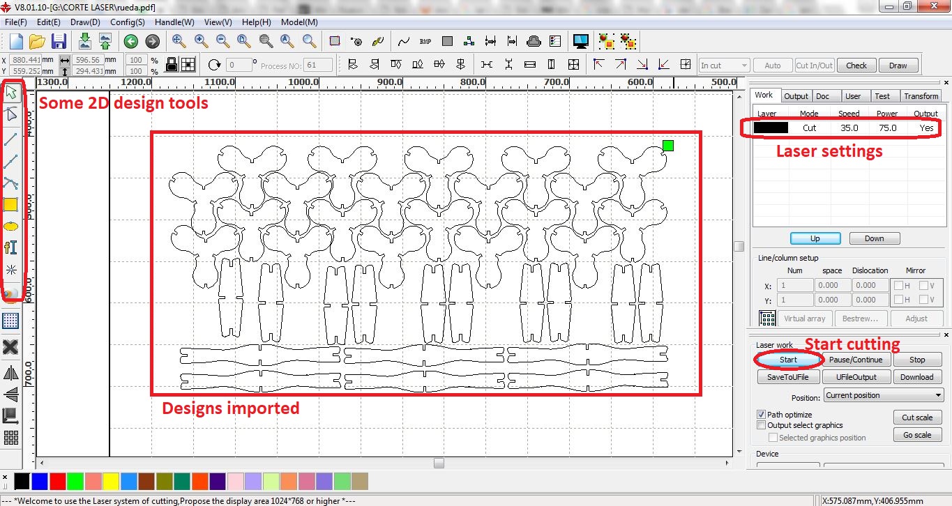
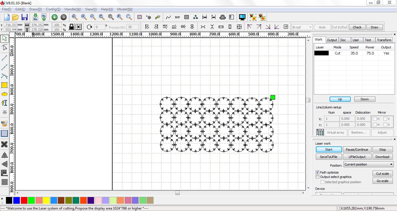
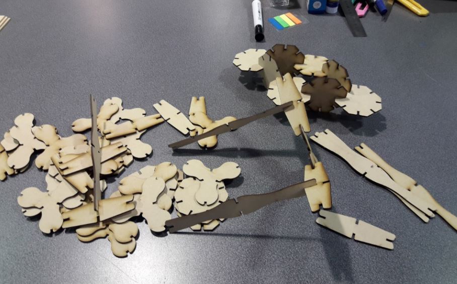
5.- I'll open the laser cut software, then is important to import the .dxf design and configure the number of parts, dimensions, cutting power and engraving, speed, all this depending on the thickness and the type of material that we are going to use. We need to set the origin in the software too as a reference to use the work area. For this activity I´ll set the following parameters:
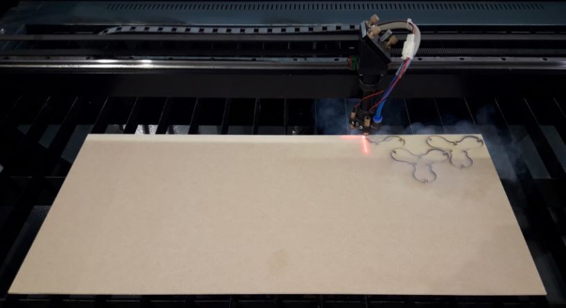
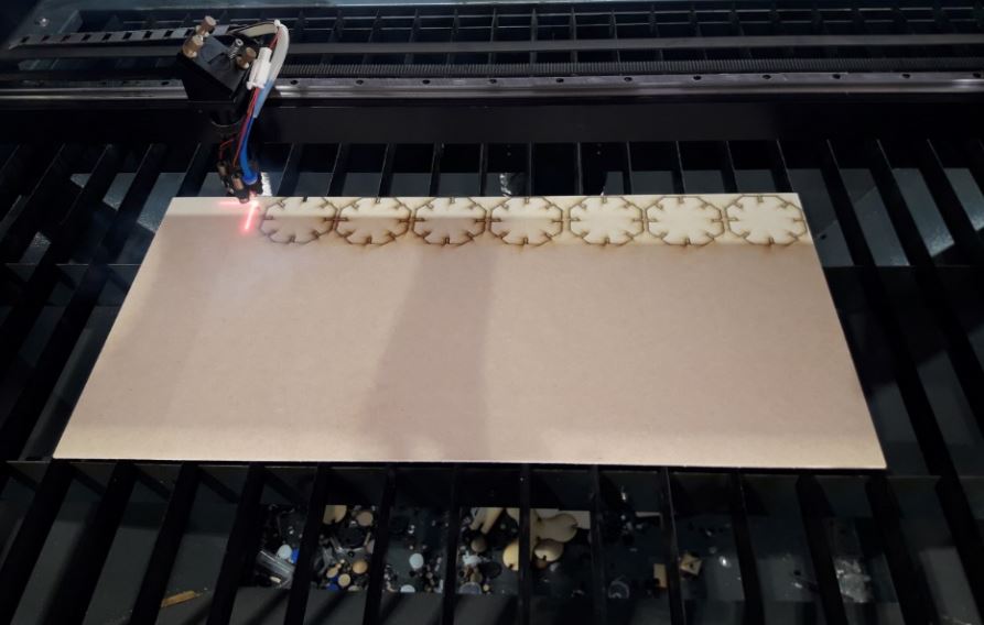
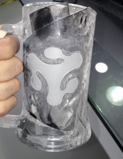
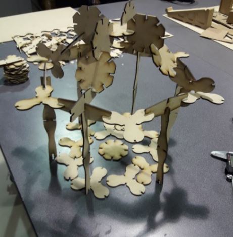
6.- The result is this, I have the pieces cut, it's time to assembly any structure to complete the activity.
In FabLab Yachay we have another additional laser cutter, it is the 40 Watts ZING EPILOG 24 Laser cutter, with a working area of 60cmx30cm and a configurable thickness according to the activity you want to perform.
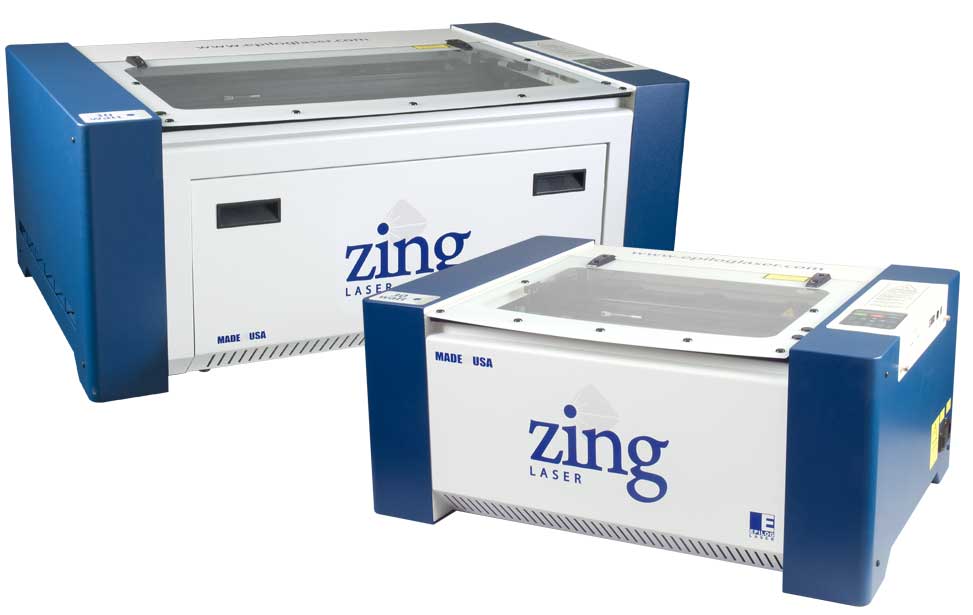
This machine has the following specifications:
More information here, I will use this machine for next activities
VINYL CUT

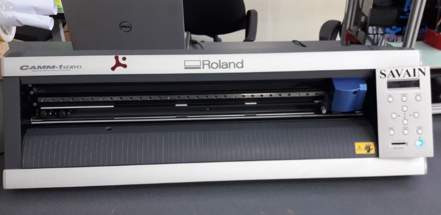
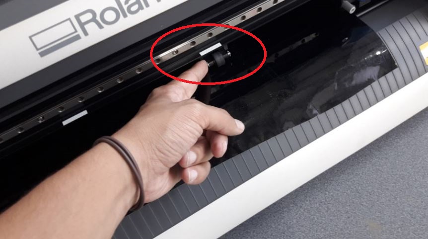
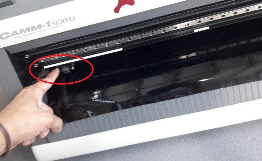
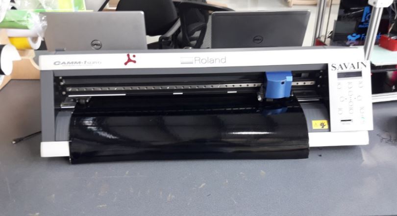
For the vinyl cutting activity, I used Roland CAMM-01 cutting plotter with interchangeable blades, this machine can cut into rolls of vinyl with this dimension: width: 55cm - long: 120m.
More information about the vynil cutter, pls click in the following image. ![]()
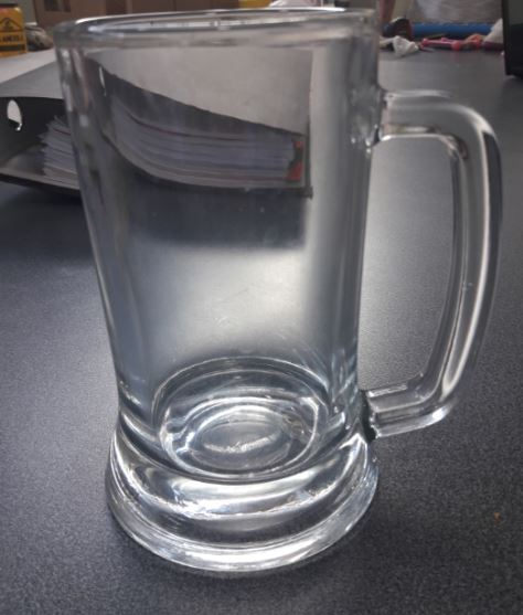
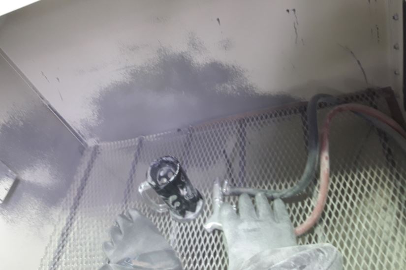
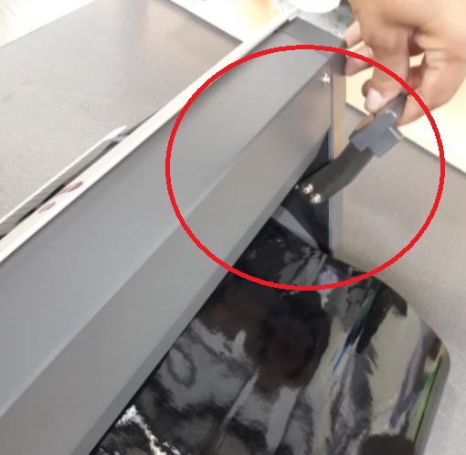
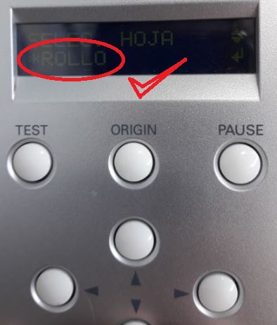
To start with the activity this week it is important to configure the assembly of the material in the machine, I selected the black color roll vynil to print the designs and a piece of transfer paper
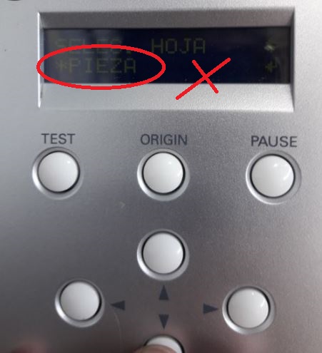
Once ready, let´s start with the design.
In the previous week, we designed 2D models that we can cut in this week. We look for an image that we like on the internet, always assured that there is no brand or design protected by an author, the design can be made by us if necessary.
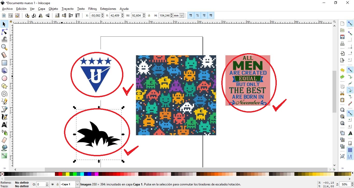
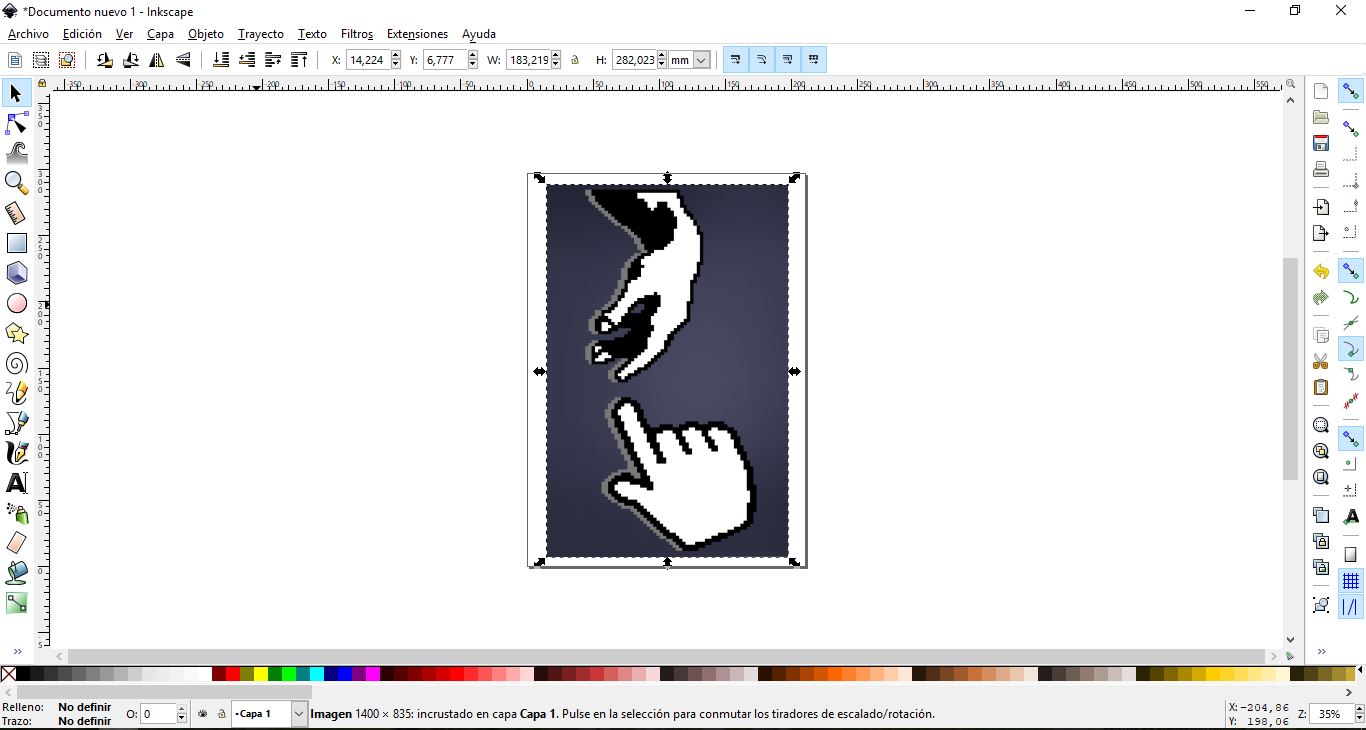
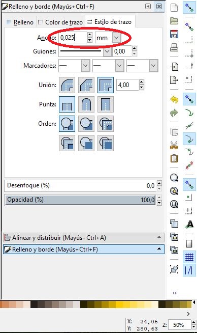
Once we have designed the sketch on inkscape, we save it in pdf, with the following configurations: Thickness of the route: 0.025 m (if not, double-cut plotter traced)
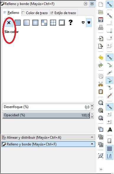
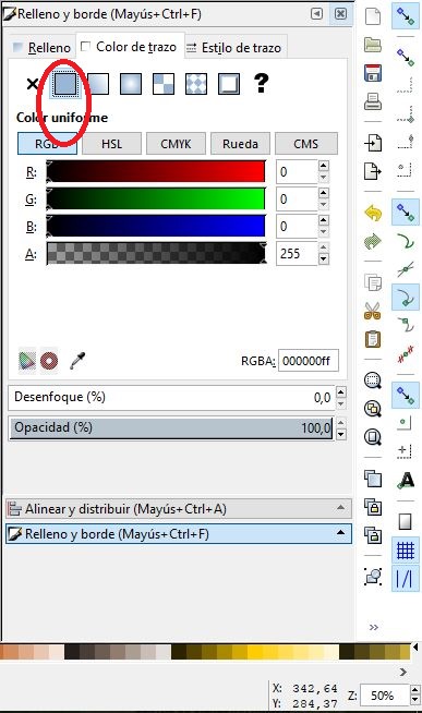
Remove fill from designs Mark the black trace
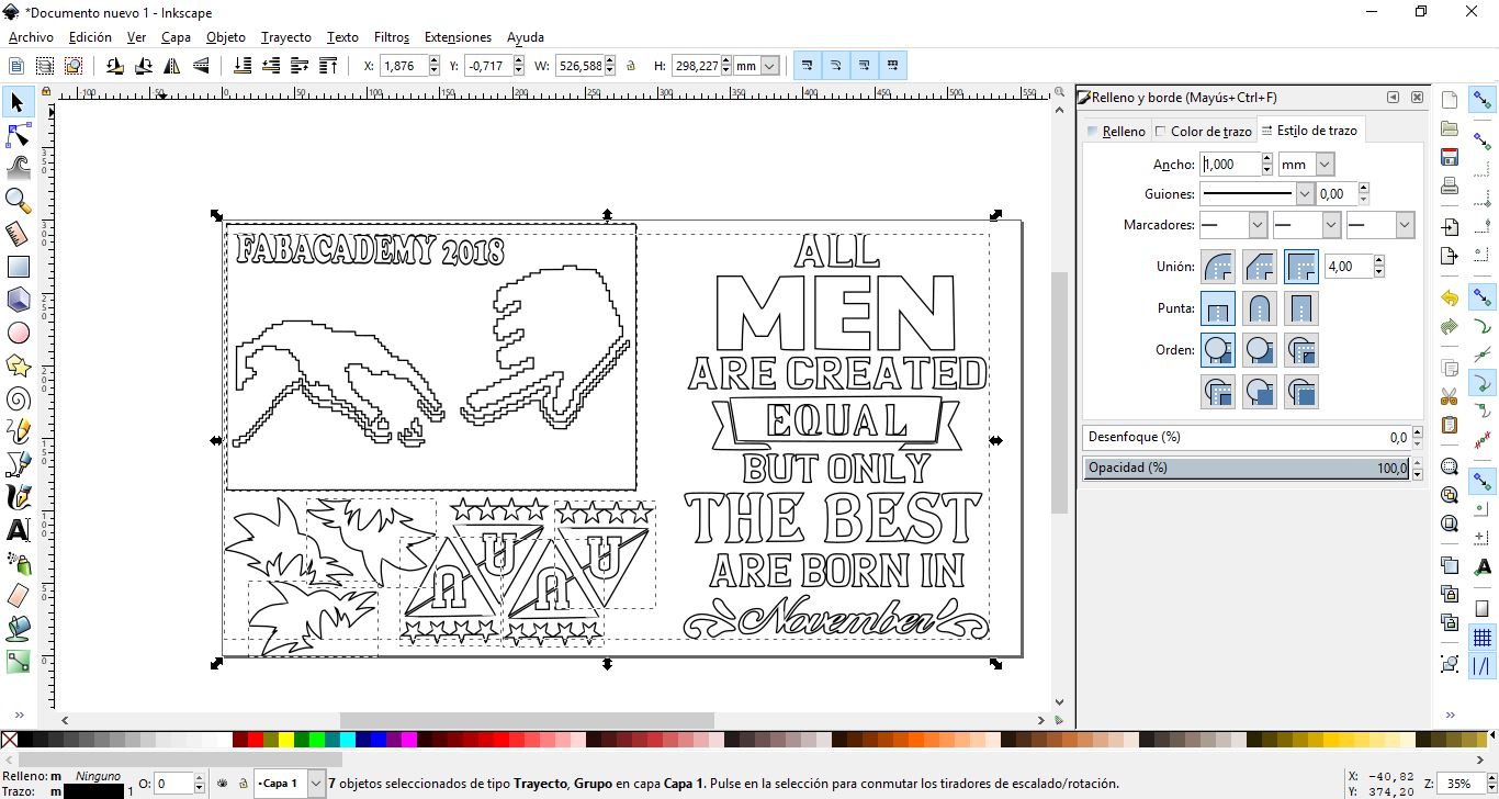
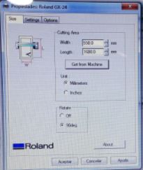
When cutting, we must configure the specifications of the plotter that we are going to use and adapt the design made to these measures so as not to waste material.
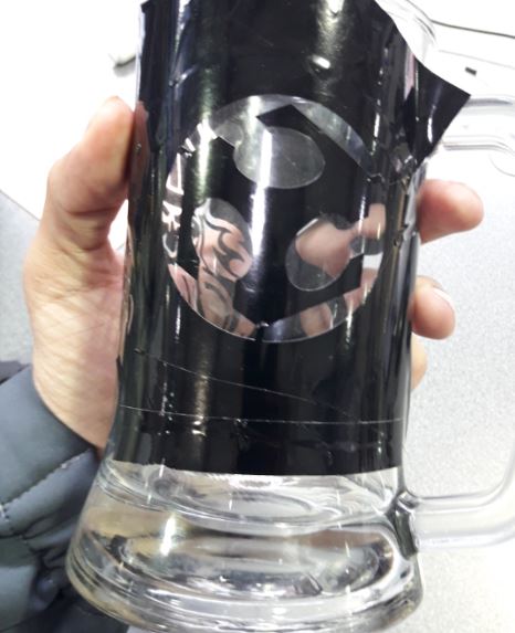
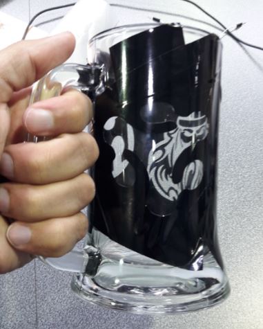
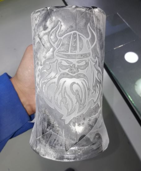
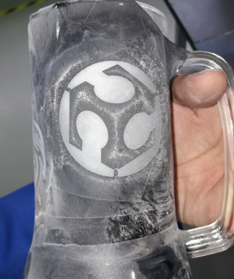
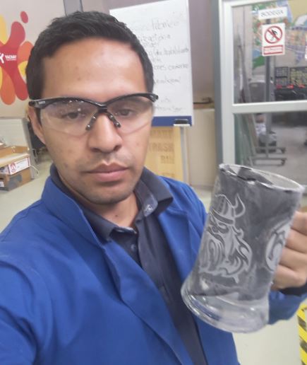
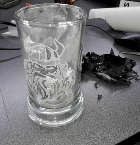
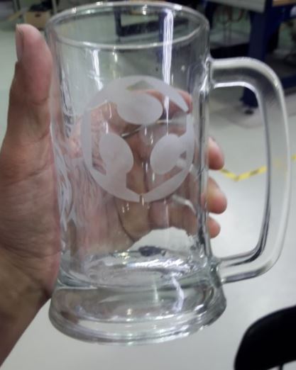
We send to cut the vinyl and we observe how the cutting of our design is carried out, until it is finished. And we have the following result:
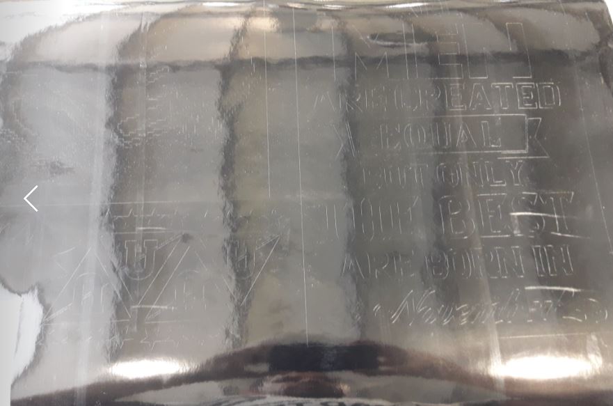
To stick the designs on surfaces it is advisable to use paper transfer, with this we avoid that our designs stick improperly on the surfaces.

EXTRA ACTIVITY