COMMUNICACTION PROTOCOLS
TCP/IP
TCP / IP stands for Transmission Control Protocol / Internet Protocol (Transmission Control Protocol / Internet Protocol), a system of protocols that make possible Telnet, FTP, E-mail, and other services between computers that do not belong to the same network.
The Transmission Control Protocol (TCP) allows two hosts to establish a connection and exchange data. The TCP guarantees the delivery of data, that is to say, that the data is not lost during the transmission and also guarantees that the packages are delivered in the same order in which they were sent.
The Internet Protocol (IP) uses addresses that are a series of four or eight (byte) numbers with a decimal point format, for example: 69.5.163.59
Application Protocols such as HTTP and FTP are based and use TCP / IP.
UART
UART (universal asynchronous reception-transmission) is one of the most widely used serial protocols. Most microcontrollers have UART hardware. Use a simple data line to transmit and another to receive data. Commonly, 8 data bits are transmitted in the following manner: one start bit, at low level, 8 data bits and one stop bit at high level. UART differs from SPI and I2C in that it is asynchronous and the others are synchronized with a clock signal. The UART data rate is limited to 2Mbps
SPI
It's another very simple serial protocol. A master sends the clock signal, and after each clock pulse sends a bit to the slave and receives a bit from it. The names of the signals are therefore SCK for the clock, MOSI for the Master Out Slave In, and MISO for the Master In Slave Out. To control more than one slave it is necessary to use SS (slave selection).
I2C
The main characteristic of I²C is that it uses two lines to transmit the information: one for the data and another for the clock signal. A third line is also necessary, but this is only the reference (mass). As circuits are usually communicated in the same plate that share the same mass, this third line is not usually necessary.
The lines are called
- SDA: data
- SCL: clock
- GND: Ground
The first two lines are open drain, so they need pull-up resistors. Two or more signals through the same cable can cause conflict, and problems would occur if one device sends a logical 1 at the same time that another sends a 0. Therefore the bus is "wired" with two resistors to put the bus at a high level , and the devices send low levels. If they want to send a high level they simply communicate it to the bus.
Describe the design and fabrication process using words/images/screenshots.
- 2 x Arduino UNO or compatible boards Breadboard
- Wires
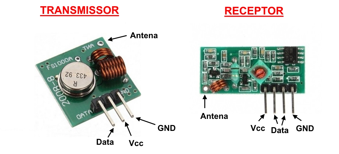
- RF Module (433 Mhz) - Transmitter and Receiver pair
Explain the programming process/es I used.
- Search for information about communication devices (see datasheets, configurations, connections, powering devices, etc.)
- Search for compatible libraries with microcontrollers (if any)
- Connection sketch design
- Development of the programming of the issuing device for each of the exercises carried out or according to any form of communication that is being experienced.
- For UART activity, connect the RX and TX communication PINs of the sending device cross-wise with the RX and TX communication PINs of the receiving device. We proceeded with sending a character as a message
- The commands used in this programming are the following:
- Serial.begin (9600); // Using a 9600bdrate communication)
- Serial.println (): // Used to send data through the serial port
- The following commands were used for the receiving device:
- Serial.available (); // Validate if there is incoming information on the receiving device
- Serial.read (); // Insight into the data that reaches the device
- Serial.println (); // Writing of the data that has been received
- For the development of the second example it is important to carry out the first four points mentioned here:
- To program the devices with RFmodules is not necessary to use any library, but if you want to, this one could be usefull Manchester.h
- The program starts describing the variables that I going to use
- Next, defining the output, using a "For structure" lets specify the data to transmit white a LED opened.
- Finally, configuring the Low transmitting signal.
For this activity, I want to do two communication exercises using Serial and also by radiofrequency modules, this last activity because I am interested in knowing how to link this series of devices to Agrotechnology projects, where communications by physical buildings and wireless coverage does not exist from Internet.
UART COMMUNICATION
As an important fact, I will use the experimental plates that I designed in the previous activities, this to affirm the didactic use of my designs and to encourage people to use other alternatives to the Arduino boards. So in this activity Im going to use two boards of my design, for this reason I have fabricated a copy of my experimental board. The design is the following:
.The connectivity diagram is as follows
This interconnectivity is the simplest and allows to establish communication efficiently with many other devices, softwares, systems, etc.
If you want to program the Attiny44 microcontroller using the Arduino IDE, I share some information that I have collected that can be useful when you will program the microcontrollers and use SerialPorts.
The most important functions that we must know to handle the serial port are: begin (), read (), write (), print () and available ()
Begin ().- Stable the baud rate of the UART for the serial transmission, it is also possible to configure the number of data bits, parity and stop bits, by default it is 8 bits of data, without parity and a bit of stop https://www.arduino.cc/en/Serial/Begin.
Read ().- Reads the first incoming byte of the serial buffer. https://www.arduino.cc/en/Serial/Read.
Write ().- Write data in binary about the serial port. The data is sent as a byte or series of bytes.
Print ().- Prints data to the serial port as ASCII text, also allows printing in other formats. https://www.arduino.cc/en/Serial/Print.
Available ().- Gives the number of bytes (characters) available to read in the serial port, they are data that have arrived and are stored in the serial buffer that has a size of 64 bytes. https://www.arduino.cc/en/Serial/Available.
End ().- Disables serial communication allowing the RX and TX pins to be used as digital pins. https://www.arduino.cc/en/Serial/End.
If (Serial).- Specifies whether the serial port is ready. https://www.arduino.cc/en/Serial/IfSerial.
Find ().- Reads data from the serial buffer until the searched string is found. https://www.arduino.cc/en/Serial/Find.
ParseInt ().- Looks for the next valid integer in the data stream of the serial port. https://www.arduino.cc/en/Serial/ParseInt.
ReadBytes() .- Reads data from the serial buffer and stores it in a buffer variable. https://www.arduino.cc/en/Serial/ReadBytes.
SetTimeout () .- Sets the maximum number of milliseconds to wait for the serial port to read. By default it is a second. https://www.arduino.cc/en/Serial/SetTimeout.
readBytesUntil ().- Reads characters from the serial buffer and stores them in an array of characters, the function ends if the terminated character is found or the determined length has been read or reached the timeout. https://www.arduino.cc/en/Serial/ReadBytesUntil.
SerialEvent ().- Called when there is data available. https://www.arduino.cc/en/Reference/SerialEvent.
flush ().- Waits until the complete transmission of the outgoing data. https://www.arduino.cc/en/Serial/Flush.
peek ().- Returns the next character in the serial buffer but without deleting it from it. https://www.arduino.cc/en/Serial/Peek.
ReadString ().- Reads characters from the serial buffer and stores them in a string. The function ends when a timeout occurs. https://www.arduino.cc/en/Serial/ReadString.
The programming for each plate is detailed below
DEVICE 1
Implement and interpret programming protocols
DEVICE 2
Implement and interpret programming protocols
DEMONSTRATING
EXCERSISE 2
In exercise number two I will practice using the radio frequency communication devices, ideal devices to be applied in places where there is no internet coverage, telephone or any other type of communication.
To start with this exersise I recommend to check this tutorial.
The elements that Im going to use are the following:
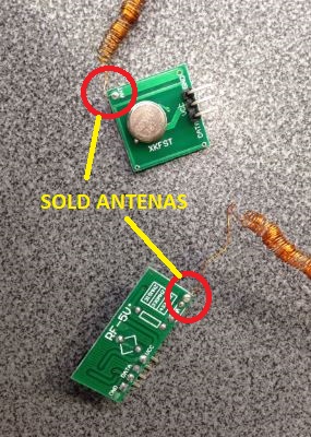
To start wth this activity I recomend to sold the antenas on the device PIN for antenas to improve their communication.

To know more about the device, I share their datasheet here

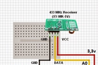
CONECTIVITY
EMISOR

RECEIVER
The program consists of the following: the emitting device will send a signal accompanied by a blink of LED (blue) by radiofrequency at 433MHz and the receiving device will be in charge of receiving the signal and replicating it in the receiver circuit, using its LED (network). The emitting device uses a power supply of five volts, and our FTDI power cable provides only 3.3v so it is important that a device is used as an external source to power this device.
The programming for the two plates is the following:
EMISOR
RECEIVER
Here I share a video aplying the programming on devices
The programming process for each of the exercises that have been carried out were the following:
Outline problems and how I fixed them
There are some elements or electronic devices that work at variable voltages, which can complicate the use of a single source of voltage that provides a single type of signal, it is also important to know that the power supplies through a USB port connected from a computer , does not provide an adequate current that the circuit could need, which is why it is important to use external power supplies that supply the voltage or current required, in the case of radio frequency sensor activity, they have been taken from an Arduino board.
Here I share a video with a demonstration of using external source.