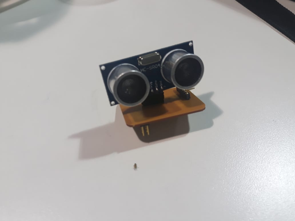
For this weekly activity, I am going to design an electronic distance alarm plate that involves as input the data of an ultrasound sensor coupled to an Attiny 45 AVR Microcontroller.
Next I will start with the development of the electronic board using the skills in design of electronic boards obtained weeks ago, for this activity it is important to get the following elements:
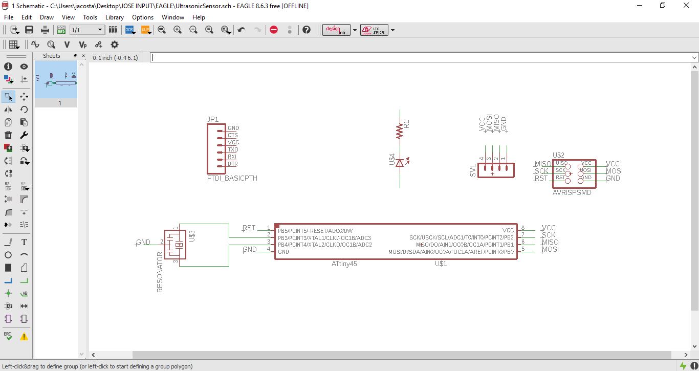
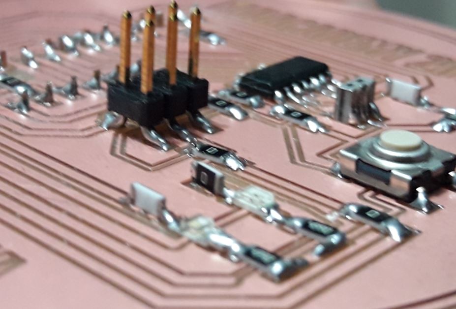
We will start doing the design on Eagle software, to do this, I will create a scketch and then I'll proceed to integrate the different devices beforehand and make the respective connections.
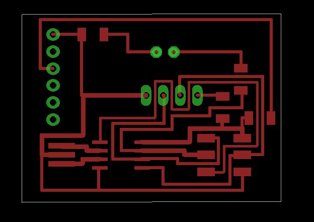
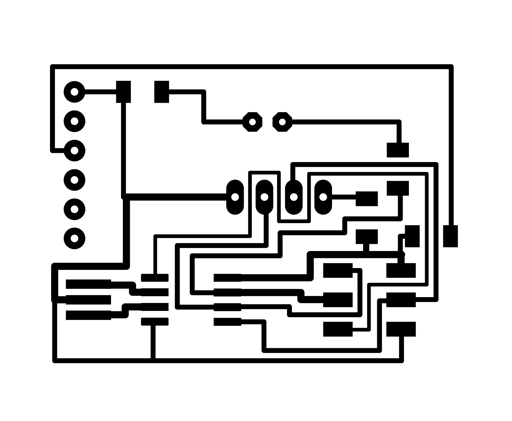
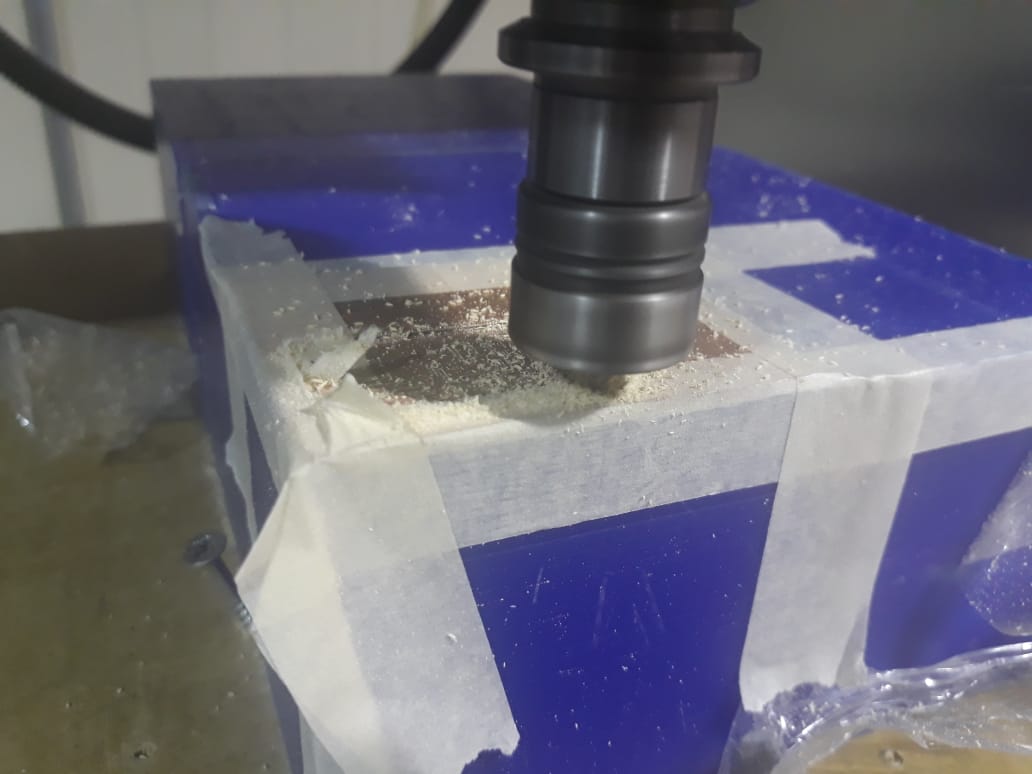
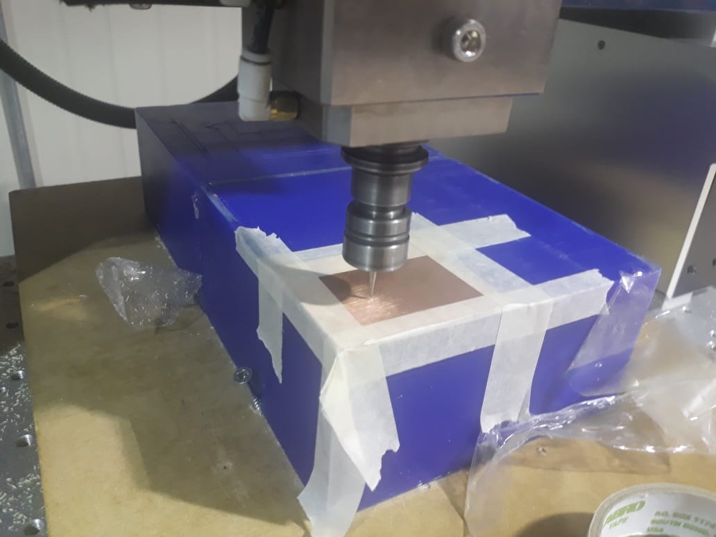
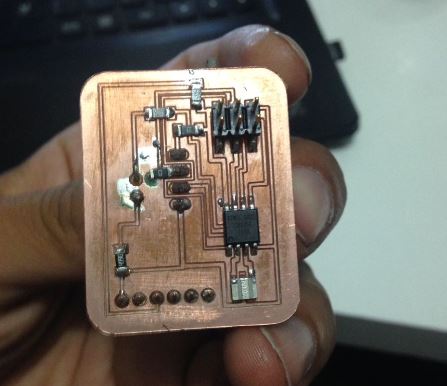
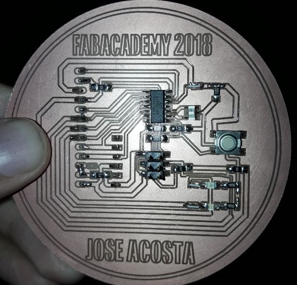
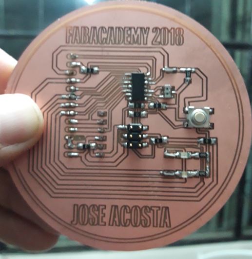
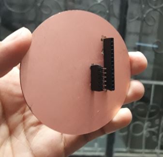
Once created the design we go to fabmodules to create the G code of the electronic design, later it is manufactured in the CNC of engraving of electronic plates as it was learned in previous activities.
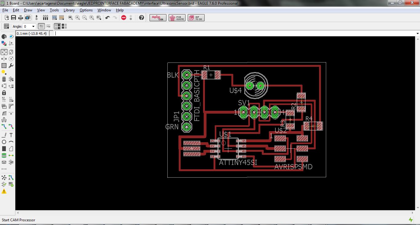
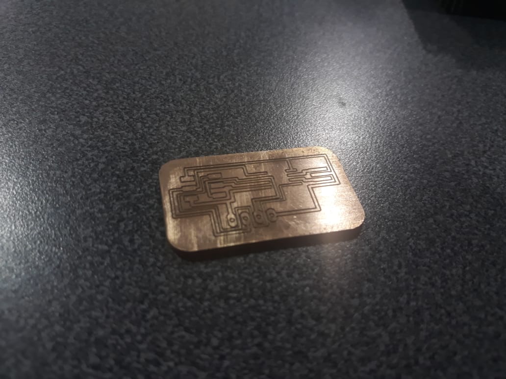
Then we created the design of the electronic board in a virtual way according to what we learned weeks ago, in the option of creating PCB in the Eagle design software, we designed the most appropriate way to locate the elements and make the tracks.

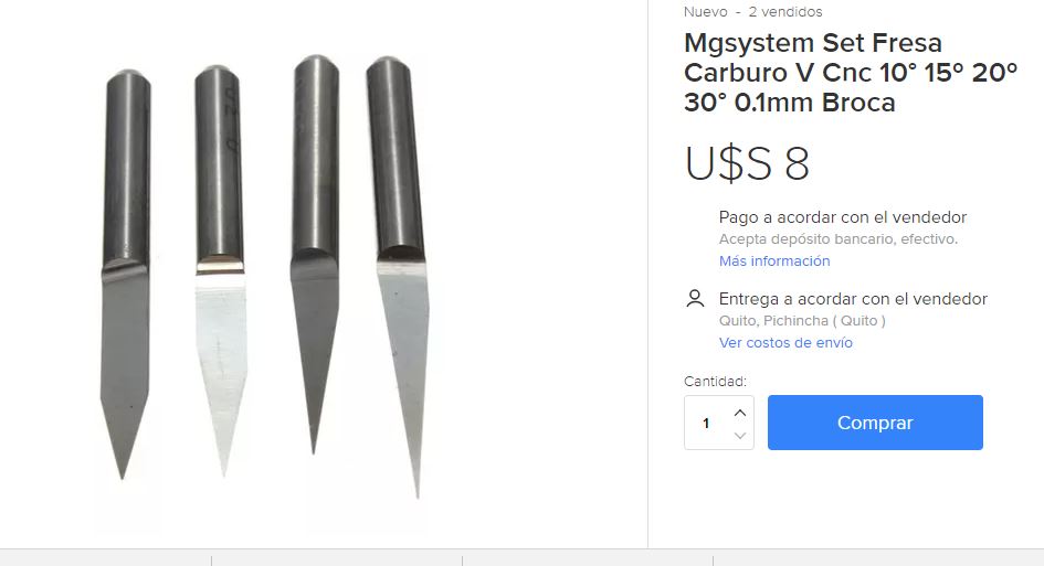
For the activity I selected the tip below, it has a 0,1mm diameter and a wall inclinated with and angle of 10 grades
In addition, the parameters for routing the path and the cutting pattern of the electronic plate shared in the group practice of week 5 will be used.
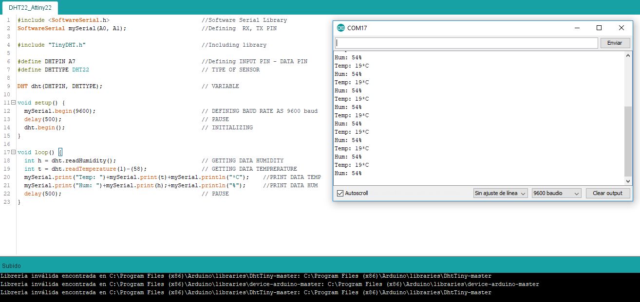
PROGRAMMING
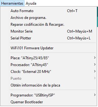
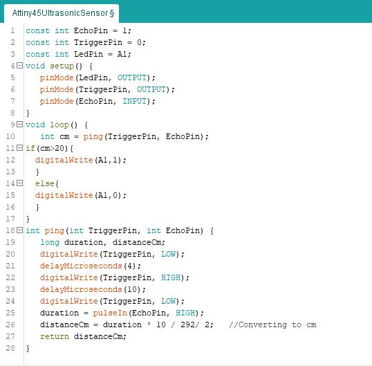
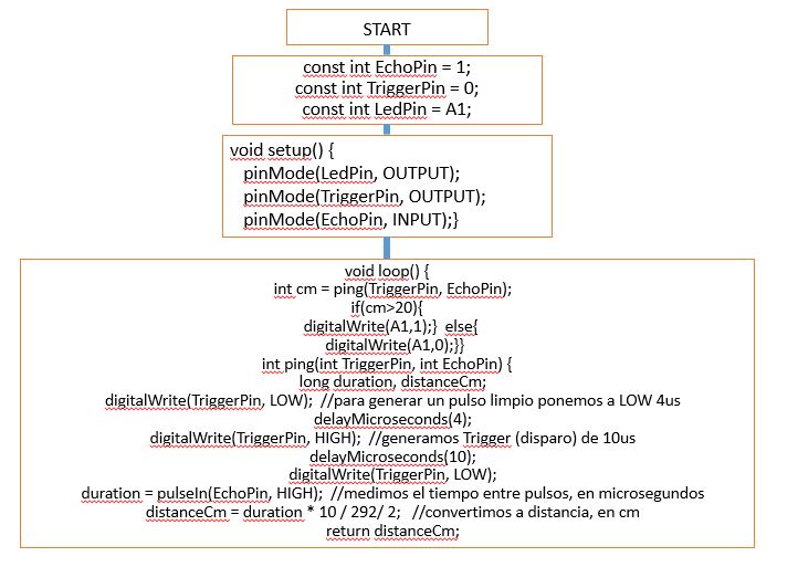
Next the programming of the microcontroller is presented, for this we use the environment of arduino, next I share the programming of the electronic board. It must be remembered that within the configuration of the tools it is important to select the microcontroller to be used, the frequency of the resonator and the type of burner to be used.
Implement and interpret programming protocols
EXCERSISE 2
As an extra activity, I have developed some exercises to test some sensors on the board that I have manufactured previously and in this way validate its functionality as a board for experimentation such as Arduino.


Once the design is done it is opened in illustrator to apply custom designs and images according to the options that the software allows. Once saved will be created two designs, one that corresponds to the engraving of the plate and another to the contour to be machined in the precision milling CNC, we will use FabModules for the conversion of the designs in G-Code, and open it with the machine, it is It is recommended that the engraving surface be totally and strictly flat to avoid problems in engraving and contour cutting
HUMIDITY - TEMPERATURE SENSOR DHT 22
DHT11 and the DHT22 are two models of the same family of sensors, which allow the simultaneous measurement of temperature and humidity.
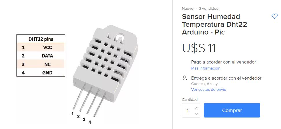
These sensors have an internal processor that performs the measurement process, providing measurement through a digital signal, so it is very easy to obtain the measurement from a microprocessor.
Both sensors have a similar plastic encapsulation. We can distinguish both models by the color of it. The DHT11 has a blue housing, while in the case of the DHT22 sensor the exterior is white.
Of both models, the DHT11 is the little brother of the family, and has worse technical characteristics. The DHT22 is the superior model but, on the other hand, it has a higher price.
DHT22 model has the following characteristics.
The DHT22 (without being at all a high precision sensor) has acceptable characteristics so that it can be used in real monitoring or recording projects, which require medium precision.
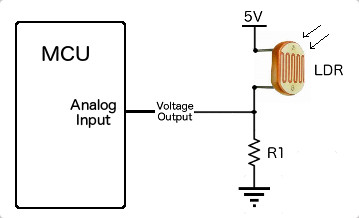
PHOTORESISTOR
Photoresistivity is an electronic component widely used and seen in the field of optoelectronics, this small component has a variable internal resistance which increases or decreases depending on the light that is affecting it.
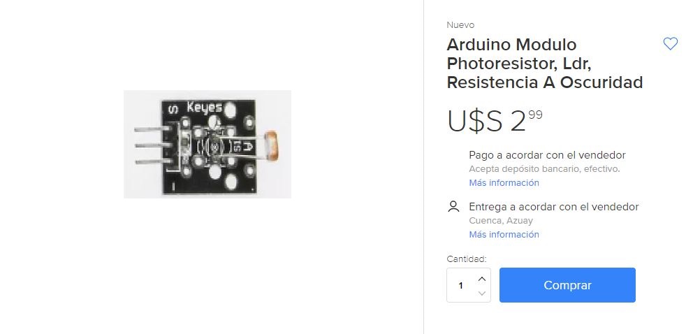
The resistance of a photoresistor decreases if there is an increase in light intensity, otherwise the intensity of light decreases the resistance increases. This component is also known as: Photoconductor, photoelectric cell or light-dependent resistor.
The acronyms LDR are used to name the conventional photoresistors, these acronyms mean: light-dependent resistor (Light-dependent resistor)
Next, I will present the program to control the operation of photoresistance, it is very important to know the program structure
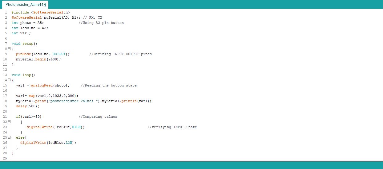
Then we will verify the demonstration of the operation of a photoresistor from our pre-programmed plate, if the passage of light to the photocell will be interrupted by a dark obstacle, and the LED that integrates the plate will proceed to change state. I will leave the demonstration video for more demonstration of the activity
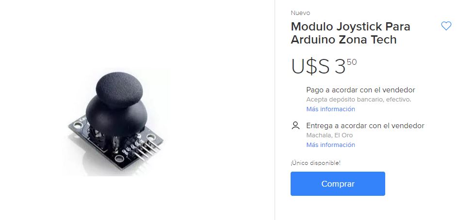
JOYSTICK
The Joystick module has 5 pins: Vcc, GND, VRX, VRYY and SW. Keep in mind that the labels of other models may be slightly different, depending on where you purchased the module. The joystick is analog and should provide more accurate readings than the simple directional levers. In addition, you can press the joystick down to activate a button.
We have to use analogue Arduino pins to read the data from the X / Y pins, and a digital pin to read the SW button. The SW pin is grounded, when the joystick is pushed down. To get stable readings you need to be connected to Vcc through a pull-up resistor.
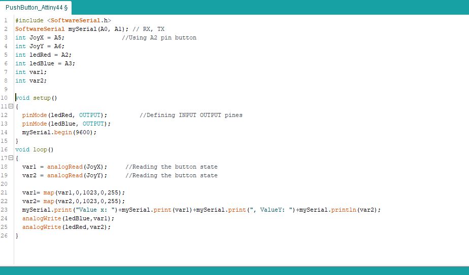
For this activity the joystick module was used, which consists of two analog inputs and a digital one, to obtain the data it is necessary to create two variables to store the analog variables and then compare them with a predetermined value so that the ignition LEDs are activated. Next we can visualize the programming of the plate
Now, I will share a video linking my board with the joystick
For each of the activities carried out it was important to review the operating datasheet of each device to be used, because they have their different configuration. According to the inputs selected for this activity, we have the following datasheets:
GROUP ACTIVITY
As part of the development of the group activity of this activity, we have made the respective measurements with the use of the multimeter, also the visualization of the signal with the oscilloscope.
MULTIMETER TEST
OSCILOSCOPE TEST
To link some types of sensors to the microcontroller you need programming libraries, so it is recommended to download the libraries and perform the respective tests.
In the development of this week's activities there were no problems of design, machining and performance tests.
ATTINY45_ULTRASONIC download
ATTINY DHT22 download
ATTINY PHOTORESISTOR download
ATTINY JOYSTICK download