The output captabilities of microcontrollers allow us to control digitaly or pseudo-analogically a wide range of devices. In this assigment, we are going to explore this features.
assignment
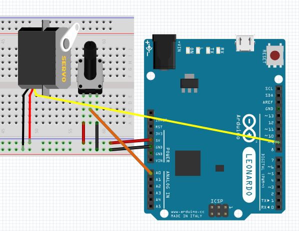
For hardware/software I started using an arduino Leonardo. It uses the same chip we are going to use for the board personal design and fabrication. Using and arduino for prototiping might be good, in case we want to change the design or the program, we can do it using this prototiping board, and when we are done with the testing, we continue to the board design and fabrication. The code then will need very few changes before implementation. This complies with the comercial board policy, and will be used only for testing and sofware development. Here is an setup for a potentiomenter and a servo.
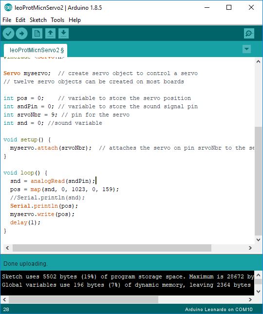
Here is an example of the code. Inside the document, there are also notes writen as comments through the code.
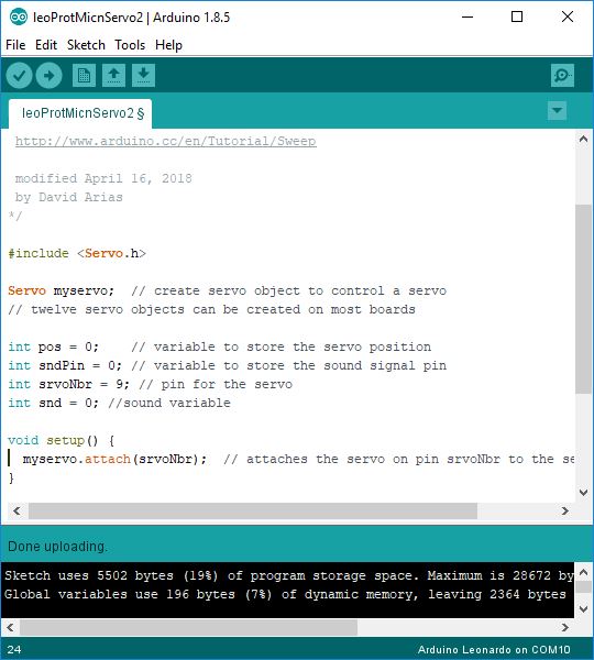
For the servo, we need to include the "servo" library.
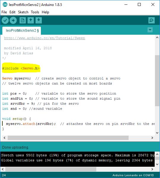
Then we create a servo object myservo, declare some integers to store information, attach the servo in the setup function, and read, map, print, and order the servo to move. I tested a delay of 1 milisecond, but some larger number is recomended.
This is the preliminary software design. We are going to move it to a lab-made board when it's ready.
Update:
There was a change in the motor used based on the necesities for the final project. The servo motor was changed for a stepper because of the limitation of servo turn and precise control, aimed to the final project development. The arduino was also changed, due to the new board already machined and working.
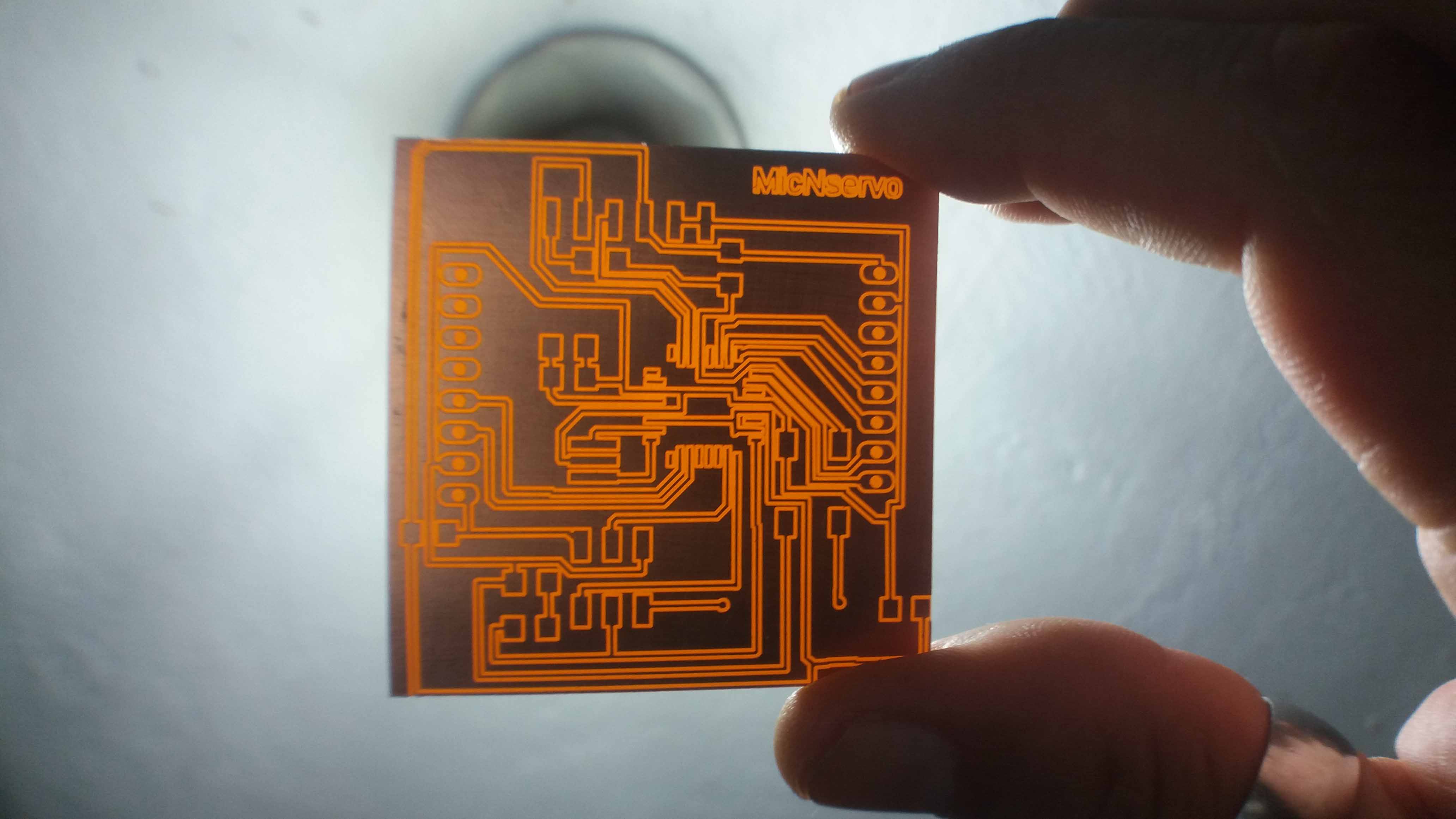
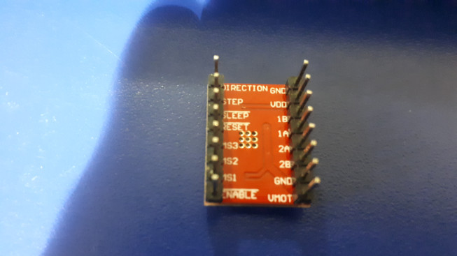
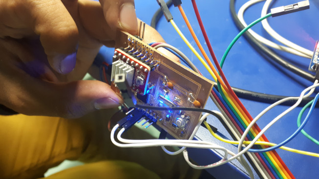
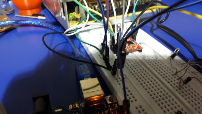
The pseudo-arduino board for the final project was finally ready. The core is a atmega328A, with a 16Mhz crystal, input pins enabled and a stepper motor controller attached. I am using this device to control a stepper motor foccused also in the Final Project implementation. Here we can see the board and the controller. The controller device is the Pololu A4988 driver.
We can actually drive the stepper motor with the board alone, but using a dedicated driver save us from using pins. Also, a dedicated device is designed for just one thing, optimizing performance.
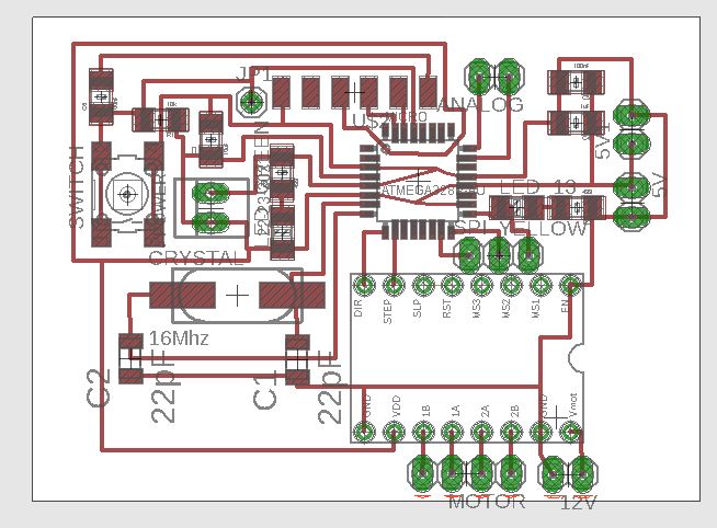
The board was a modification of the Satscha kit, with an space available to accomodate the Pololu A4988 driver. The design is shown in the next picture.
This is the controller for the stepper.
This is the board with the space dedicated for the stepper controller.
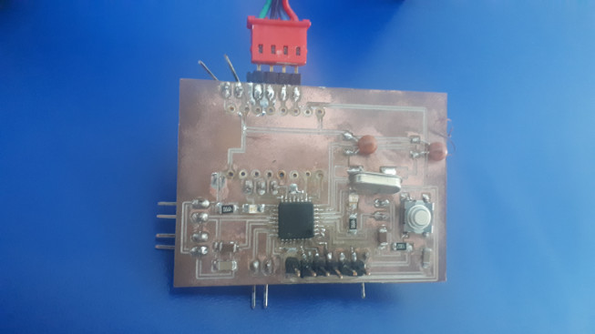
Here, the driver and the board attached are shown.
The schematics for this board can be found here. In the following link, the board is available.
Code explained:
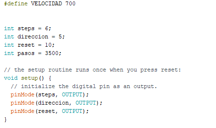
First, we define the velocity (VELOCIDAD) as 700 (ms). This will be used later. Then, we declare the pins for the steps, direction, reset, and steps (pasos). Then, in the setup funcion, we define them as outputs.
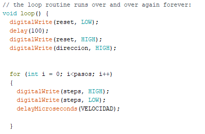
In the loop function, we set a digital write LOW for the reset. This turns the motor off, saving energy and reducing the stress on the device. After a delay of 100 miliseconds, we set it HIGH, ready to receive instructions. Then, we set the direction HIGH, to indicate a clockwise direction. Then, we set a for loop with increments of 1 (i++) and the variable "pasos" as the number of steps. The velocity stated previously dictates de speed of the motor.
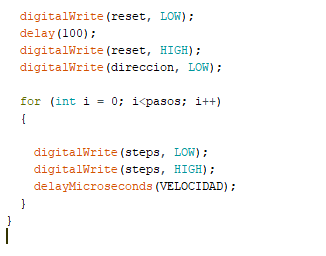
Finally, we repeat the code, but this time we set the direction as LOW, changing the direction of rotation (counterclockwise).
The pins are connected to the boards pins as described in the following lines:
Direction:
This pin defines the direction of the motor's rotation. It is conected to a pin in the fabbed board (except the communications pins).
GND:
Ground. This pin is a goes to a common ground together with the 12V power supply GND.
Step:
This pin sets the steps the motor will make. It goes to any pin in the fabbed board (except the comminications pins)
VDD:
This pin is connected to the + voltage of the fabbed board.
Sleep:
This pin could control if the motor is on or off. In our case, we are going to set it always on, so it will be connected to the reset pin of the stepper-controller.
Reset:
As we said before, this pin is connected to the Sleep pin.
MS1, MS2 and MS3:
This pins set the resolution of the motor in microsteps. We are not going to connect them in this exercise.
Enable:
Turns the motor on (or off). It will not be used.
VMOT and GND:
This are going to provide power to the motor. They go to a source of voltage higher then the chip, usually bewteen 8V and 32V. Be carefull not to fry your board! The ground is common with the fabbed board and the stepper controller board.
1A, 1B, 2A, 2B:
This pins provide power to the reels of the stepper-motor. I am going to use a motor with four connections. They are marked in the motor too.
Before connect everything, I tested the connections in a breadboard.
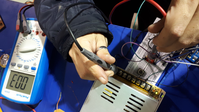
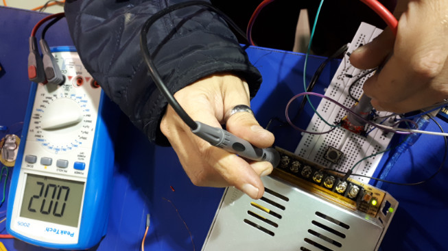
Voltage/current calibration
For calibration (setting the voltage/amperage of the specific motor), we measure calculate the refference voltage using the data from the motor, in Amps. For the calculation, we use the formula Current Limit = VRef x 2. Then, we regulate the voltage with the little screw that drives a potenciometer. This pin is also used as a refference pin.
Finally, we connect the motor and run the test code.
The following video shows the device in action.
Here are the files to download: Inicial program prototype, Second program prototype, fabKitModified (skematic), fabKitModified (board).
