In this class we are going to explore the comunication between chips/devices. I am going to explore serial comunication, but I'm also interested in technologies like I2C and wireless.
assignment
Make two or more boards comunicate
First part: Design.
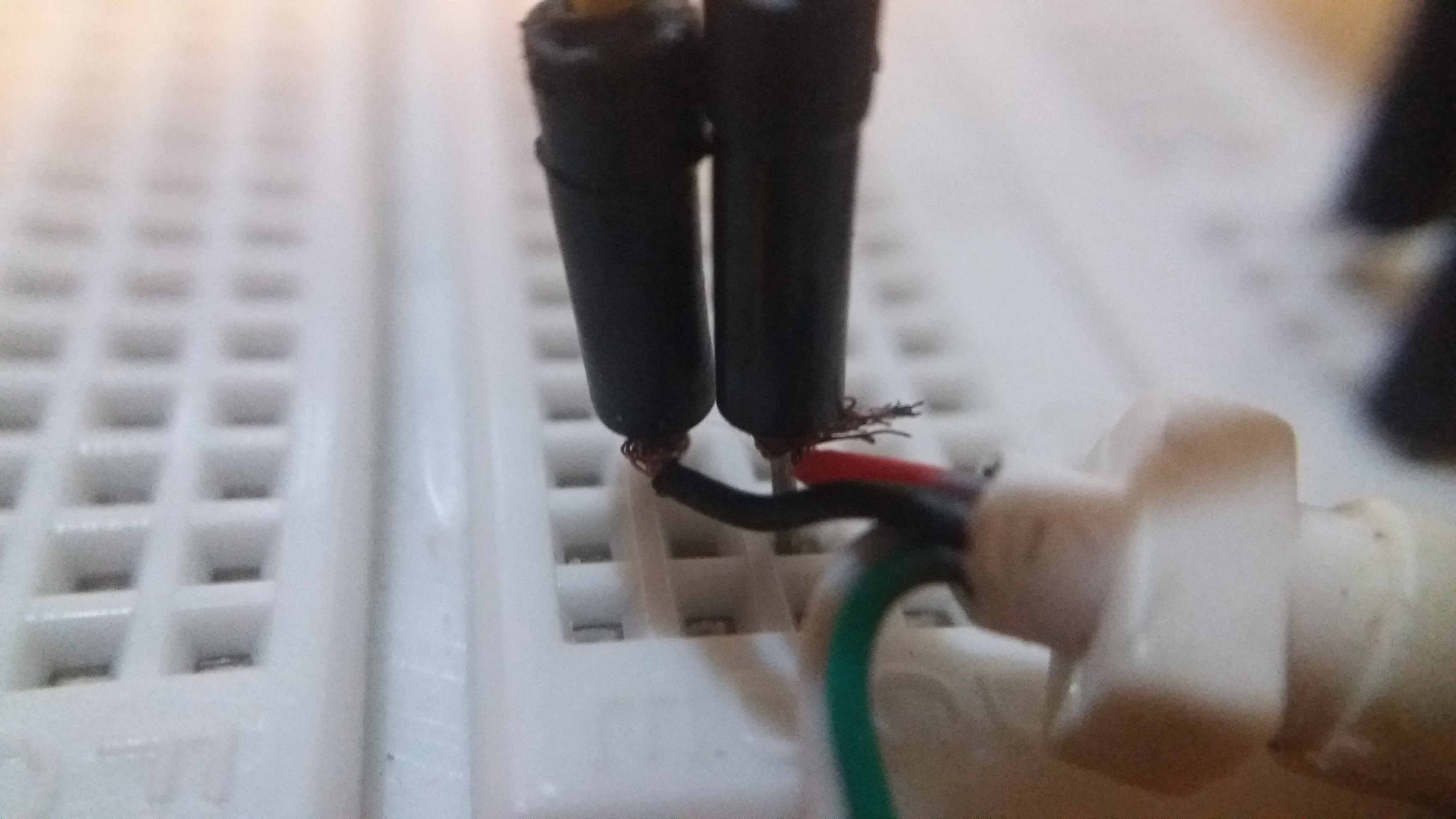
I had two breadboard type ATtiny44A chips around, and I wondered if I could use them for this task. So I started providing power to the board. 5V from a cut usb cable. They have four cables, two for power, two for communication. I'm going to use just the + and ground cables, red and black. I tested them with the multimeter, and they were oposite to the conventional red for +, black for ground. I guess sometimes they don't stick to the convention.
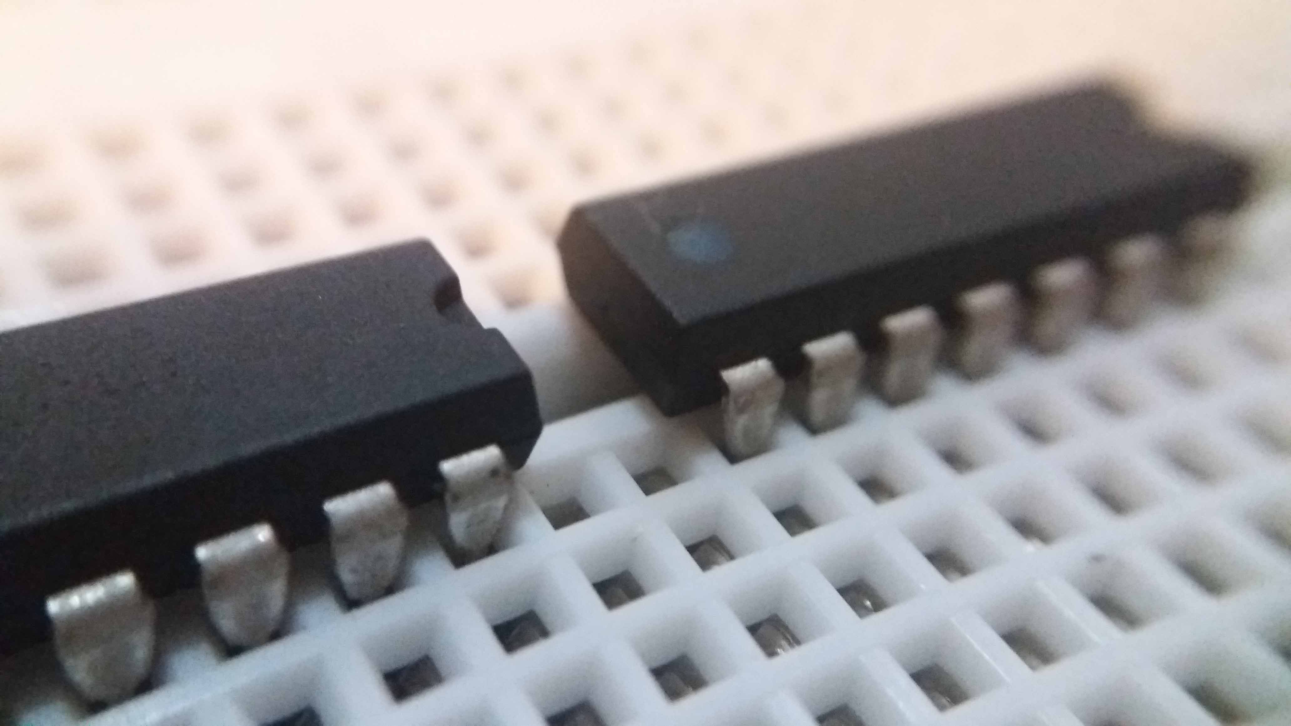
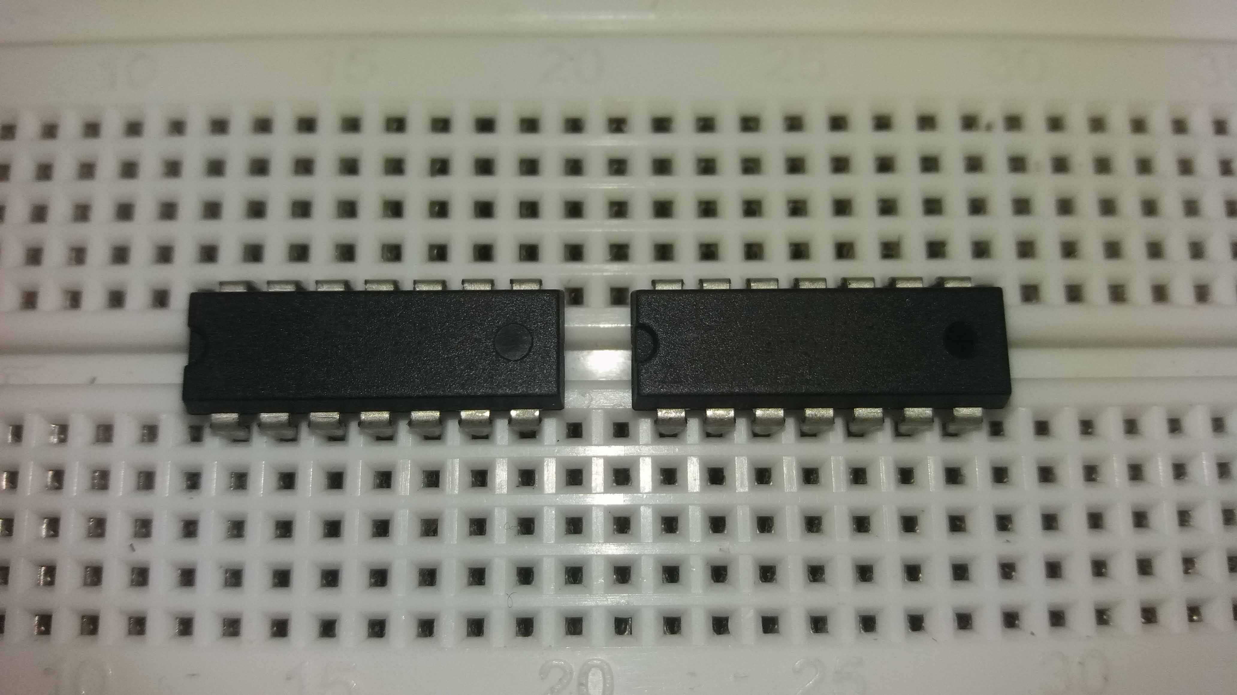
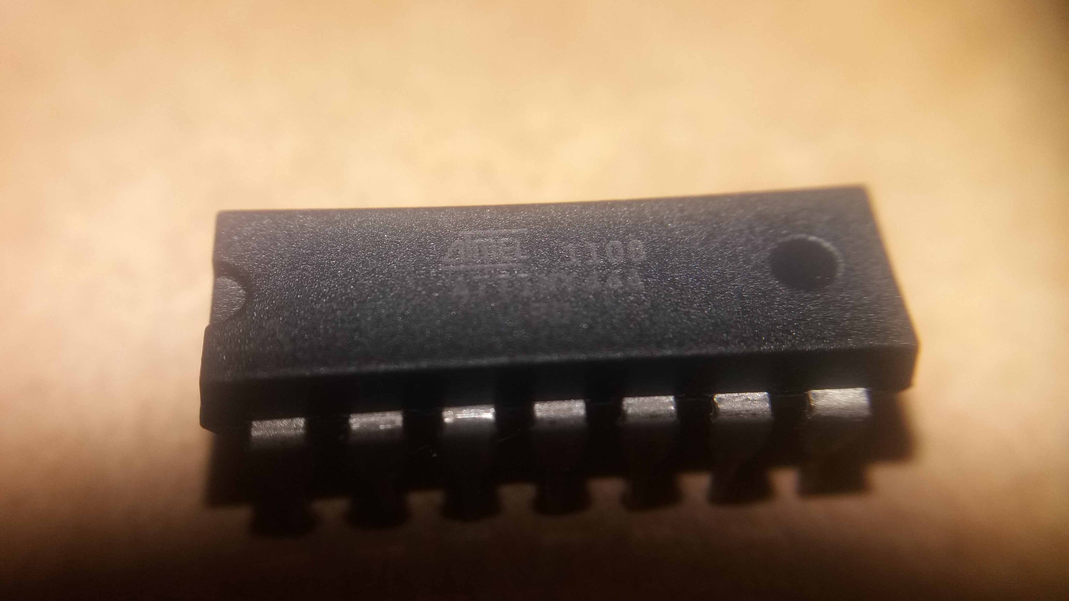
Here are the two chips. Identical ATtiny44.
Here a good descrition for the chip can be found. This is the link for the Datasheet. The pinout for the chip, is shown in the next image. The color code is very useful.
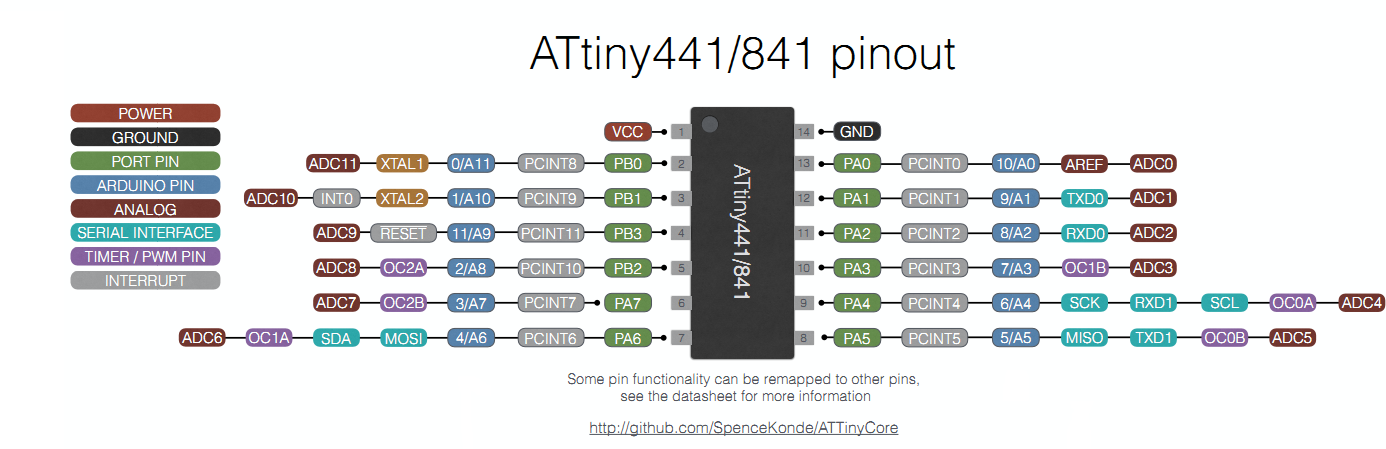
This information can be used to wire the chip to our programmer.
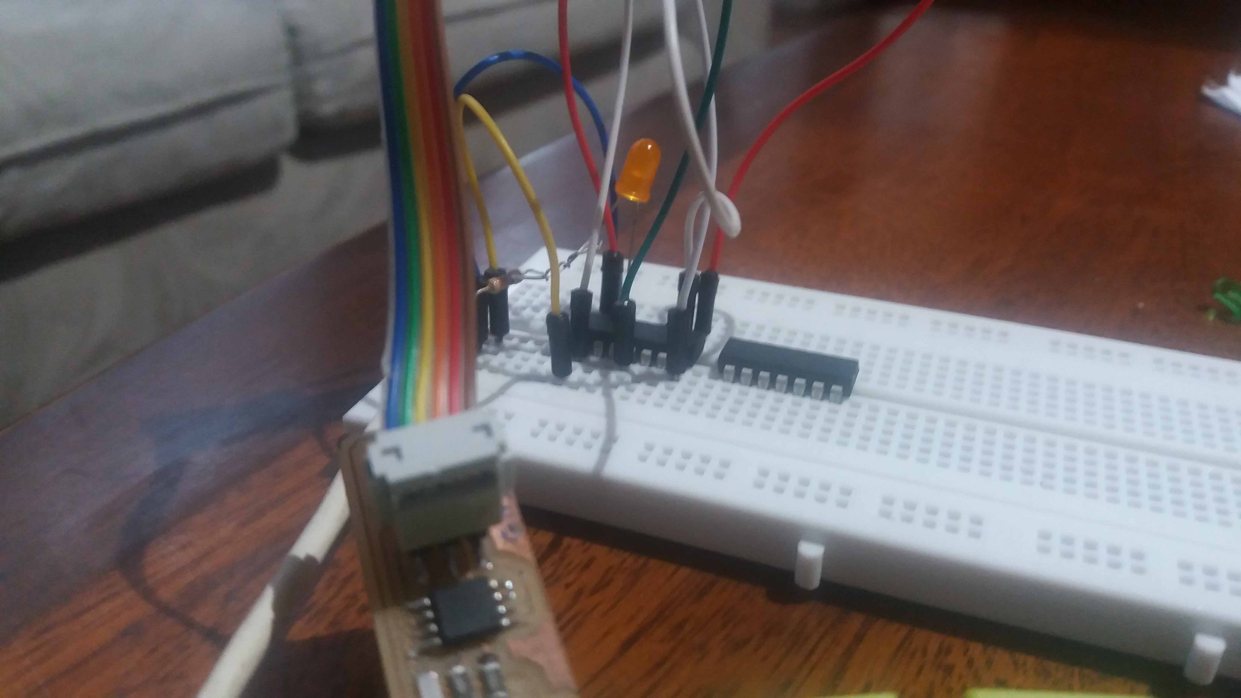
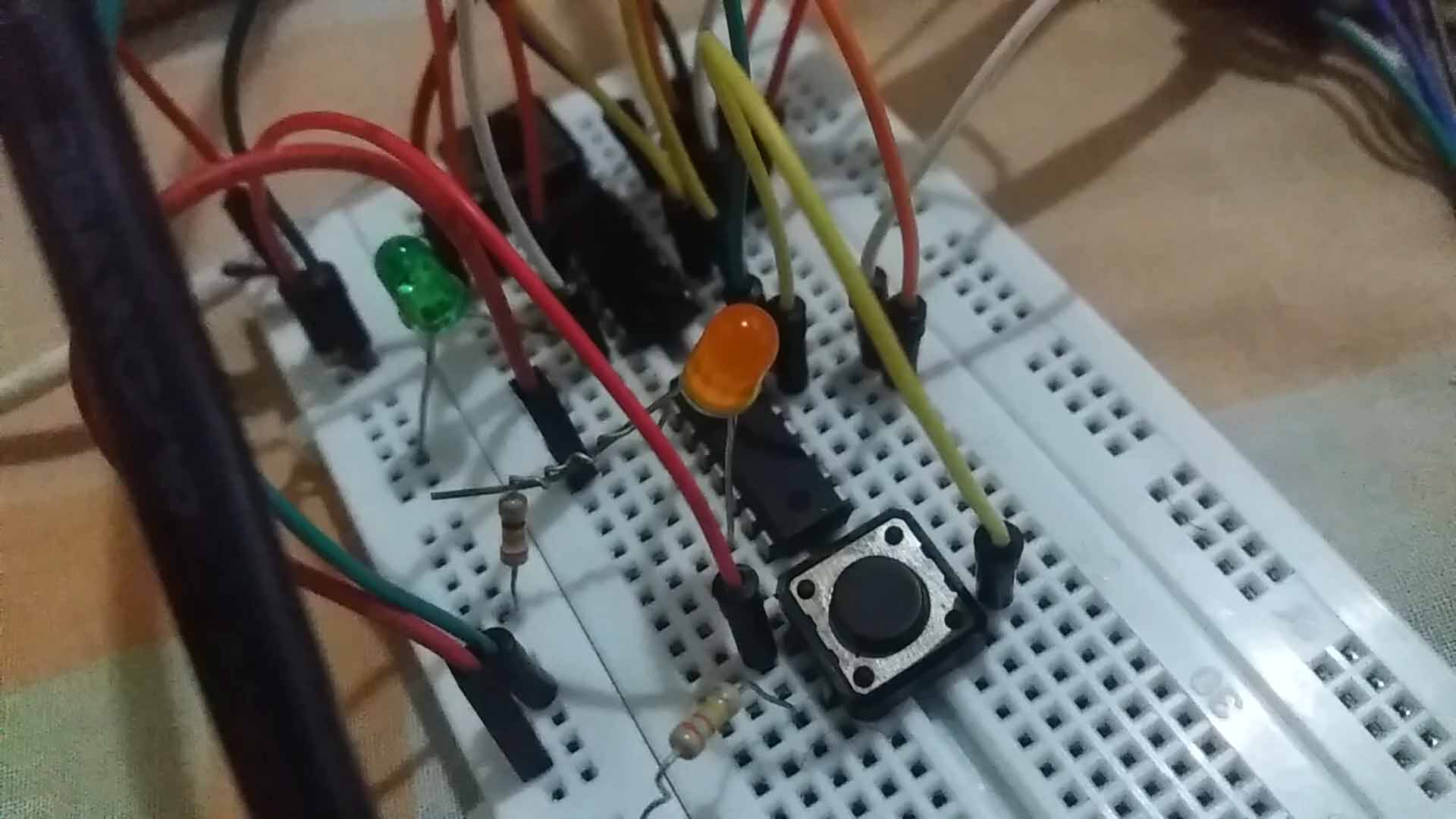
So I wired the chip according to the diagram. Ground to ground, Vcc to vcc, and so on for the six programming cables. I added power to the chip and a LED with with it's resistor to the pin 6 of the chip (pin 7, in the code for the Arduino correspondance). So I burned a bootloader with the internal clock set at 8Mhz, and then, to test it, I uploaded the clasic "blink" program. At action, the led is on for a second (1000 miliseconds, to be exact), then turns off for another thousend miliseconds, and loops forever. On for a second...
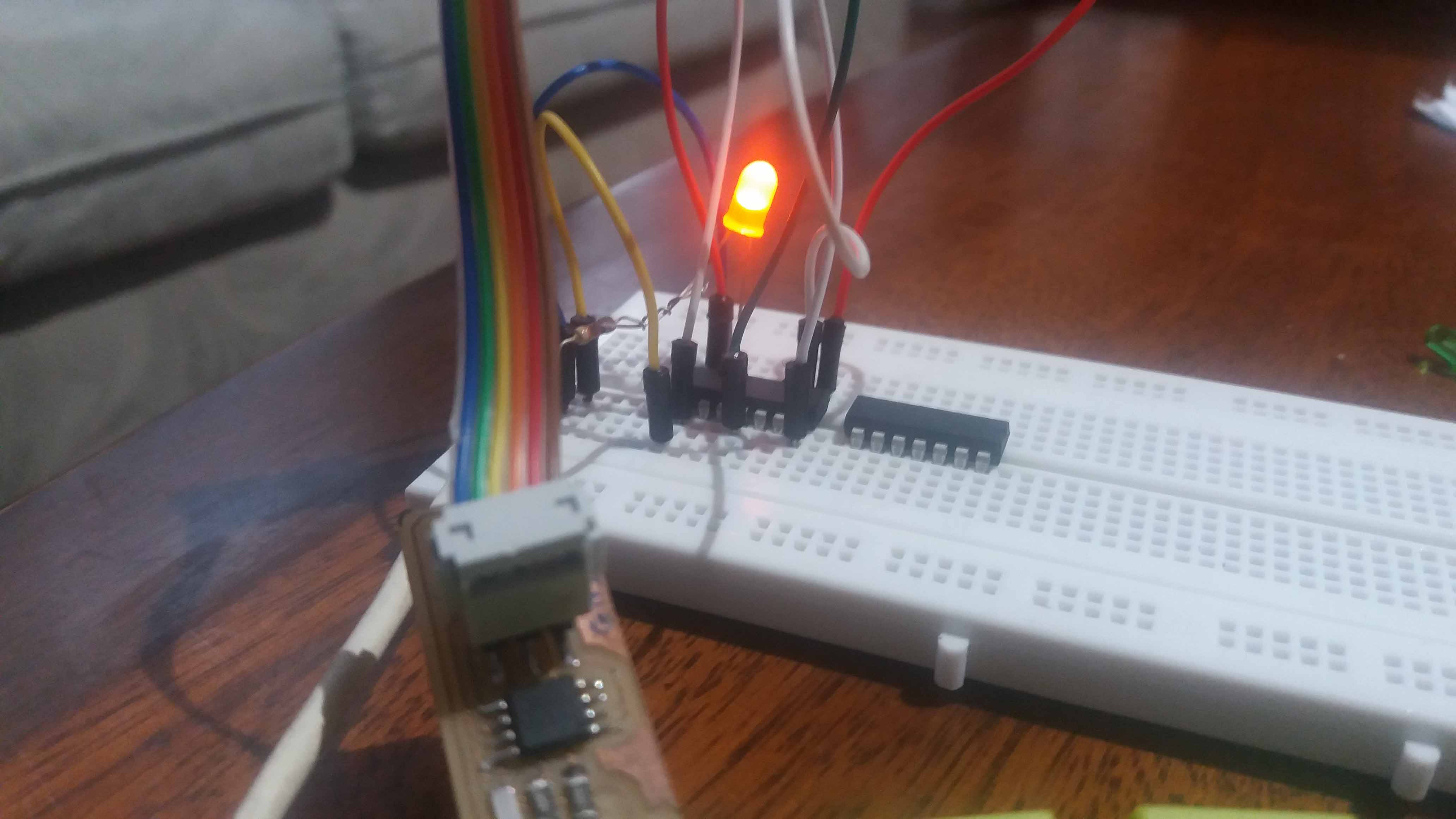
...and off for a second.
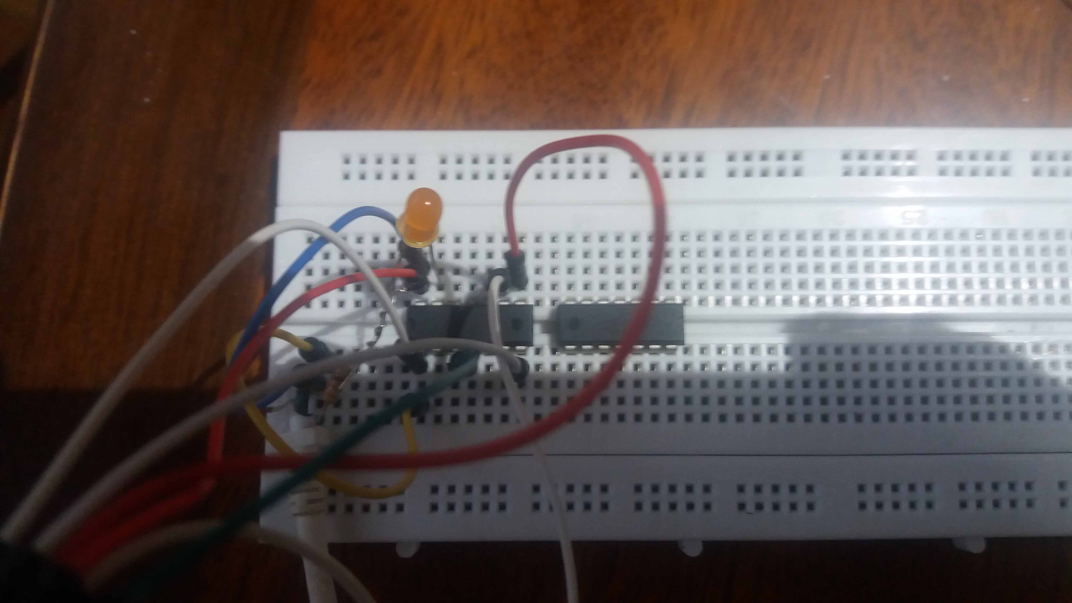
Having this wiring is practical. It is easy to change only the chip, provided they are the same model, and program the second chip easily.
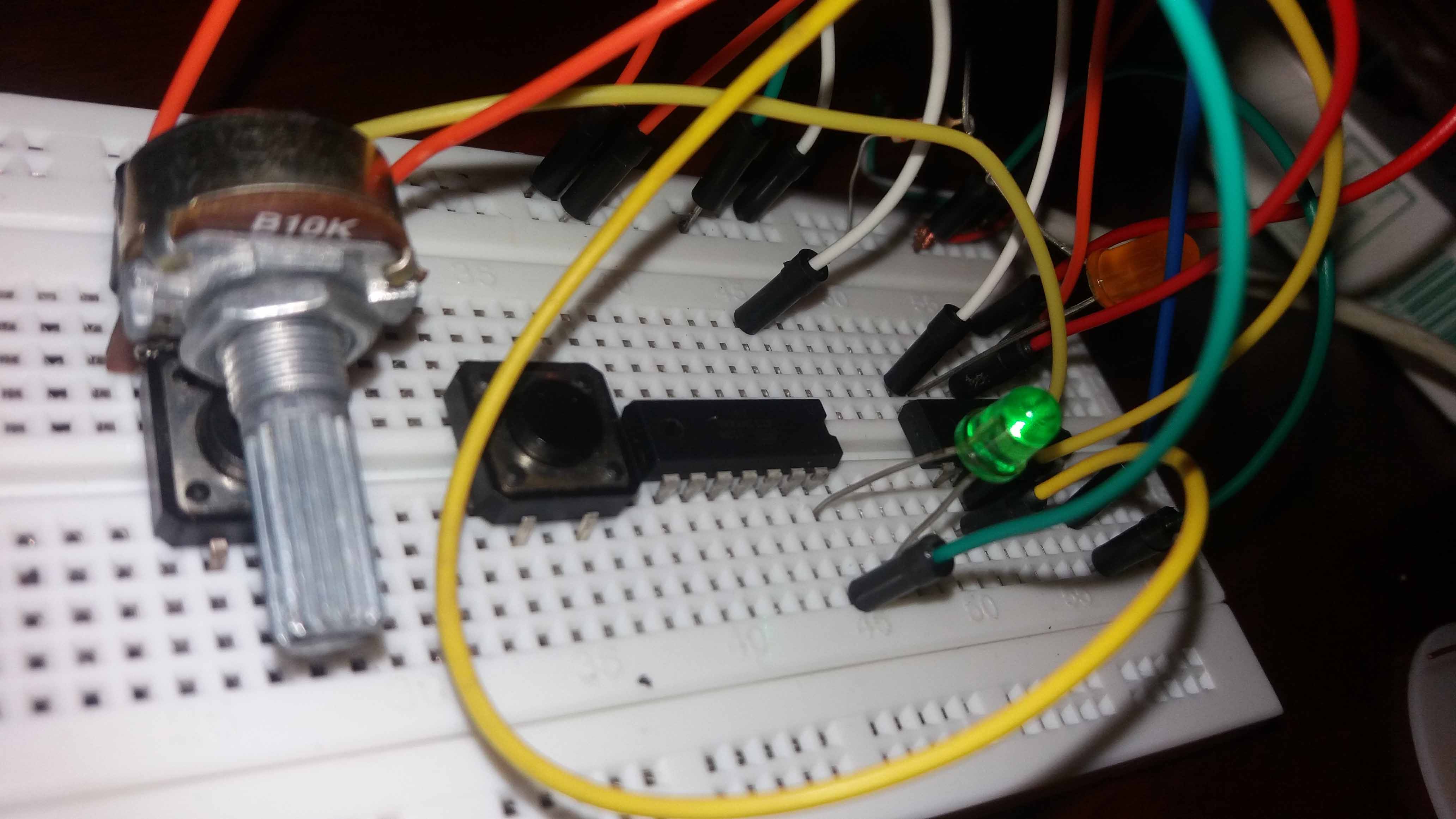
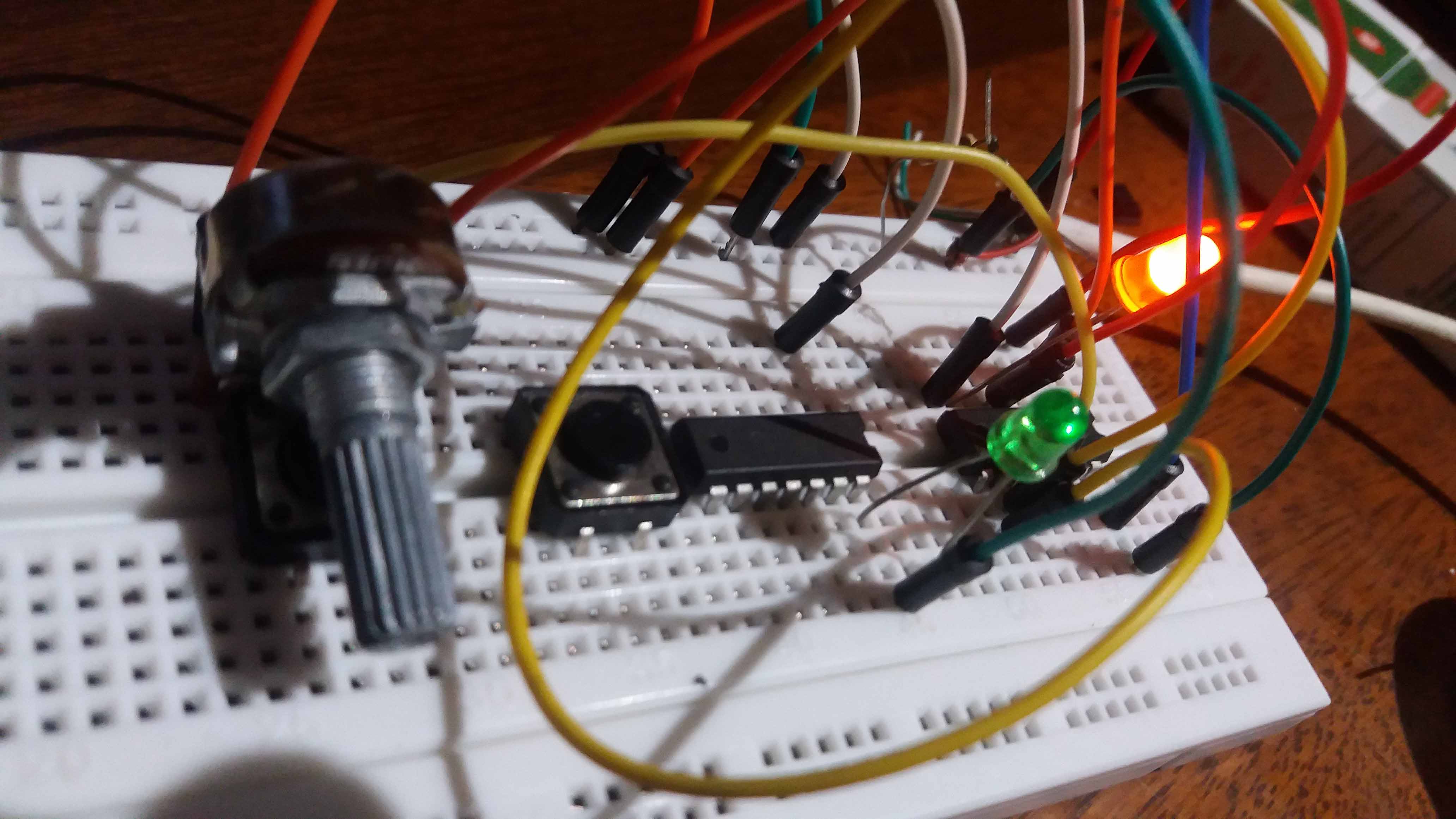
I added a potenciometer (variable resistor) to test the PWM caplatabilites of the chip. It worked fine modulating the intesity of the orange LED according to the position of the knob of the potentiometer.
The code for this project can be found here: LED_POT_ATTINY44.
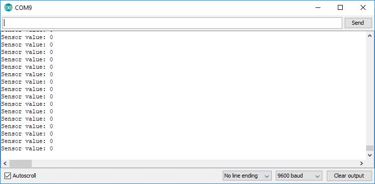
If we connect the TX wire of a FTDI conector to the RX pin, and a RX wire to the TX pin, we can have the data red by the chip on the potenciometer input. We have to remember that, for this kind of chip we have to use SofwareSerial library, to emulate the hardware serial other, more powerful chips, have. But nevertheless, it worked like charm. With the pot completely turn to one side, we read in the Serial Monitor a value of 0:
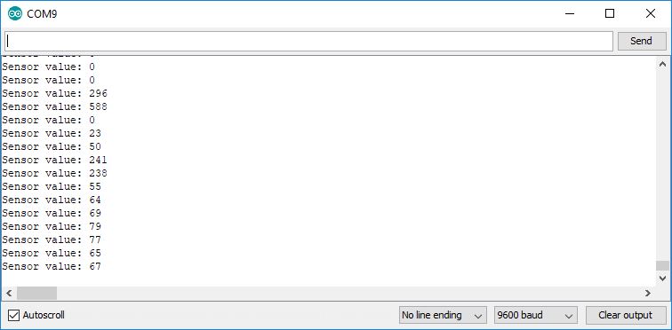
And when we turn the pot to the other side completely, a value of 1023 is red:
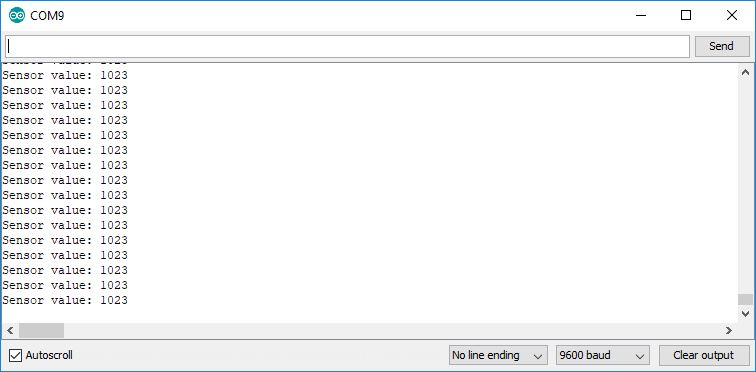
What makes sense, since the analogRead() funtion transforms the analog signal (in this case the diference of voltages in the potentiomenter), to a digital one, from 0 to 1023 because of the ten bit analog to digital converter included in the chip. Two to the tenth equals 1023. We then just play with the pot to get intermediate numbers.
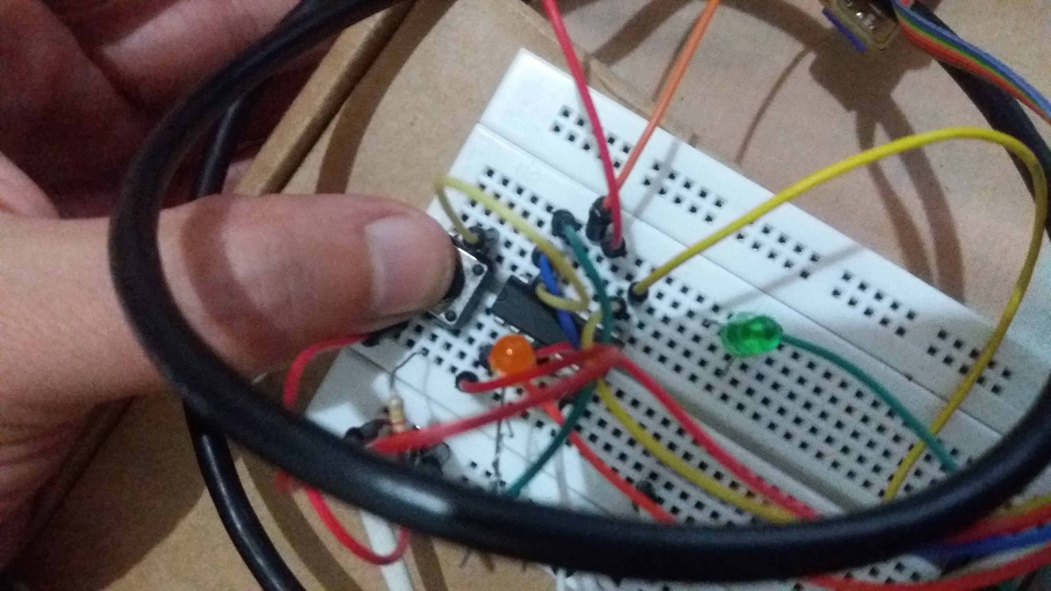
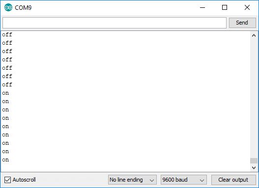
Then, I unpluged the potentiometer and hocked up a button. The intend is to have a digital switch for the LED that will show us if the board is recieving the button signal. It does. Here we see the states of the button unpressed and pressed. The code is here: LED_BUTTON_ATTINY44.
Unpressed:
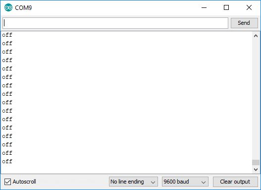
Serial monitor lecture:
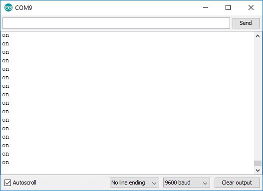
And pressed:
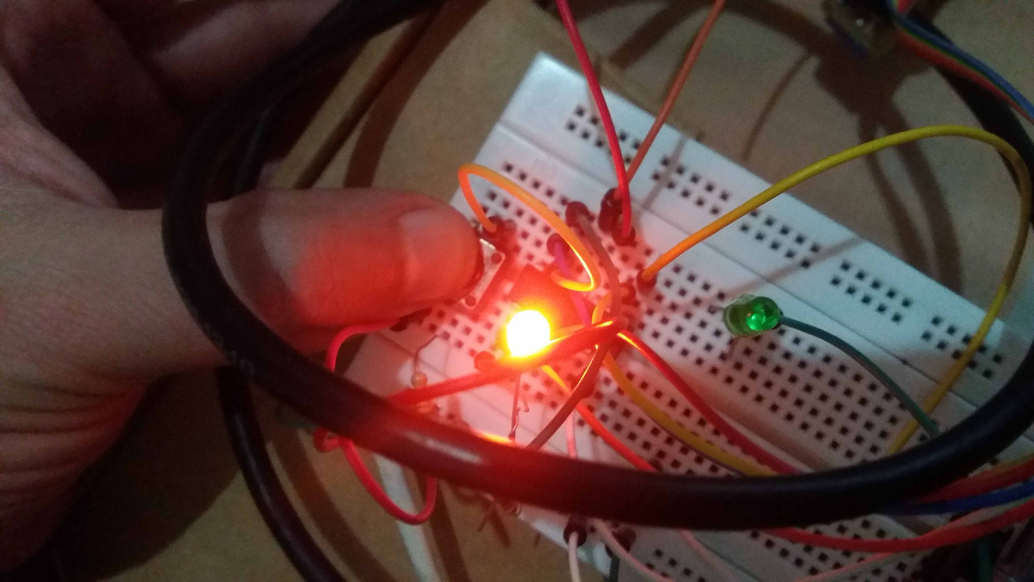
Serial monitor reflects the change.
With the button continuously pressed, the lecture stabilizes.
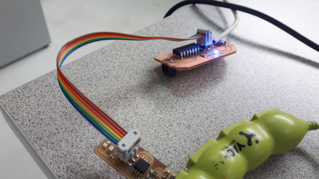
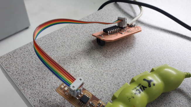
Finally, we use the programmer to download the code to the chips, one for transmiting, one for receiving. Here is the code for the receving chip: Receiving chip RX, and the transmiting one: Transmiting chip TX
According to the programm, once the button is pressed the orange LED turn on digitally and transmits the number 100 to the chip with the green light. The Serial monitor is reading the second chip (green). Notice that the 100 apears (almost) instantly in the monitor of the second chip. According to the programming, a gap of 2 seconds (2000 miliseconds, in the code) occurs between the signal received, and the high voltage in the green LED pin.
I made this test for the chips of the ATtiny series. In practice, I'm going to use another chip, an ATmega328, and create two boards with one of them in each. I think they will be more than enought input/output number of pins for my final project.
Second part: Design of the board(s)
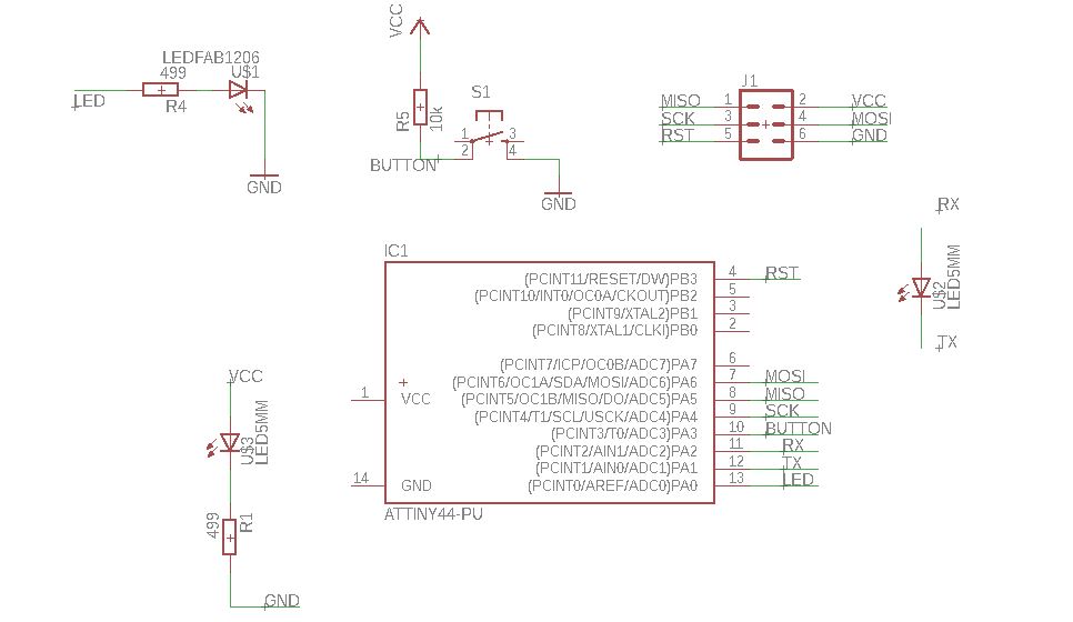
Finally, we run out of chips. That led me to the choice of using the block/breadboard Attiny44 package on a milled board. The design includes a Attiny44 block version (from fab library), a LED and a button. The LED near the programming header is there just to provide two holes for VCC and GND. Here the schematics are shown.
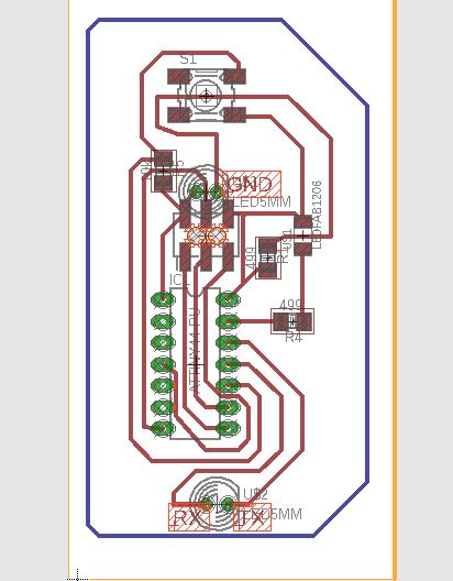
And the board, with all the components organized and connected.
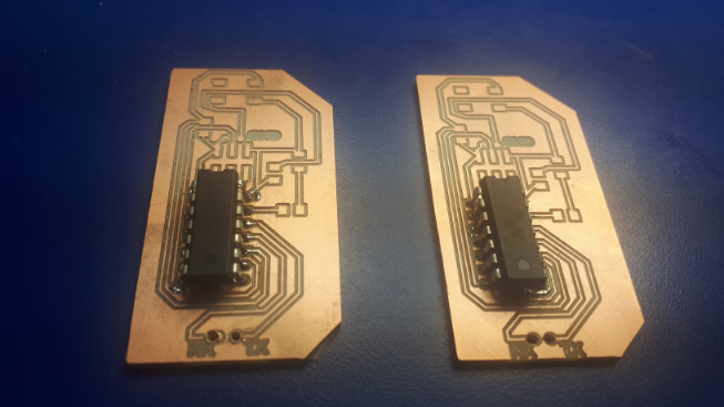
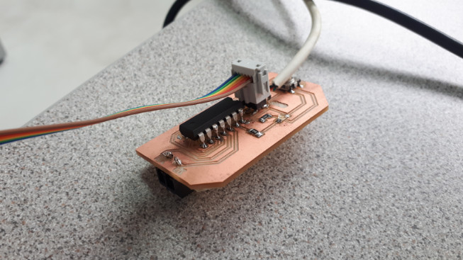
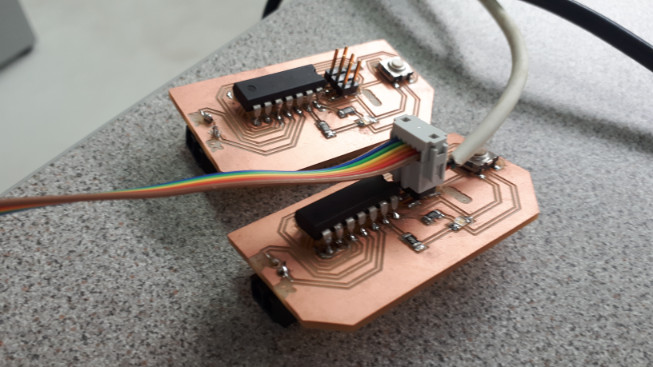
Once milled, the chips are located in place in both, tween boards.
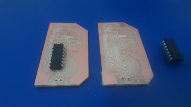
They are identical. The rest of the components are then added.
For testing, the blink programm is loaded in one of the boards.
And the same process is repeated in the other.
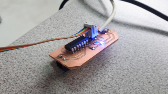
And here are they, the second beeing programmed.
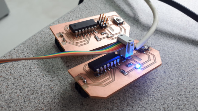
Here is a video showing one board transmiting to the other after pressing a button.
Software and hardware
The software used in this practice is linked in the text.
The links are also here:
Transmiting chip TX.
Receiving chip RX.
The hardware for the board(s) used in this page can be found here:
Transmiting and receiving chip TX. Both boards are identical.
Assigment update: I2C Communication.
For this assigment, a form of addressing was required. I experimented with this technology using two prototiping boards, an Arduino Leonardo and an Arduino UNO.
The first step was to to test if the communication would work. I2C Uses two wires, one for Clock (Serial Clock Line, SCL), and one for Data (SDA). Both wires are set at logic high using pull-up resistors. The details of this type of communications can be found in the Datasheet of the device we are going to use.
In the following picture we see the configuration. One microcontroller serves as a Master and the devices ADC, DAC and another microcontroller serve as slaves. The pull-up resistors are marked Rp. They keep the signal of the data (SDA) and clock (SCL) wires activelly high.
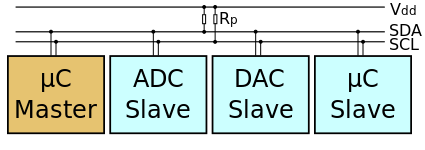
By en:user:Cburnett - Own work made with Inkscape, CC BY-SA 3.0, Link
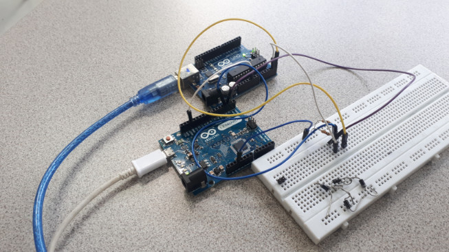
The first step was to test the communication and assinging/infering the addressing. I did so by loading a scannning script in an Arduino Leonardo, and an slave script in an Arduino UNO. Here we can see the devices connected.
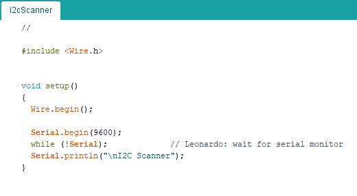
Scanning code:
The scanning script beggins with an inclusion of the Wire.h library, that manages the communcation protocol. Then, in setup() we inicialize it with Wire.begin. Also, the Serial communication to see the results in the Serial monitor.
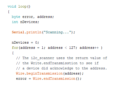
Then, in the loop() function we declare two variables type byte, called error and address, and a integer variable called nDevices. In a for loop, we go through the possible devices addresses, from 0 to 126 (127 in total). For each, we call the Wire.beginTransmission with the Address argument. With the function Wire.endTransmission() assigned to the variable error.
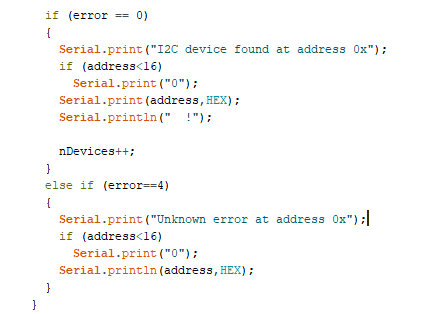
Then, the conditional if the error is equal to 0. If so, a subrutine is excecuted indicating the address found in HEX (hexadecimal), format. If the error is equal to 4, the "unknown" error is executed.
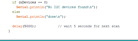
Finally, if the variable nDevices reaches 0, a message with indicating that not devices were found is shown.
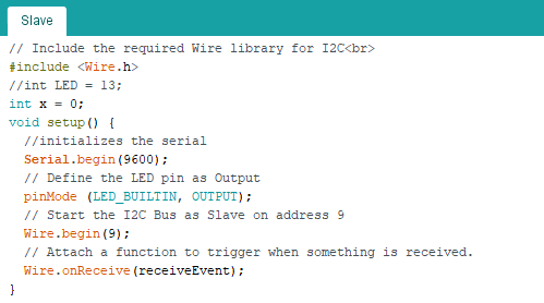
Slave code:
In the slave code, we also include the Wire.h library, and declare an x variable to hold our data before the setup() function. Then, in setup(), We inicialize our Serial, declare the builtin pin as output, and use Wire.begin, but this time assigning a 9 as the device address (in this case, as slave, it needs it). Finally, if an event is received, as looked up by the function Wire.onReceive, we trigger the function receiveEvent, that will be described next.
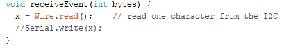
The receiveEvent function has a integer bytes argument for the datatype. It has just one line, that assigns what is red by the function Wire.read() to the variable x.
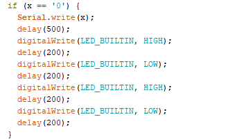
Next, we have an if conditional. If our variable x equals "0", we print it in the Serial monitor and run a series of ons and offs in the builtin led.
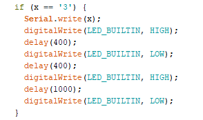
We also have other routine in the case the data transmited is "3".
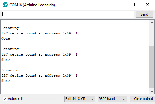
Then, we run the code, and see that the slave device is found, with the address 0x09, hexadecimal for the "9", address that we assigned to the device.
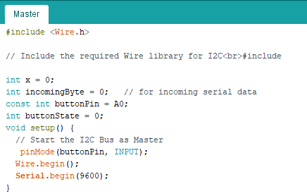
Master code:
Finally, we replace the following Master code to the device that had the scanning script. We included a button in this case, and keep the code for Wire.h and Serial.
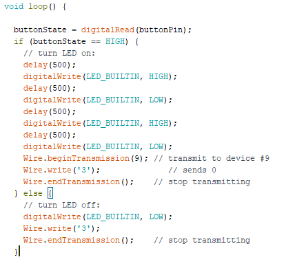
In the loop() function, we turn the led on and off a few time before transmission, so we can see it better.
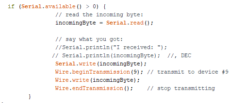
Also, an input for the Serial monitor is included. This will be used for triggering the led in the slave device with different data.
Once uploaded, we can see the result using the button...
And using the Serial monitor as input. In this case, a "0" triggers the first if conditional, a "3" triggers the else if conditional, and a 4 does nothing.
The code could be uploaded to the machined boards shown previously, with modifications in the code that addapts to the nature of the Attiny series. The code used in this demonstration can be found in the following links:
I2C Scanner, For scanning i2c addresses,
Slave, for programming a slave device,
Master, for programming a master device.
