Week 6 assignments:
Electronics Design:
From Fab Academy 2018 assignments
1. group project: Use the test equipment in your lab to observe the operation of a microcontroller circuit board.
2. individual project: Redraw the echo hello-world board, add (at least) a button and LED (with current-limiting resistor), check the design rules, make it (if you have time this week, test it)..
Have:
Shown your process using words/images/screenshots
Explained problems and how you fixed them, including how you worked with design rules for milling (DRC in EagleCad and KiCad)
Included original design files (Eagle, KiCad, Inkscape, .cad - whatever)
Redraw the echo hello-world board, add (at least) a button and LED (with current-limiting resistor), check the design rules, make it (if you have time this week, test it)
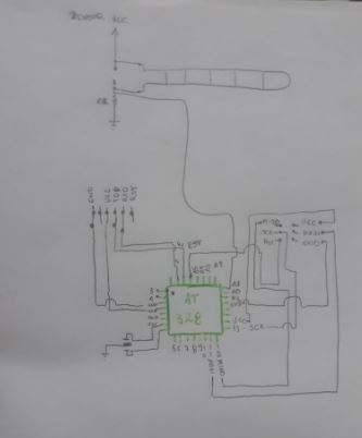
I have some years using the eagle software for the design of electronic circuits, for this activity I designed a circuit that I will use to perform the first sensor measurement tests to be used in the final project and in compliance with the assignment of the this week add a push button and an LED on the same circuit.
EAGLE
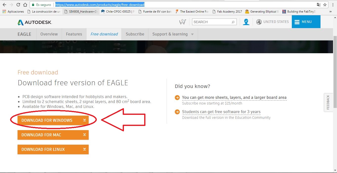
EAGLE is a scriptable electronic design automation (EDA) application with schematic capture, printed circuit board (PCB) layout, auto-router and computer-aided manufacturing (CAM) features. EAGLE stands for Easily Applicable Graphical Layout Editor (German: Einfach Anzuwendender Grafischer Layout-Editor) and is developed by CadSoft Computer GmbH. The company was acquired by Autodesk Inc. in 2016. You can download the student version of the eagle software from the Autodesk website. To download press Here
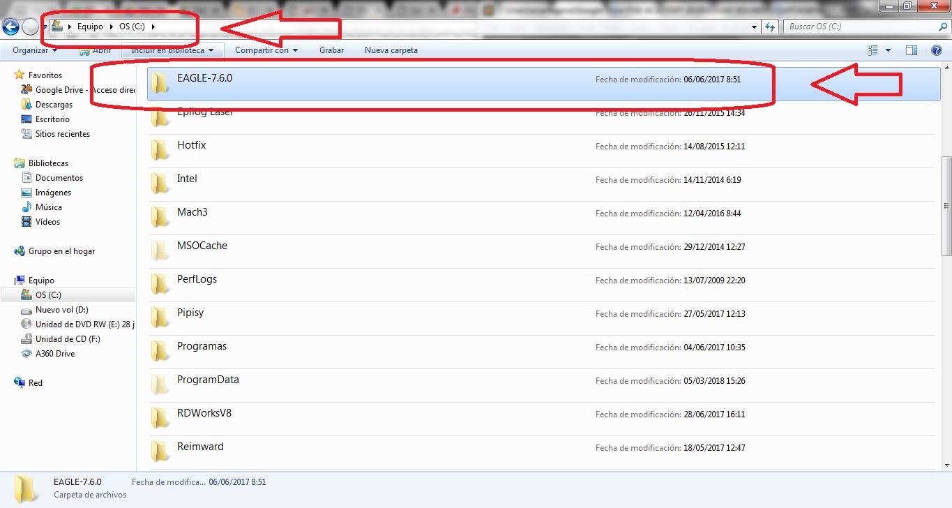
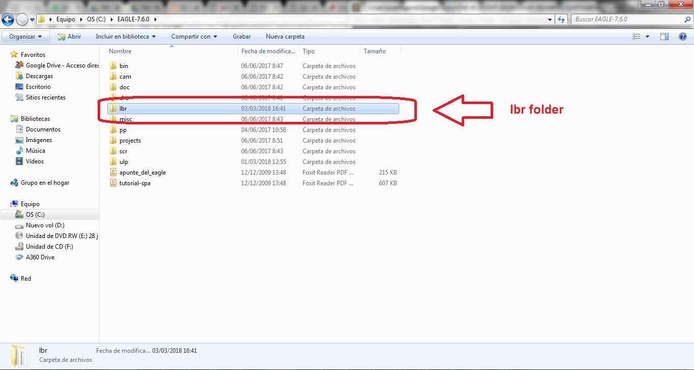
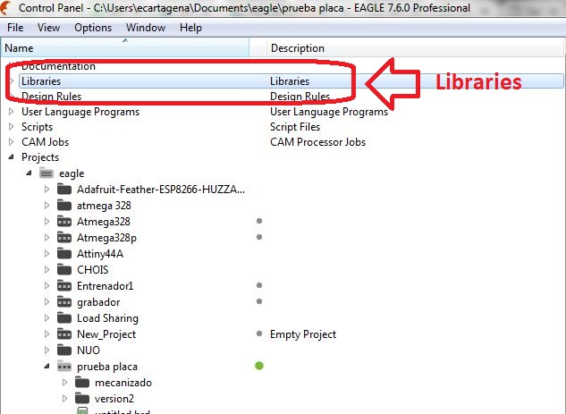
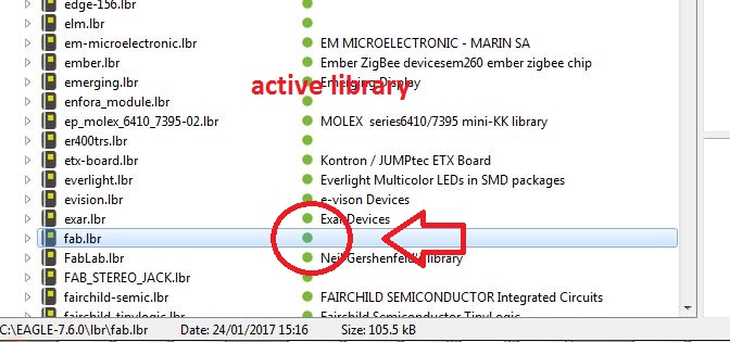
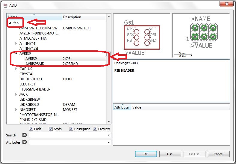
Before starting to design the electronic circuit it is necessary to download some libraries of the electronic components used, for this there is a library named Fab.lbr that contains several SMD components. So First you need to download and install the Fab component library. the library can be downloaded at the following link, then we must unzip the fab.lbr file inside the lib folder located in the eagle software installation folder.
Download and Install Fab library
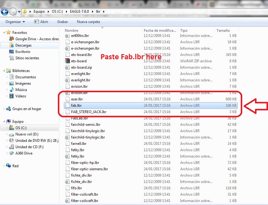
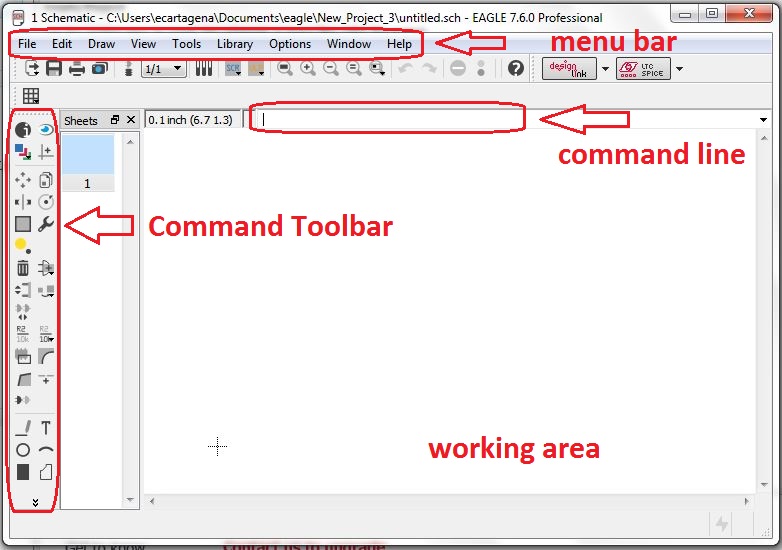
Now the software is ready to start designing the electronic circuit with the fab components, for this we must build a new project and then generate the schematic diagram
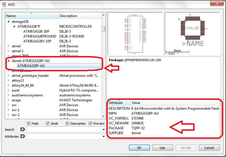
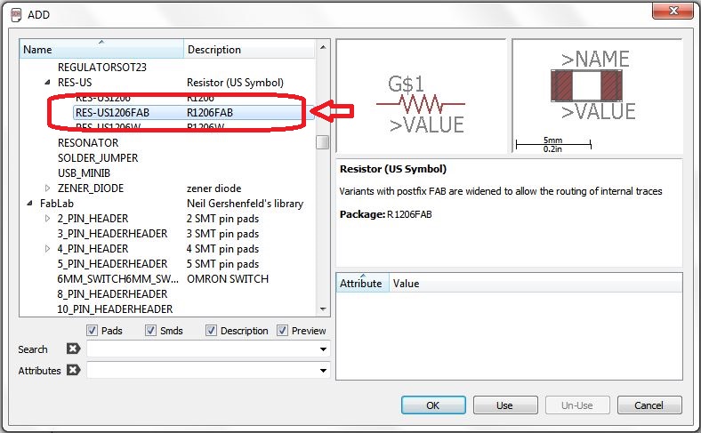
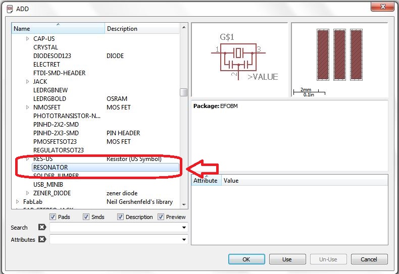
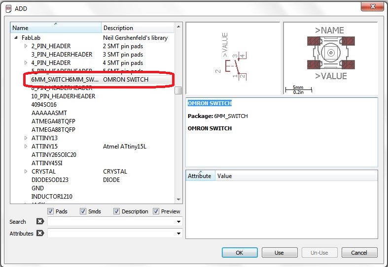
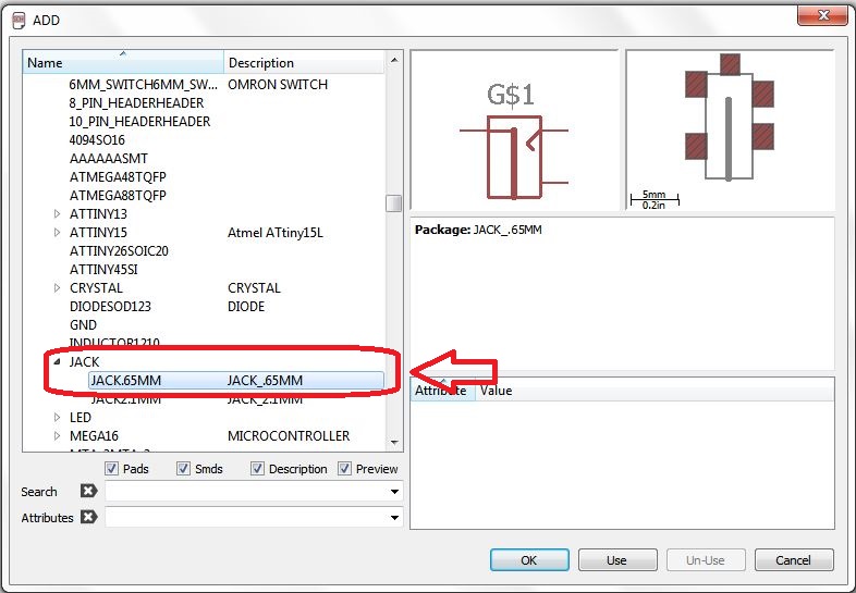
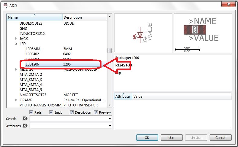
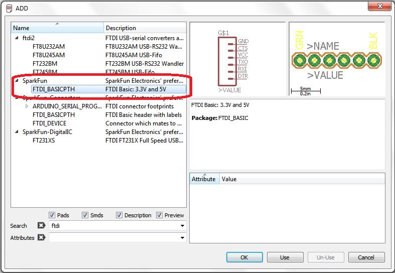
Electronic components used in the circuit
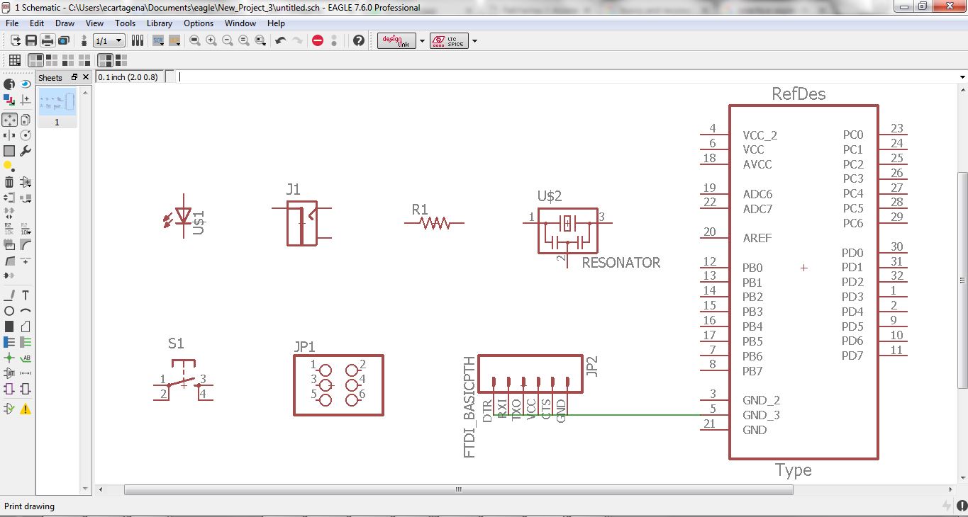
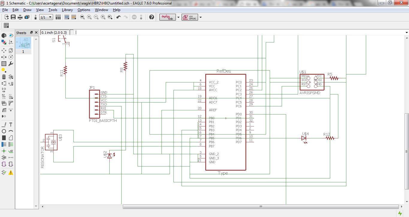
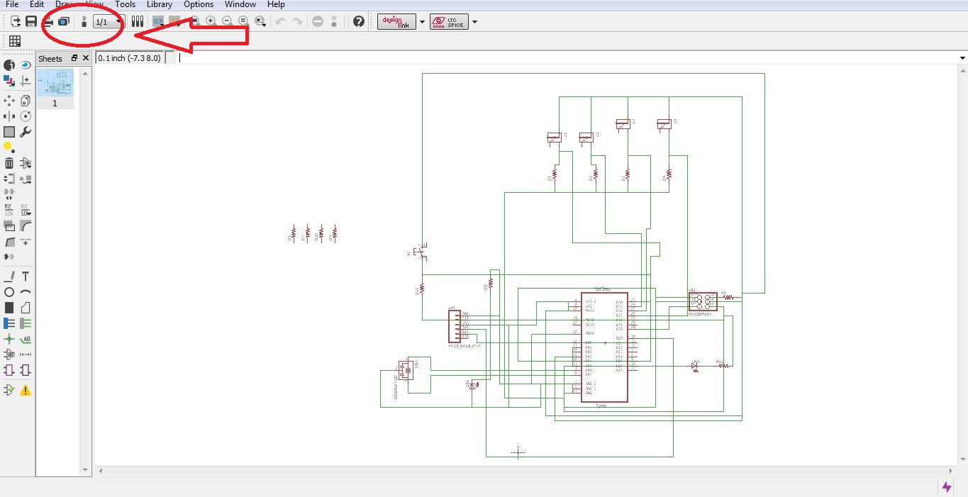
Make the schematic diagram of the circuit
Generate PCB BOARD
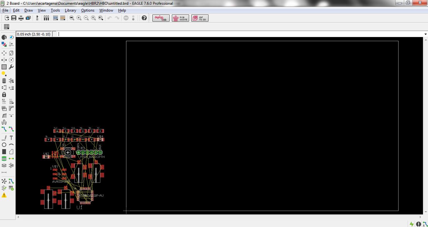
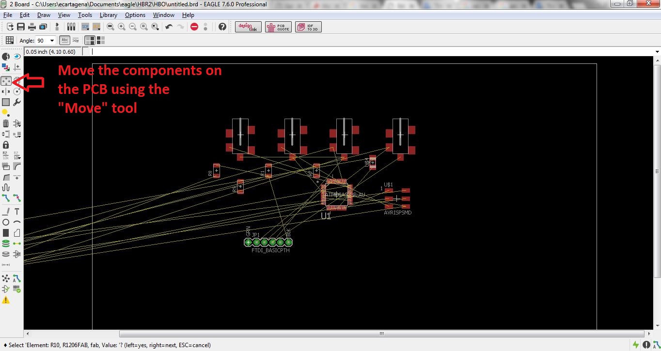
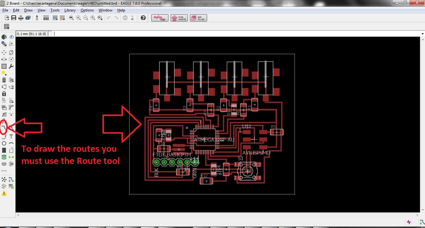
Locate components and make tracks of the circuit
Debugging the circuit
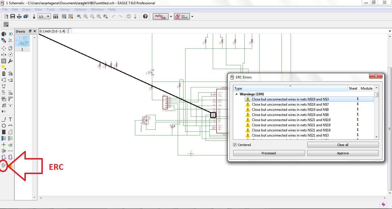
To verify that your circuit does not cointain errors or mistakes it is prudent to run the Electrical rules checker "ERC". You will find it under Tools-ERC or as it's own button on the side.
Below is the resulting errors list.The error close but unconnected wires happens if you use the "line" tool to draw the connections instead of the "route" tool. In this case, this does not affect the correct functioning of the circuit board, so no change is necessary.
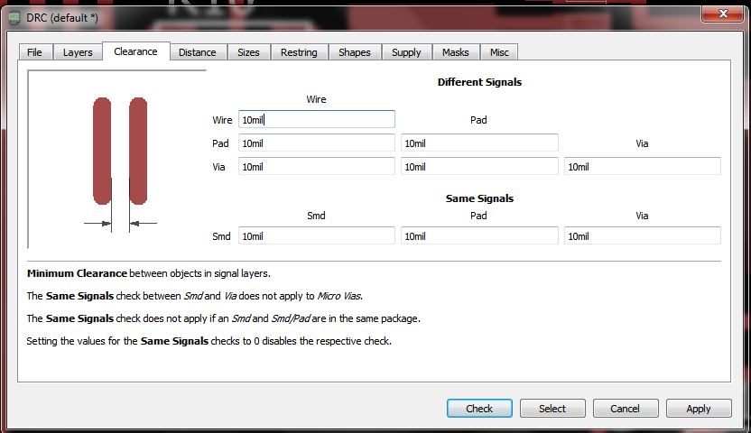
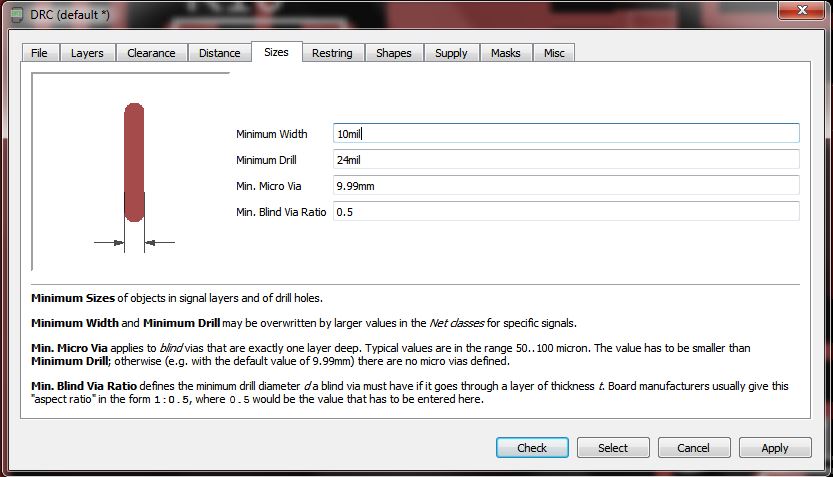
Design Rules Checker (DRC) Settings for milling
I setup the Design rules to work with outØ0,4mm milling bit. Meaning that all gaps must be at least 0,2 mm or 10mil (10/1000 inch).
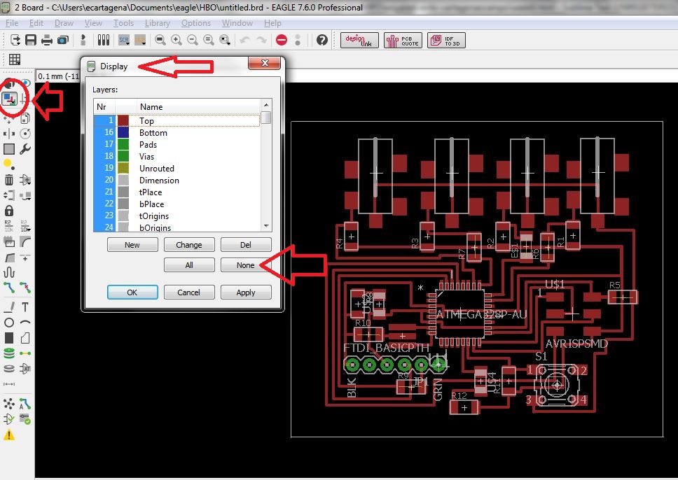
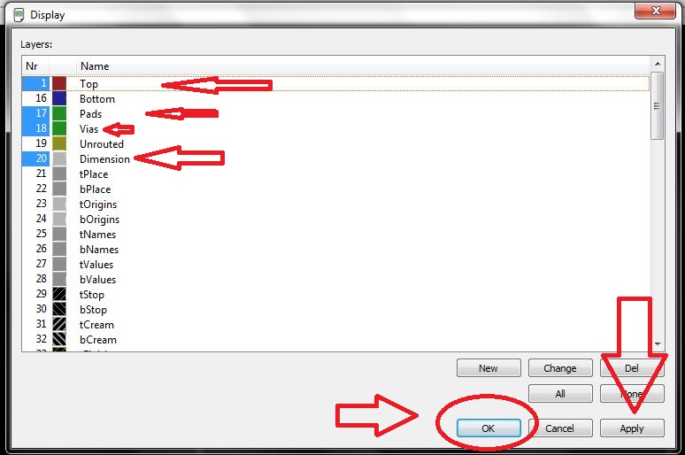
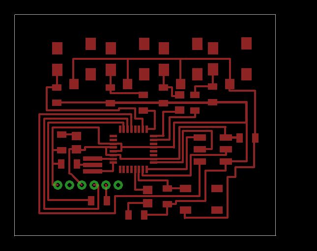
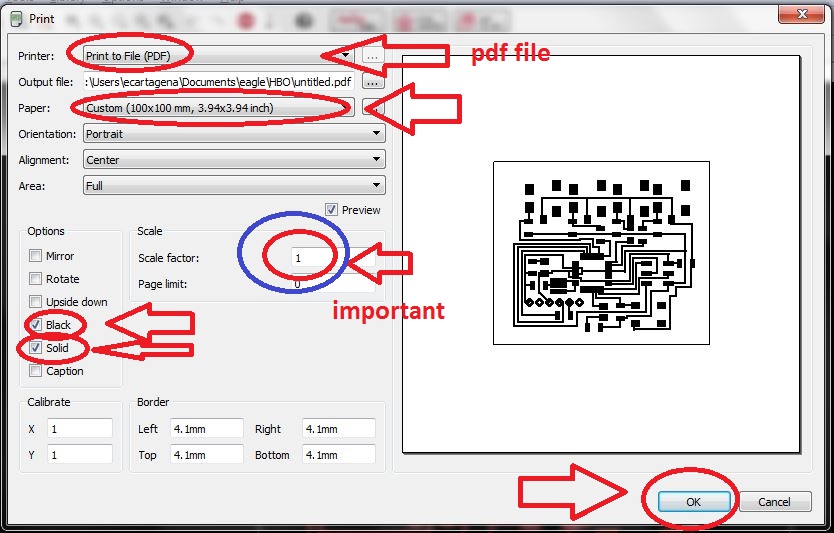
Generate cut and traces files
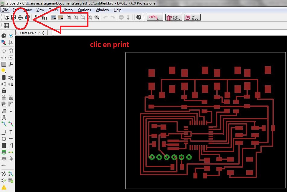
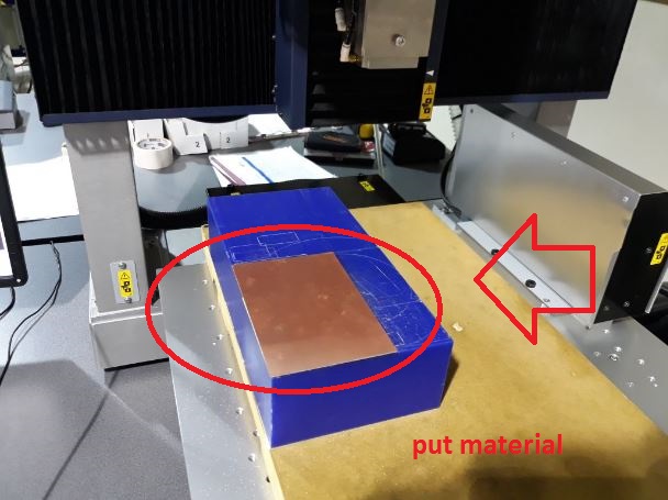
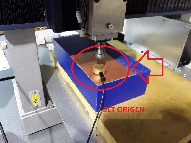
Fabrication
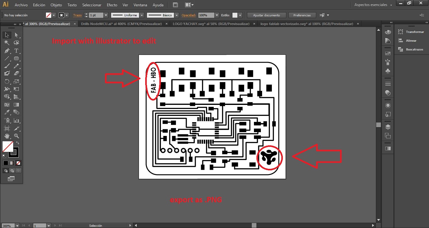
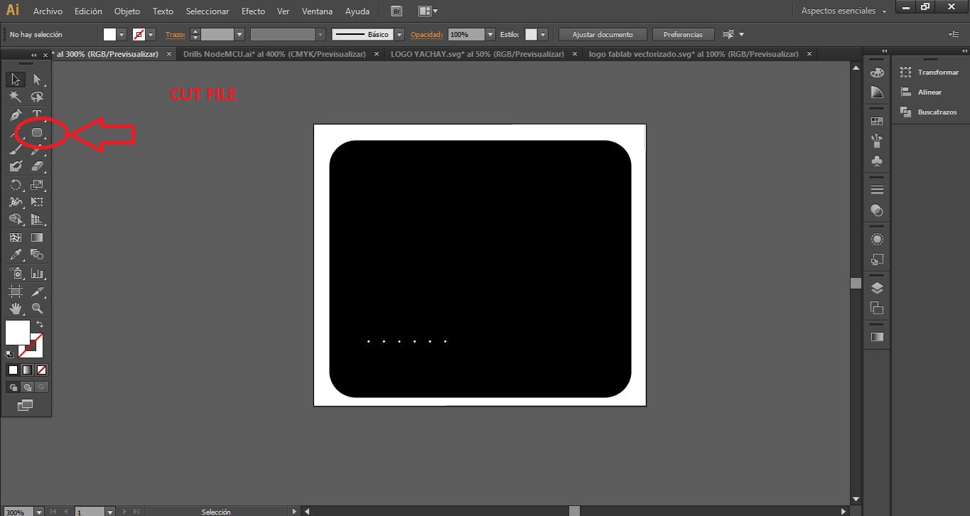
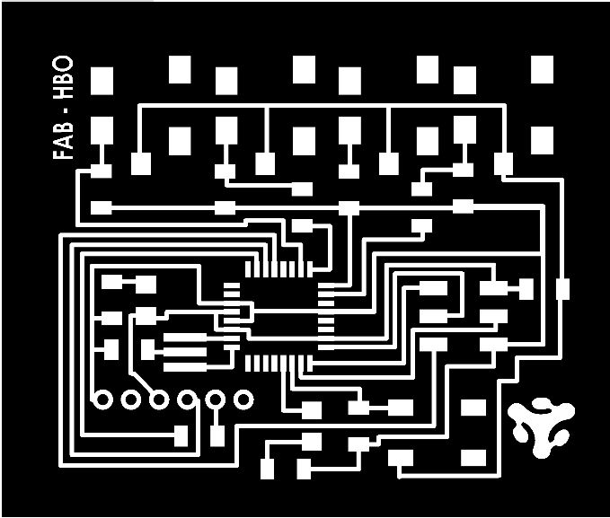
Generation of CNC cutting and milling files
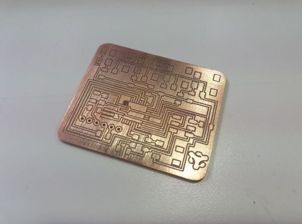
MILLING
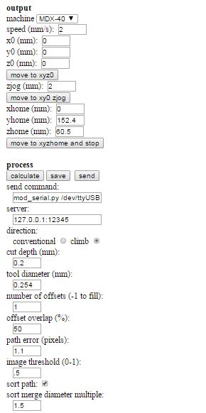
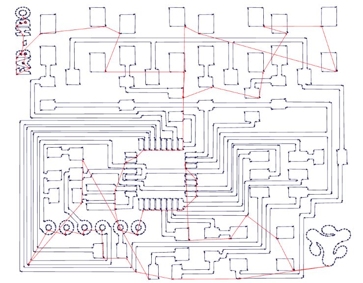
CUTTING
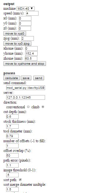

PCB manufacturing in Roland MDX 540 CNC milling machine, the configuration process of the machine you can see in the week of Electronic Production

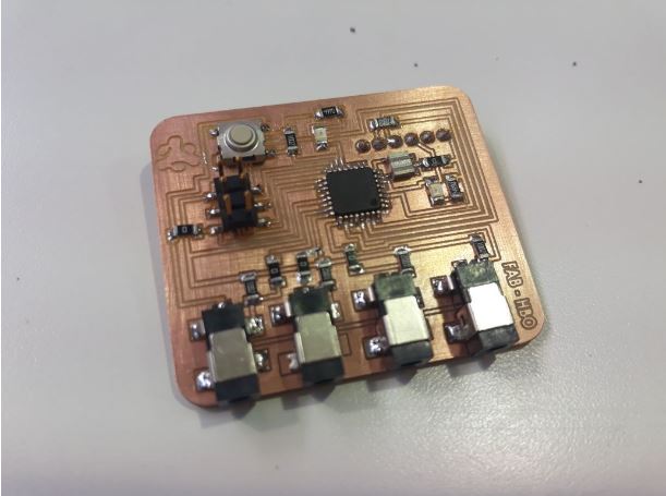
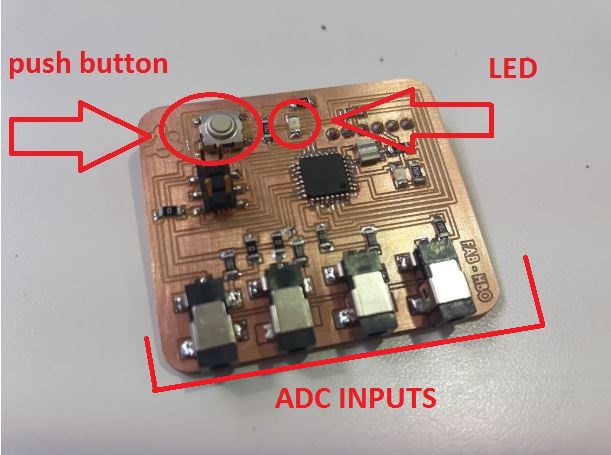
Adding the LED and button
I complied with the activity of this week the same one that requests add (at least) to button and LED (with current-limiting resistorI also added some sensor inputs connected to the ADC pins of the microcontroller to make programming tests related to the final project
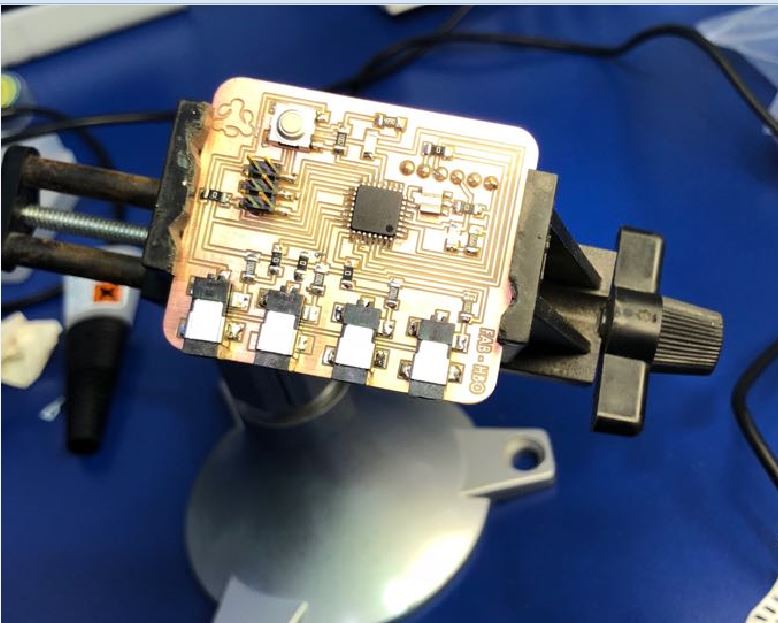
Group project: Use the test equipment in your lab to observe the operation of a microcontroller circuit board
For the group project we have made some tests of the electronic circuit making use of the oscilloscope and the multimeter.
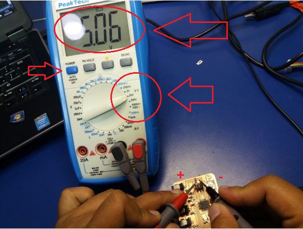
MULTIMETER
Multimeter is an electronic measuring instrument that combines several measurement functions in one unit. A typical multimeter can measure voltage, current, and resistance. This instrumen is common in electronic and electricity
Testing voltage with multimeter
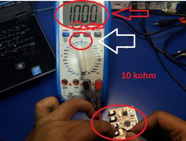
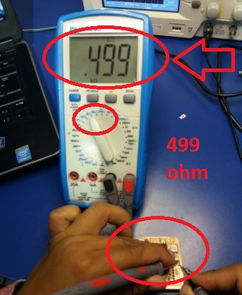
Testing resistors value
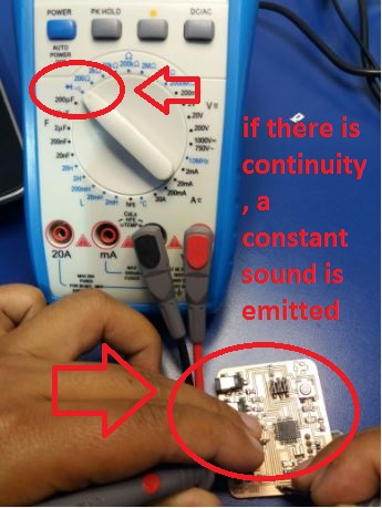
Testing continuity
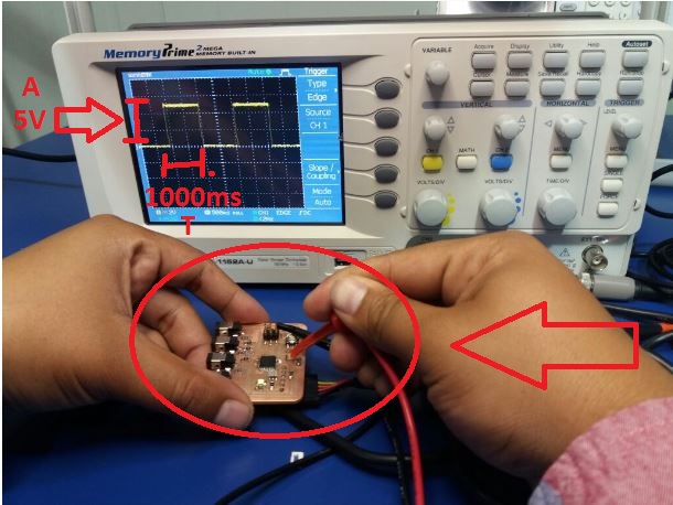
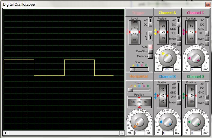
OSCILLOSCOPE
Oscilloscopes are used to observe the change of an electrical signal over time, such that voltage and time describe a shape which is continuously graphed against a calibrated scale. The observed waveform can be analyzed for such properties as amplitude, frequency, rise time, time interval, distortion and others. Modern digital instruments may calculate and display these properties directly.
Digital signal analysis with oscilloscope
Extra Activity
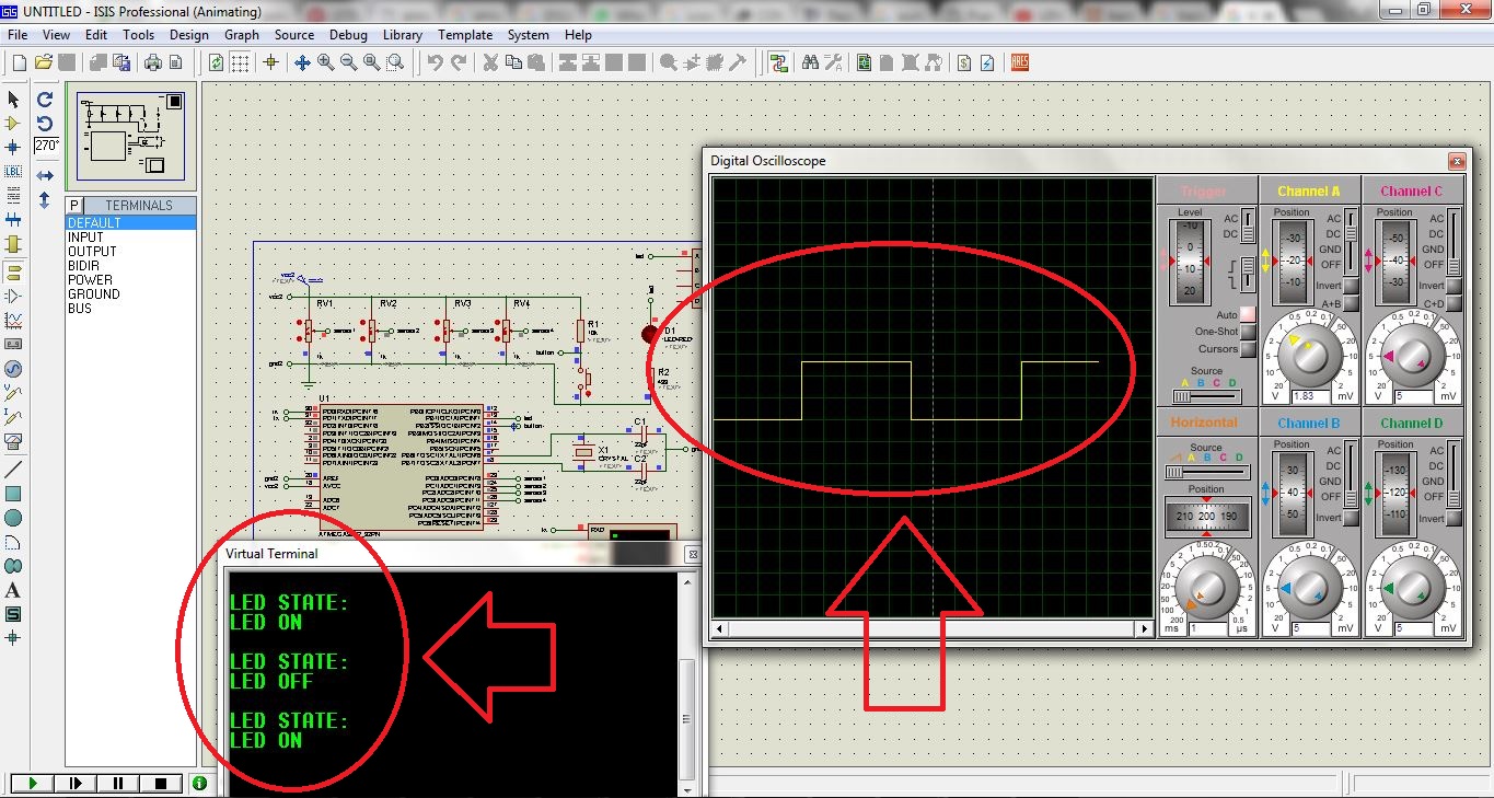
Simulation with the ISIS Proteus software
As an additional activity I use the software ISIS proteus. This program allows you to test the circuits and their operation by making a very accurate simulation.
In this case I made the simulation of the hello world program, and modified it so that by means of serial communication it indicates the LED status.
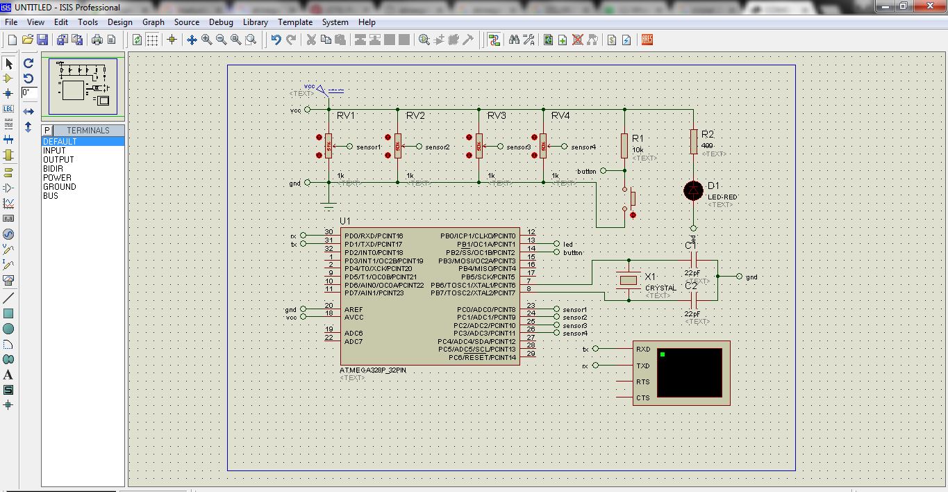
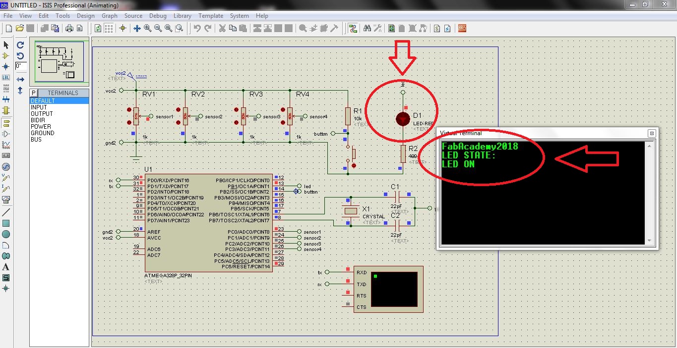
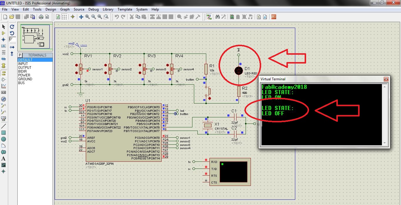
This software also allows to make measurements and analysis of the circuit in a virtual way like measuring voltages, currents, and other things more.

DOWNLOADS
- File 1: Cutting and Traces Files
- File 2: Eagle Files