Week 10 assignments:
Input devices:
From Fab Academy 2018 assignments
1. Measure the analog levels and digital signals in an input device (GROUP PROJECT).
2. Measure something: add a sensor to a microcontroller board that you have designed and read it..(INDIVIDUAL PROJECT)
Have:
Described your design and fabrication process using words/images/screenshots.
Explained the programming process/es you used and how the microcontroller datasheet helped you.
Explained problems and how you fixed them
Included original design files and code
Electronic Circuit
For the assignment of the week I designed and manufactured a new electronic circuit. This circuit is based on the attiny 44 microcontroller and I use the Arduino IDE to program the analog analogous reading to read the sensors.
Design of the electronic circuit in Eagle software.
The design was made in the eagle software but before starting with the design check the datasheet of the microcontroller mainly to know the distribution of the pins and their functions.
After reviewing the datasheet and knowing the characteristics and requirements for the design with the attiny44 microcontroller, make the schematic of the circuit
In this case I designed a board with an analog input for reading flexible sensors that are the ones I will use in my final project, A flex sensor or bend sensor is a sensor that measures the amount of deflection or bending. Usually, the sensor is stuck to the surface, and resistance of the sensor element is varied by bending the surface. Since the resistance is directly proportional to the amount of the blessing it is used as a goniometer, and often called flexible potentiometer.
It is also important to review the sensor datasheet to know its characteristics and performance, to download the datasheet click here
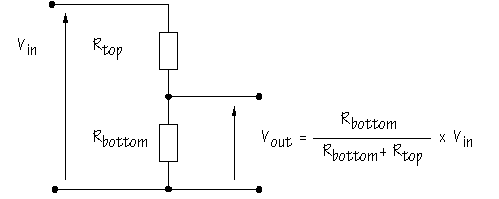
To have a correct measurement of the sensor we must design a voltage divider using the following formula:

Basic outline of the circuit
After the basic scheme I made the scheme in the eagle software where I added the isp post to load the program to the microcontroller and also added a port to have serial communication.
Electronic components used in the circuit
Locate components and make tracks of the circuit
I edit the circuit design using the illustrator software and customize it to then proceed with the manufacturing.
Then I use fab modules to generate the milling and cutting files.
For the manufacture of the plate I use the Roland MDX 540 CNC milling machine, all the previous configurations can see in the week of electronic production
Programming
Implement and interpret programming protocols
For programming I use the Arduino IDE
#include < SoftwareSerial.h >
int dato=0;
SoftwareSerial mySerial(A0, A1); // RX, TX

void setup() {
  mySerial.begin(9600);
  mySerial.println("Hello, world?");
  pinMode(6, OUTPUT);
  pinMode(2, OUTPUT);
  pinMode(3, OUTPUT);
  pinMode(4, OUTPUT);
  pinMode(5, OUTPUT);
}

void loop() { // run over and over

   dato= analogRead(A7);


    mySerial.println(dato);


  if (dato >= 493 && dato < 523  ) {

    digitalWrite(5, 0);
    digitalWrite(6, 0);
    digitalWrite(4, 0);
    digitalWrite(3, 0);
    digitalWrite(2, 0);
  } else {
    if (dato > 523 && dato < 553) {
      digitalWrite(5, 1);
      digitalWrite(6, 0);
      digitalWrite(4, 0);
      digitalWrite(3, 0);
      digitalWrite(2, 0);
    }

    else {
      if (dato > 553 && dato < 583) {
        digitalWrite(5, 1);
        digitalWrite(6, 1);
        digitalWrite(4, 0);
        digitalWrite(3, 0);
        digitalWrite(2, 0);

      }
      else {
        if (dato > 583 && dato < 613) {
          digitalWrite(5, 1);
          digitalWrite(6, 1);
          digitalWrite(4, 1);
          digitalWrite(3, 0);
          digitalWrite(2, 0);
        }
        else {
          if (dato > 613 && dato < 643) {

            digitalWrite(5, 1);
            digitalWrite(6, 1);
            digitalWrite(4, 1);
            digitalWrite(3, 1);
            digitalWrite(2, 0);
          }
          else {
            if (dato > 643) {
              digitalWrite(5, 1);
              digitalWrite(6, 1);
              digitalWrite(4, 1);
              digitalWrite(3, 1);
              digitalWrite(2, 1);
            }

          }

        }

      }

    }

  }


}

DOWNLOADS
- File 1: Cutting and Traces Files
- File 2: Eagle Files
