Work that Net! A background breifing...
Networking was one of the parts I missed during 2015 and picked up again in '17. The basis of this week is that we build a network that consists of at least two (2) processors communicating with each other. As I was quite lost I decided to document more for this week. And maybe future me won't be. Most of the following was tought by the fantastic Emma.
There are two kinds of Networks. Those that have wires, and those that don't. You can choose from:
Wired:
- single-ended, differential, powerline
- open collector, open drain
- transmission (pass) gate, tri-state
- transmission line
- waveguide
- TIA RS232, 422, 485
- 802.3 ethernet
- SONET
EFmaöegnaKGNÖkg
Wireless:
- RF -
- Optical
- Acoustic
Components for a Wired Network Circuit
- ATTiny-45 (or similar)
- ISP-header (for the programming)
- 4-pin header for RX/TX is only for the communication*
- FTDI - In order to communicate with the computer, works as a “bridge”
*the 4-pin can be removed if for example MISO and SCK are going to be used as RX/TX, thus the 6-pin header can also work for communication
Wired Communication Protocol
Asynchronous Serial - data is transferred without support from an external clock signal. RX (receiver) /TX (transmitter) Asynchronous refers to that the micro controller work on their own clock and don’t have a shared clock. With no clock we need to set up rules.
These rules include: Databits (highs and lows in signal), Synchronised bits, Parity bits, baud rate/“bps” bits-per-second (the speed at which the data is sent over a serial rate)
SPI - Serial Peripheral Interface
A “Synchronous” data bus. One sets a “Master” and a “Slave”. The “master” is the one that shares its own clock and the other one(s) receives the clock. A master can have many slaves but a slave can’t have many masters. To communicate the master has a separate channel for each slave. In other words, 1 pin per slave. This means that there is a physical limitation to how many slaves there can be, the maximum amount is thus determined by the size of the processor.
I2C Communication
I2C solves the SPI communication issue. With I2C one only needs 2 wires and allows for control of up to 1008 components.
The master starts communicating to one of the Slaves. It sends a frame or package. The first frame is 8 bits and used to open the communication and select which slave to contact. Each slave has an adress. After contact has been established the master can send instructions.
The Slave knows when to listen because of the starting condition. When there’s no information the signal is high. This is why there’s a pull up resistor. Thus when the signal is low, all the slaves notice that a transmission is about to start. This is the starting condition.
The pull-up resistor is connected both for the SDA and SCL between the connection of Master and Slave. The value is commonly 4.7kOhm.
Out of the 8 bit transmission there is one Read/Write bit, if R/W bit is set to 1 the Master is requesting Data, if 0 it’s sending Data. Another bit is called ACK, short for acknowledge. If this bit is set to 1 it indicates that the slave did not respond or was unable to process the request.
SCL = Clock
SDA = Data
My Networking Process
I wasn't quite sure what I wanted to do and could have easily gone over-enthusiastic in regards to the multitude of opportunities again. This time I took a chill pill in the form of LEDs and went for the easier but managable route.
Choosing Components
I decided to go with LEDs instead of the motor + momentary push button I was originally planning.
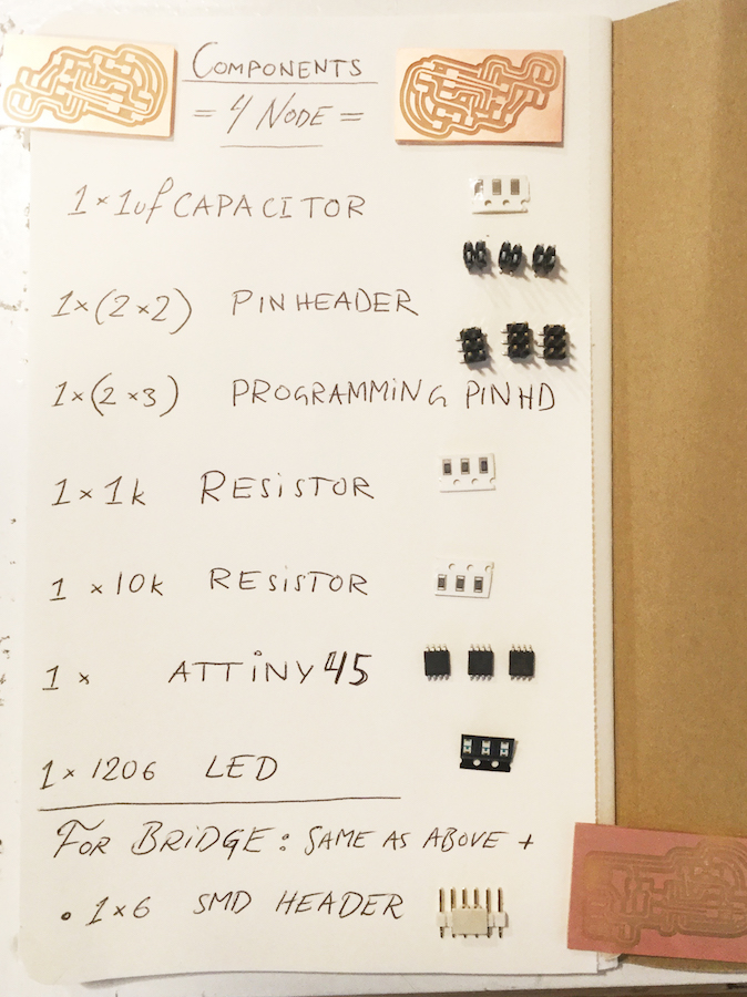
The full list of components can be seen in the image above or in the list below. As there are three boards to make I made them all at once.
For the Nodes
- ATTiny - 45
- Capacitor - 1uf - 1206
- Resistor - 1k - 1206
- Resistor - 10k - 1206
- PinHeader - 2*3
- PinHeader - 2*2
- LED, SMD - Blue - 1206
For the bridge I also included:
- FTDI Header - 6*1
P ate C but that was plan B
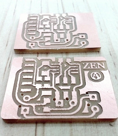
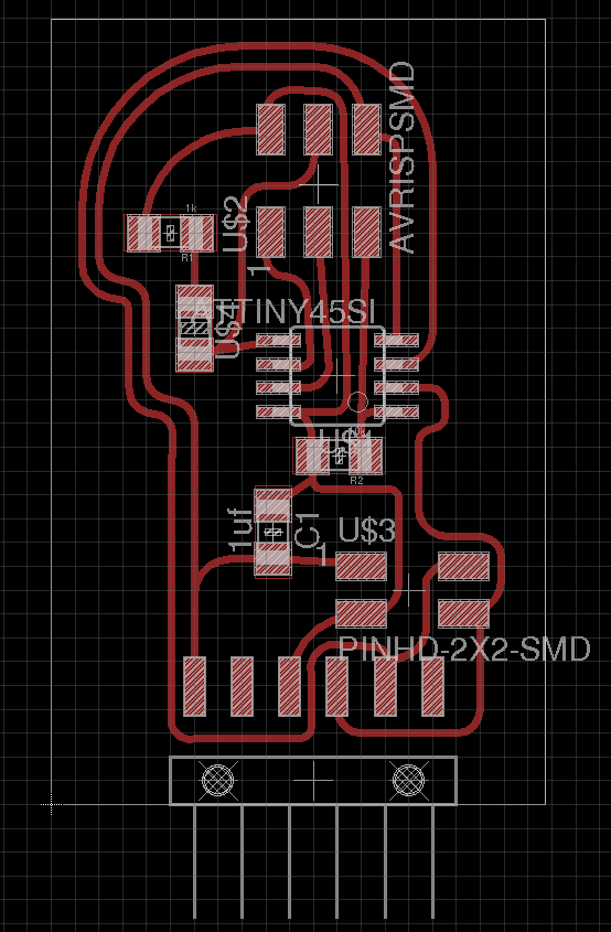
Designing the boards was fairly straight forward as there was multiple examples from previous students, for example the exeptional Norma. I did run into issues though and was fearing that I'd have to use a 0k res but it eventually worked out. I made the Bridge board first ( see image below ) based on 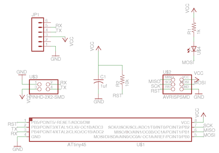 this schematic and then simply removed the FTDI header from the Bridge schematic to make the
 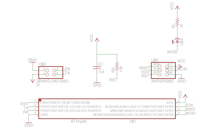 node schematic. The
 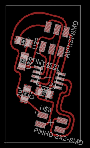 node board is similar to the Bridge as well.
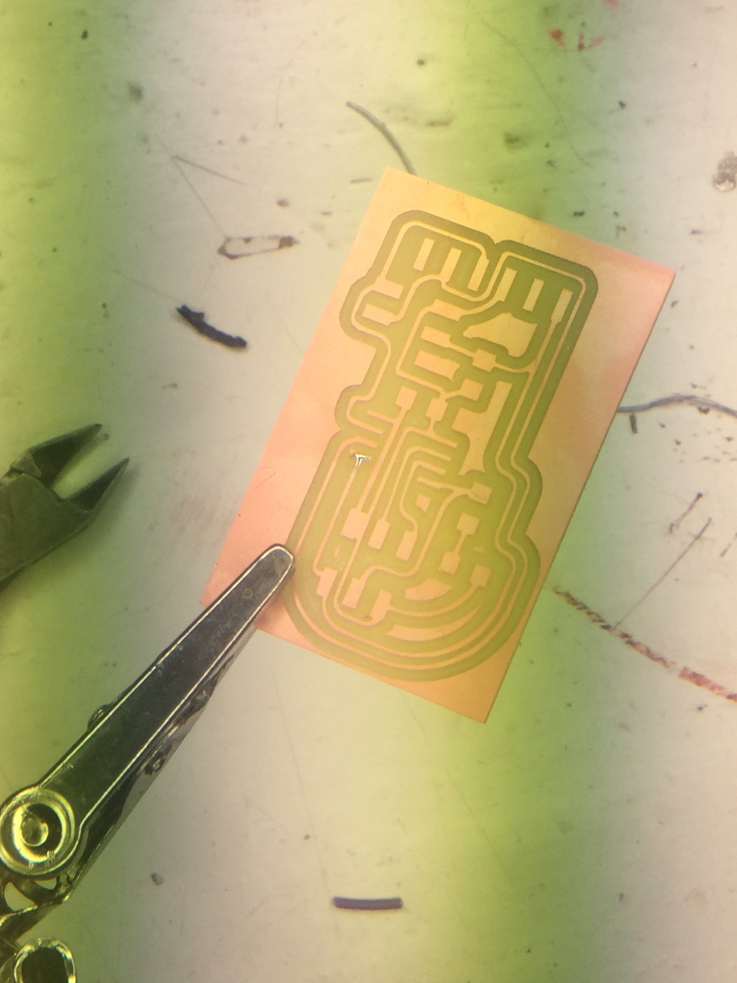
The actual milling went smoothly as I remembered to 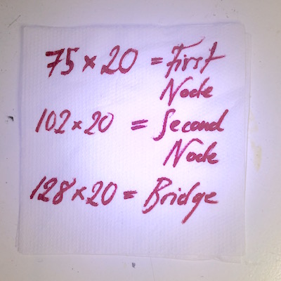 write down the coordinates.
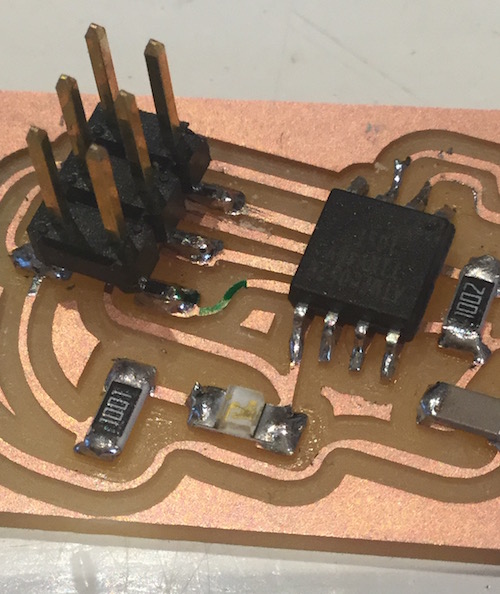
Next up was the soldering but that all went fairly straight forward. I noticed that the lines between the 6 pin header were a little too close but I solved this by stabbing the board multiple times until it gave in and worked. This happened twice per board. No big deal. Only a knife needed.
Another thing I learned and thrived from was a tip from Emma again, she recommended marking out pin number one on the 6 pin header in order to be able to keep track of the orientation when serial connecting the boards. Like this:
Next up we had the computer side of things. In order to get everything set up there was (for me at least) four steps.
Step 1) Download AVR, dude
I followed this tutorial.
Step 2) Check if the board is OK
...if not, stab it. I had to, as mentioned previously, stab my boards a bit, just to remind them who truly is the master. My helpful surveillor and reporter - the computer - was kind enough to let me know in seperate messages who and what was misbehaving. Firstly the programmer was acting up, 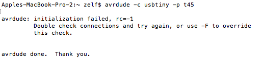 hiding from us in fact. After that we found the real culprit, the circuits! The computer told us so
 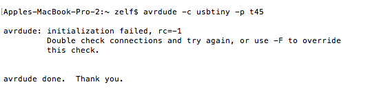 in a very modern manner. This required some bug finding. Our
 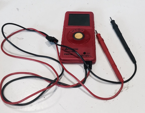 faithful friend helped out.
Step 3) Burn The Bootloader
In order to burn the bootloader we have to make sure we have the ATTiny's available in the 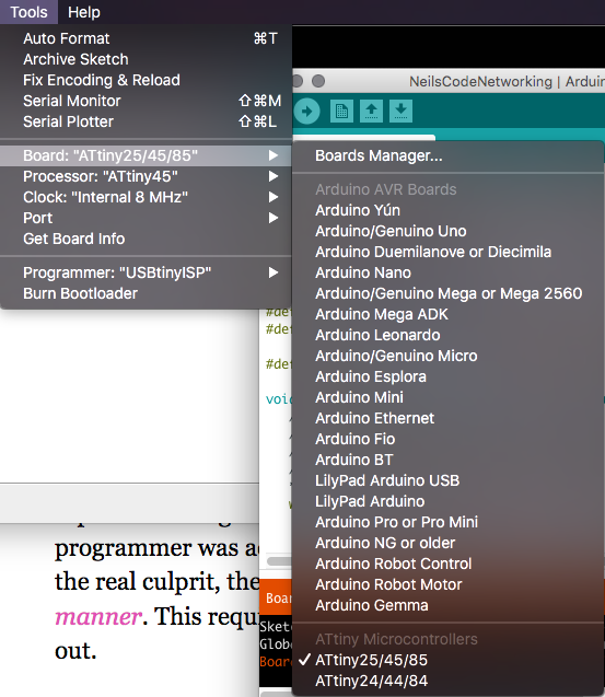 list of devices in Arduino. If the Attinys don't show one can add them by going into preferences and copying this link into
 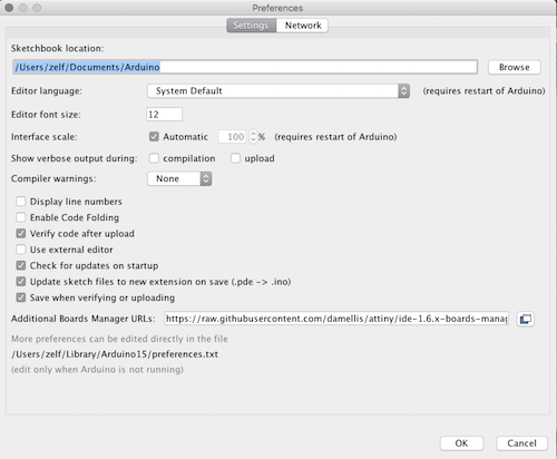 this box.
I ran into a bit of issues though and got 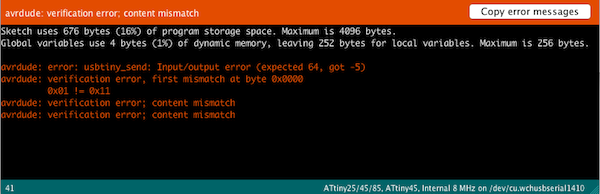 this error message. It turned out that the linked in devices only work on Arduino version 1.6.9 while I had 1.8.1. I downloaded the older version and got going.
To burn the bootloader we will keep the 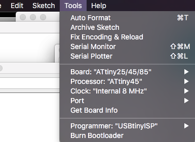 settings the same for all and then one simply presses "Burn Bootloader".
Step 4) Upload Neils Code!
Left now was only the last step. Uploading the code! I downloaded it and opened with xcode copying the code into arduino. I changed the id of the nodes and uploaded each seperately. I then opened 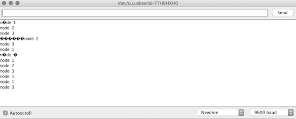 the serial monitor, set the
 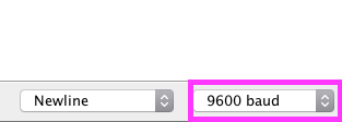 baud to 9600 and pressed 1, 2 and 3 which made the lights flare up!
Like this!
The wheels on the bus... (everything below this was written 2015)
For the communications project we worked collaborately to build several circuit boards which would communicate with each other. I'm just going to outline very quickly since the regional starts in around six minutes. I made a circuit board, 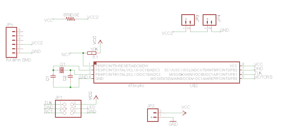 which looks like this, based of Craigs first outline. It was generally pretty similar to my previous motor boards with two exceptions.
First Exception
This one is simple. but as you can see 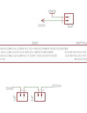 here there are screw terminals. It might seem superflous and if so it's because it is. I do however need at least two since I'm using two motors (as soon as I can get a hold of the second one). The reason I had a third was because I had been planning to power it by battery but ended up adding a header anyways rendering the screw terminal for the battery unnecessary.
Second Exception
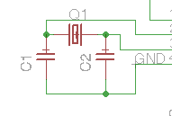 I used a crystal! Which I've never done before but according to Daniel it will be the best option for the connected boards. Other than that, so far, it's gone well. It was the first time ever I managed to make a board that
 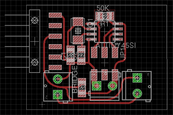 doesn't have any 0 resistors! (except for the bridge) so that made me happy.