
It works!
I had to make a few changes to the board and the script to make it properly work. For the board I had missed to connect the motor to the right pin as well as redo the math. I should never have trusted the original website I checked in week 7 since I knew it was bad from the start. Instead I ended up doing some other calculations and figured that I only needed a 49.9 ohm resistor. The old board looked like 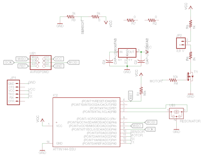 this and the new one like
 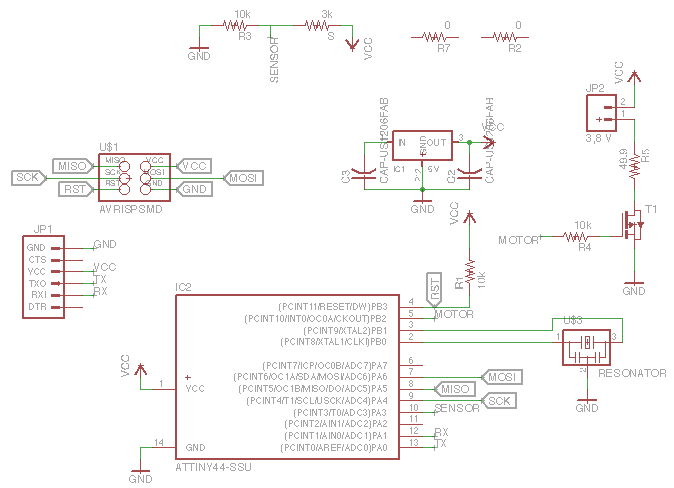 this.
this.
I SHALL FIX IT
The script was giving off error messages. The first one said 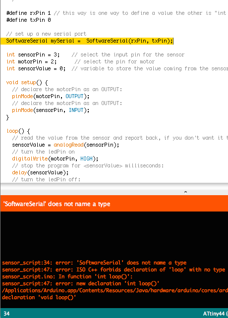 "Software Serial does not name a type" but I solved it by adding #include <SoftwareSerial.h>. I still had an
 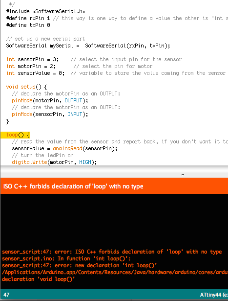 error regarding the loop command. This was solved by simply adding void (which I had originally accedentally deleted). After this it was
 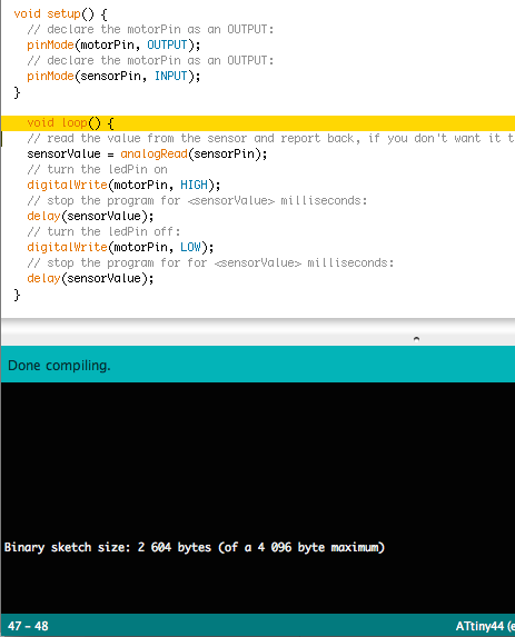 all good!
AND IT SHALL WORK
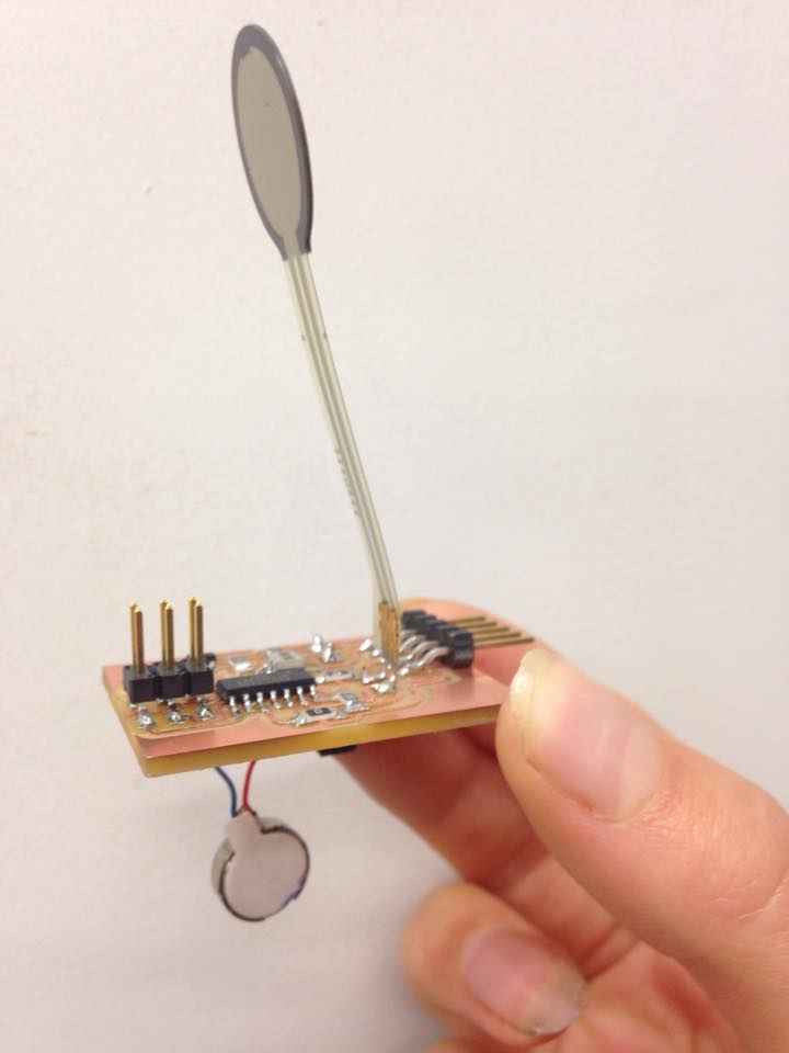
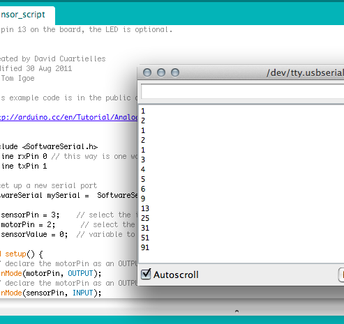
I knew that the sensor worked since it was giving showing the 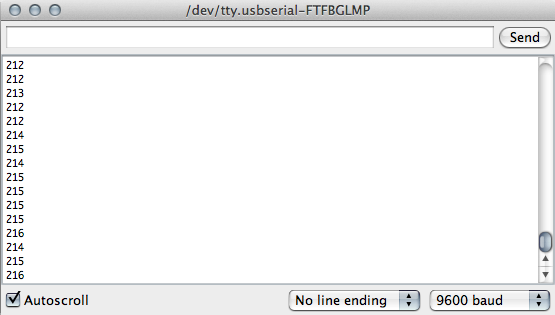 input well and the numbers I'd be expecting. The motor wasn't working though, even after I remade the board. It ended up being a really simple problem, I hadn't changed the pin in the code. It started with
  the PA2 pin from the old board and confusing enough it was
 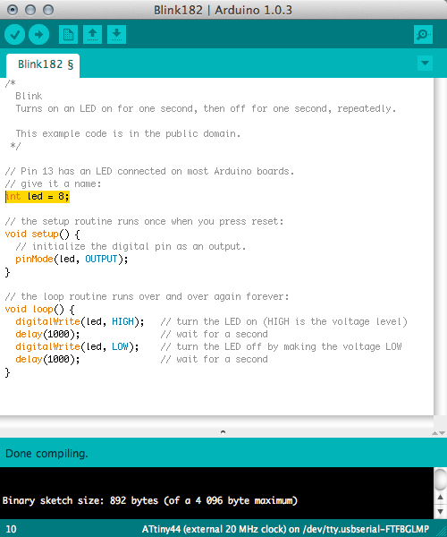 the PB2 pin on the second one.
Ohh Datasheets, how you saved me
A big favorite during my time working with the ATTiny series was 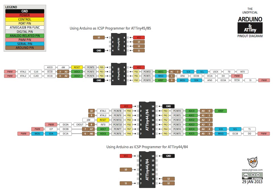 this datasheet. It saved me both when setting up the board and making sure I connected MISO to MISO on the scematics but also when checking which pins can be used for what. For example, if there's an analog read or a digital read pin. For example, the Pulse-Width Modulation (PWM) pins will be very helpful for when I connect the momentary push button.