Tasks of this week:
The weekly assignment started with the simple tasks:
1. Group Assignment:
compare the performance and development work flows for other architectures.
2.Individual assignment:
i.read a microcontroller data sheet
ii.program your board to do something,with as many different programming languages and programming environments as possible
1. Indivisual Assignment:
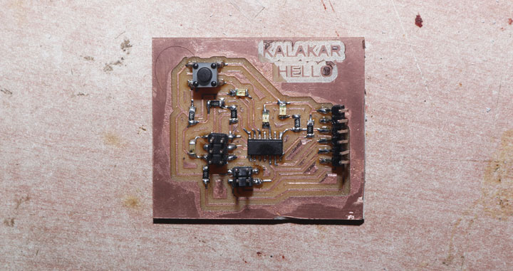
This week assignment was all about controllers, processors, etc. which will be programmed to do things. The most common microcontroller used in FabLab is the ATTiny Series. They are all AVR microcontroller's, and I will be programming the board I made in Electronics Design.I have made a echo-hello board with Attiny44 microcontroller which can be programmed using the FabISP. The board I made have a LED and a press button switch attached. So I can program the board to do some basic tasks like blinking the LED.
As I am from dffrent background, to study the data sheet my local instructor Arundhati helped me a lot.
Datasheet:
A Datasheet is a instruction manual for electronic components. It thoroughly explain exactly what a component does and how to use it. Unfortunately these documents are tightly packed with the information and hence can often be difficult and super confusing to read, especially for beginners like me. Datasheets are still the best place to find the details you need to design a circuit or get one working.The image shows the part number for which the datasheet is applicable for which is ATtiny series microcontroller devices. This data sheet which I was referring is applicable for ATtiny24A/ ATtiny44A/ ATtiny84A. The part number tells us that the given microcontroller is specifically a Atmel 8-bit AVR Microcontroller with 2/4/8K Bytes In-System Programmable Flash.

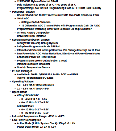
The Image shows that the Power conditions of the ATtiny.
It tells us that the ATtiny is designed for work between the voltage
of 1.8V to 5.5V. Then it tells about the clock speed that we
can use while voltage variations. The other special feature
tells about the different power saving options.
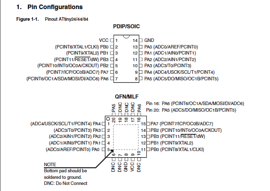
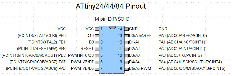
now it shows all the pin configuration of ATtiny 44.
This helps a lot to know how and where to connect any PIN
with a specific number while coding. It helped me a lot!!
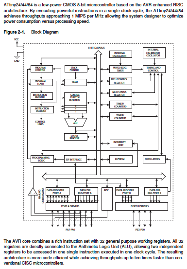
This is a block diagram of ATtiny 44.
Now the main task starts!! Programming!!:
In the task we have to program the echo-hello board, which we all have made
in Electronics Production week. as you can see the image.
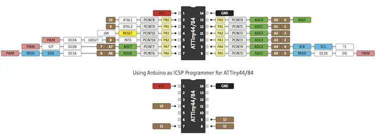
As usal I googled the pin configruation of ATtiny 44 and these are the
pin configuration of ATtiny 44 which I found.
First of all I downloded the ardiono IDE.
(IDE is a peripheral that communicates between the hardware and the
software interface having a very user friendly User interface. It has it's necessary command
arranged in a graphical way to make it easy and interesting for beginners like me!)
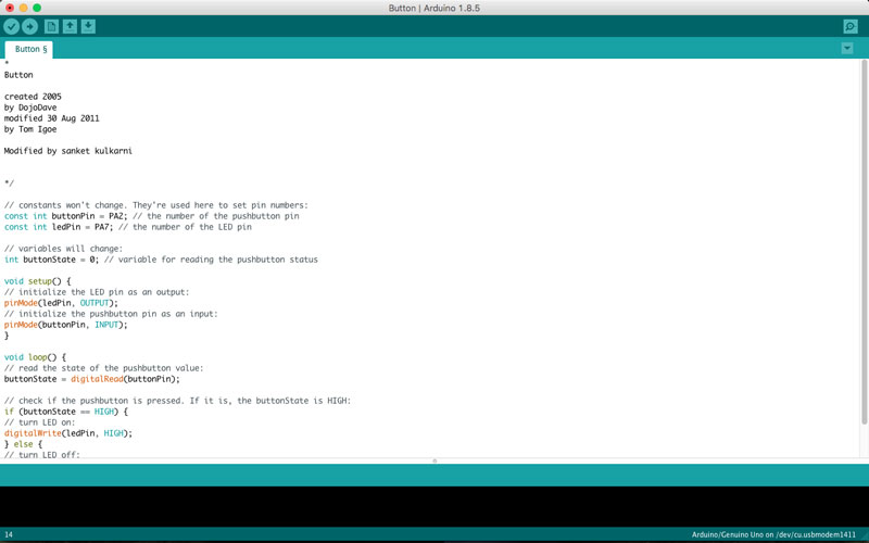
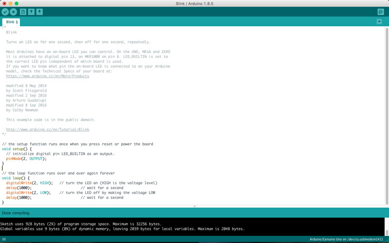
At the initial stage we have to blink a LED. so I thought to use my ISP which I have made erlier in weekly assignment. so to program my board I used my ISP through ardiono IDE. I opend the blink code from file-->examples-->basics-->blink. this is how it looks.
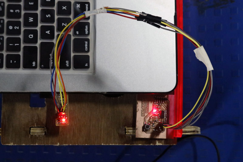
Then I connected the ISP to my echo-hello board with the jumpper wires. and then I connected the ISP to my laptop.
After that I changed few configurations in ardiuno IDE. following steps I did.:
1. Changed the baord to ATtiny 24/44/84
2. Processor I select ATtiny 44 becouse I have used that in my board.
3. Clock I changed to 8 MHz.
4. I select the port where I was connected the ISP.
5. Then I selected programmer as USBtiny ISP
After that I clicked on burn bootloader and burned the bootloader. and before clicking on verify I changed the and verified the code and clicked on update.
Yey!! and the LED started blinking all the way!!
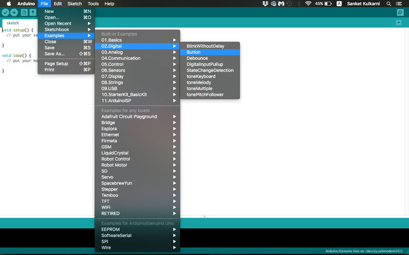
After this I wanted to run a button code I went to File -> Examples -> Digital -> Button, becouse I wanted to run the button program.
This program is a connecting the button to the LED via micro controller. you can see the elements of the program.
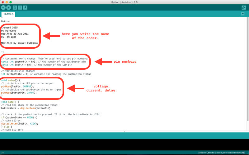
So I had modified the program and uploaded it to the board, by chaning the pin number as seen in the datasheet of the IC and my circuit diagram.
after pressing upload, "done uploading" came and the led on the board blinked.
You can Download the coding Files.
2. Group Assignment:
compare the performance and development work flows for other architectures.
for this week We had decided to explore the architecture, configuration and coding it through python.
Specification:
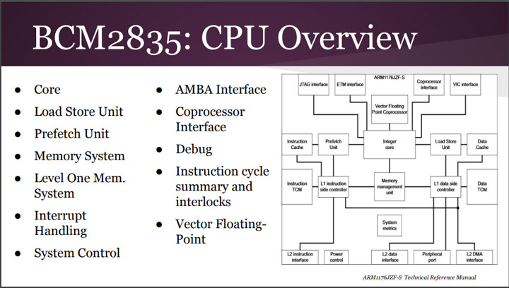
1. CHIP: Broadcom BCM2835 SoC
2. Core Architecture- ARM11
3. CPU: 700 MHz Low Power ARM1176JZFS
4. GPU: Dual Core VideoCore IV® Multimedia Co-Processor
5. Memory: 512MB SDRAM
6. Operating system: Boots from Micro SD card, running a version of the Linux operating system.
7. Dimension: 85 x 56 x 17mm
8. Power: Micro USB socket 5V, 2A
With a CPU configuration reading as:
1. processor belonging to ARM11J6JZF-S (ARM11 Family), having ARMv6 Architecture.
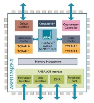
2. Single core, 32-bit RISC(reduced instruction set computer)
3. Having a 700 MHz Clock Rate
Also the following image gives a detail explaination about the components of the core.
we found that there are few some more special features that can be listed as follows:
1. The Fetch stage can hold up to four instructions, allowing for prediction to occur on held instructions, this ensures a break free execution of the program without much of a delay
2. Is able to use dynamic Prediction when there is a history associated with a branch.
3. RPi can play 1080p Blu-Ray quality videos.
4. Graphical capabilities are similar to the those of the original XBOX
Then we tried coding a basic program for blinking an LED.
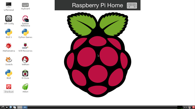
For this we had connected the raspberry pi b+ with keyboards and powered it up, to boot through it.The OS that we had installed was Raspbian , having a pretty simple user interface.
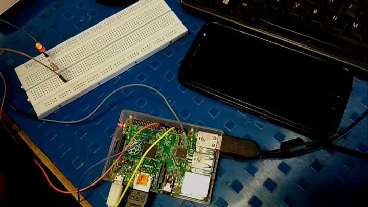
Along with that we had connected an LED to the the GPIO pin of the pi board using a connection on the bread board. Hence our entire circuit appered to be like this.
After this we wrote a test program for blinking the LED in the local text editor in raspbian The code was pretty easy, {Written in python}, explained below.
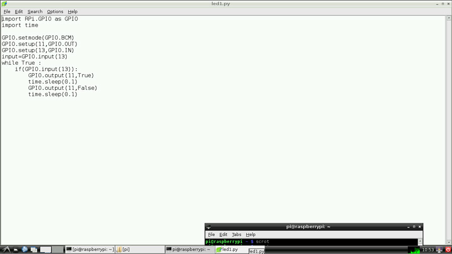
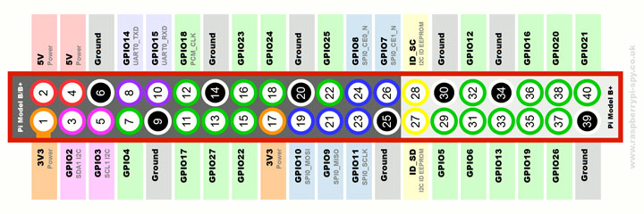
During the compilation the compilation the major challange was to notice the pin that we had plugged the LED onto , and then write the pin number in the code.
This was not quite that difficult but rather confusing because the pins can be assigned. Finally we assigned the numbers in the following order seen here.
Finally we tried to run the program and got the following output.
Learning Outcomes:
This week was fun but hard as well. hard I am saying becouse electronics and programming took lot of time and tested my limitations.I learnt how to read the datasheet and got the chance to learn about the Rpi. I might use that for my project.