Tasks of this week:
The weekly assignment started with the simple tasks:
1. Group Assignment:
Test runout, alignment, speeds, feeds, and toolpaths for your machine.
2.Individual assignment:
Make something big.
What is Machining?
Machining is any of various processes in which a piece of raw material is cut into a desired final shape and size by a controlled material-removal process. The processes that have this common theme, controlled material removal, are today collectively known as subtractive manufacturing, in distinction from processes of controlled material addition, which are known as additive manufacturing.What is CNC:
Computer numerical control (CNC) is the automation of machine tools by means of computers executing pre-programmed sequences of machine control commands. This is in contrast to machines that are manually controlled by hand wheels or levers, or mechanically automated by cams alone.PRSalpha CNC Router:
To complete this assignment We used Shopbot's'PRSalpha CNC Router'Basic Info about shopbot PRSAlpha:
The ShopBot PRS Alpha is a CNC machine that allows users to cut, drill, carve and machine wood, plastic, aluminum and other materials along 3 axes, X, Y, & Z.
Here are the specifications:
1. Table Cutting Dimensions:69 inches x 96 inches.
2. Table Area:
6624 square inches = 46 square feet.
3. Table Thickness:
0.75" Plywood Bottom Layer, 0.75" MDF Top Layer
4. Jog Spindle:
30”(760mm) per second
5. Toolpath:
220V 20A for Controls/ Router (Spindle amperage requirements vary on horsepower and voltage)
6. Software Basic:
PartWorks for making toolpaths and sending gcode machine used Shopbot 3.
This is how The Shopbot's 'PRSalpha CNC Router' looks.

1. group assignment:
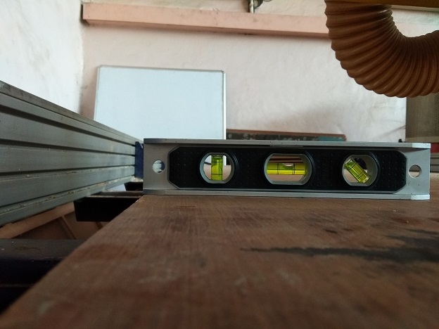
We had a very good dissuction with the lab incharge of the fab lab COEP. The machine is quite of a premitive machine, having an operational software executed over windows XP. For this we decided to make a few test parts to check properties of the machine, which will help us to design our products.1. alignment of the machine is very important in this part. so we decided to check the bed alignment of the machine. The reason behind it was to set the material properly on the bed. After Checking on the spirit level we found a little bit of slant in the alignment.
Second thing was the alignment of the tool:
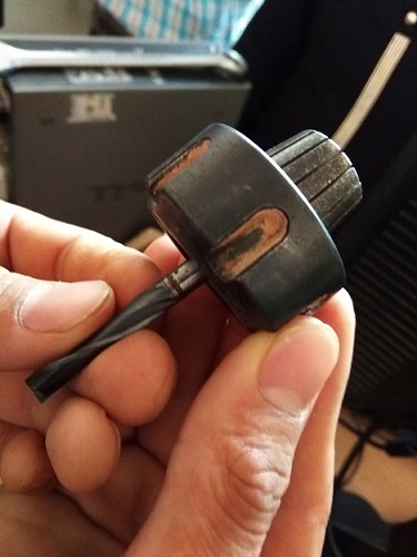
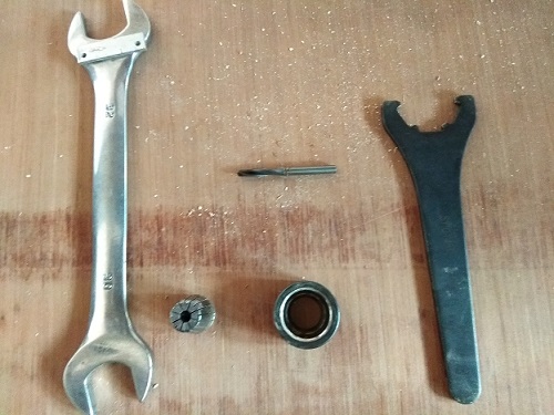
1. A collet:
It is a jaw like structure, when tightend squeases in radially and holds the tool firmly.
2. A shank:
The part on the machine body where the collet along with the tool is inserted.
3. The nut that tightens the collet.
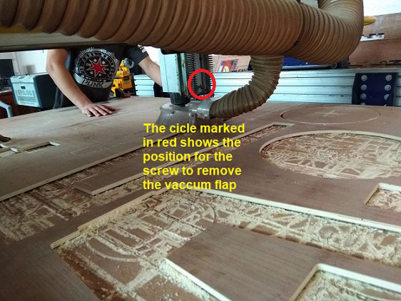
The process for removal is pretty simple:
Initially you loosen the screw of the vaccume curtain, which is behind the z-axix arm, as shown in the figure below
Then we loosen the nut from the shank, with the help of a special groove spanner
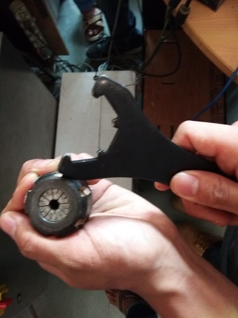
we removed the collet and the tool, and we replaced it with another and re-assemble the collet.
While replacing an exixting tool with a bigger one there are chances of changing the collet too, as it has a fixed tollerance for the size of tool that could fix in
Hence following was the tool assembly
The next thing we learnt was the use of the software.
And after being familier with the machine we made a test part to check the
finish and dimentional error seen on the machine at varrying speed and feed rate.
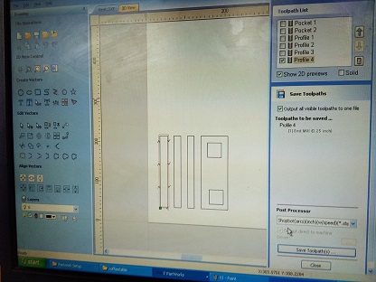
After milling out the part we got a test part that looked like following out
of which we plotted our conclusions necessary for the design purpose.
So finaly after this we came to conclusions:
1. We got this output for the pockets
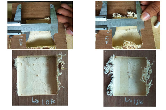
the slot that was milled at the speed of 10k was a better finish as compared
to speed of 12k. this was because excess of speed had ripped of the material instead of cutting it.
2. In the other case where we had milled out the slots, we had got the results as following
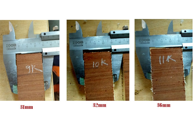
So dimensional error was clearly visible as the seen in the image.
The slots were supposed to be of the width 40mm.
The conclusion was lesser the speed is greater the error, hence we decided to keep a standard spindle speed of 12k RPM to and added the errors in the dimensions of our design.
Something big
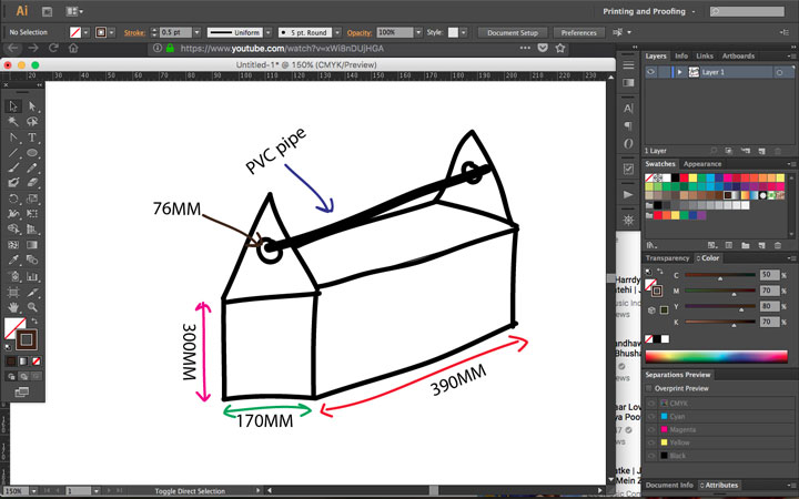
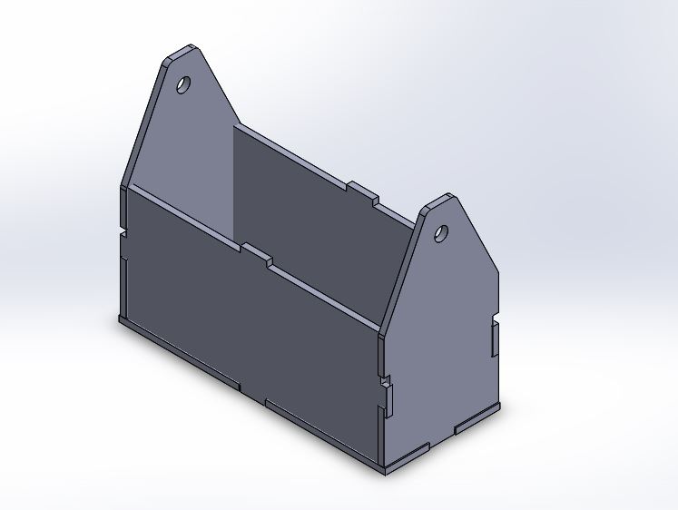
Before Starting with the design I thought of making stool, Laptop stand, Book shelf, Clothing cupbord, Bag stand. After a good brain storming I concentrated on my needs.In vigyan Ashram Whenever some wants work outside that person has to go out with tools. it is very in-convinient to carry all the tools. So I decided to make a toolbox to keep tools. So I made a rough sktech in adobe Illustartor.
Then I started with the main design in solidworks. (Sadly I can not install Solidworks in Apple's Macbook!) So I used one of my friend's Chaitanya Gosavi Laptop to make the design in solidworks. I tried to make it in fusion 360 but I found to make it in solidworks.
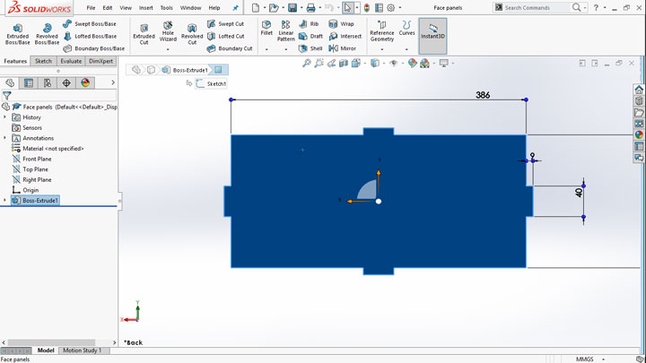
Here I started my design. This is a front pannel.
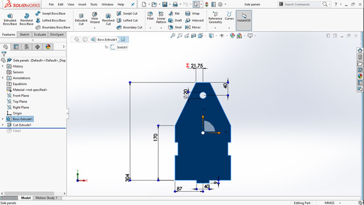
This is a Side pannel.
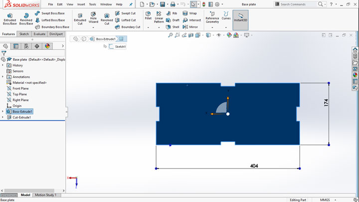
And this one is a base pannel.
The software named partWorks acepts DXF format. I exported all the part work files in .dxf format.
Here is the assembly.
As I wanted to make the tool box very hard I went with 9mm Plywood to make the toolbox. so I seted up the sheet of plywood with clamps.
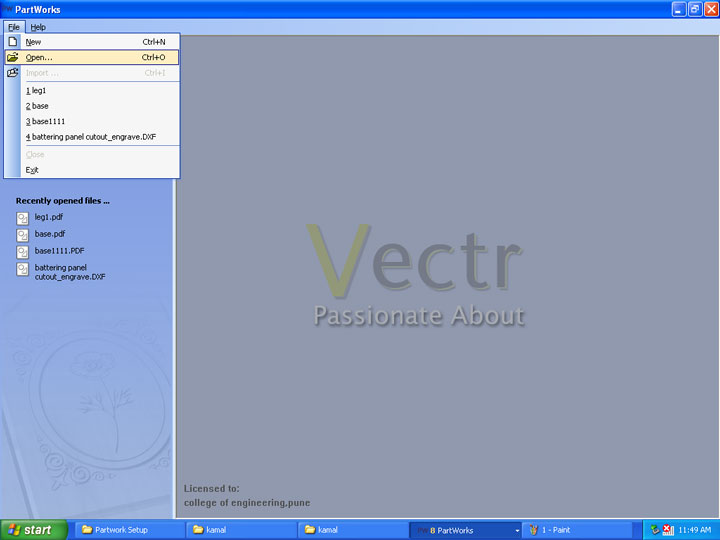
Here is the partworks 3D software which we used to generating toolpaths. The software was running on windows xp.
The software is running on basically vector logics. for 2d cutting I have saved the files in .dxf format.
So the normal curf was 1mm on this machine. I opened the file.
I Set the width 2400mm, height 1200mmm and thickness 9mm of the sheet.
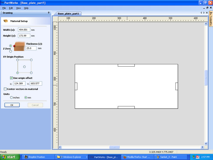
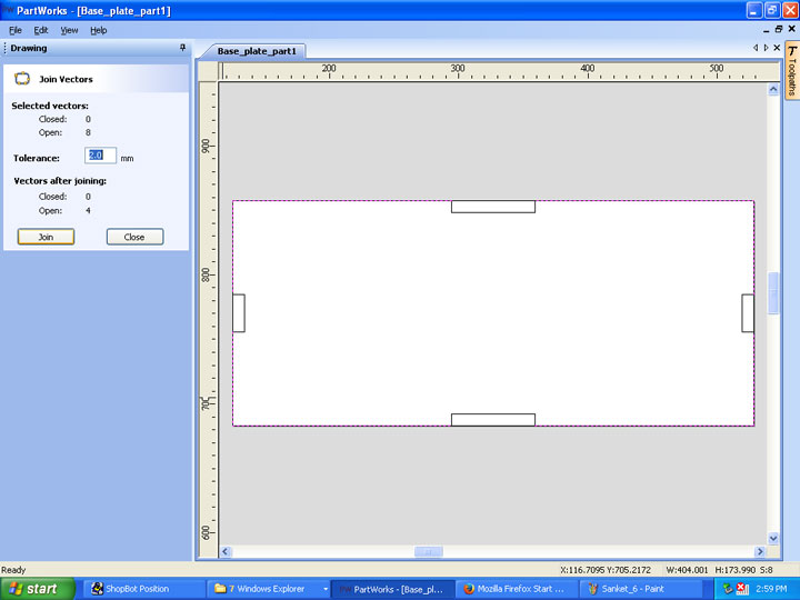
the machine dosen't accept the open vectors so I joined them. It can be done by selecting all lines and by using shift button and click you can join vector option.
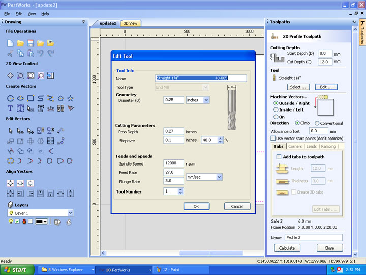
Now here we need to set up the toolpath.
There are two types of toolpaths:
1. The pocketing where the endmill cut the inside part of the path it traverses.
2. The profiling where the endmill cuts the outside of the path it traverses.
So in the design I was having both profiling toolpaths. Save and check the tool paths.

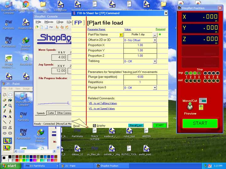
After that I opened the shopbot editor software. clicked on preview button. as you can see I set the all the axies.
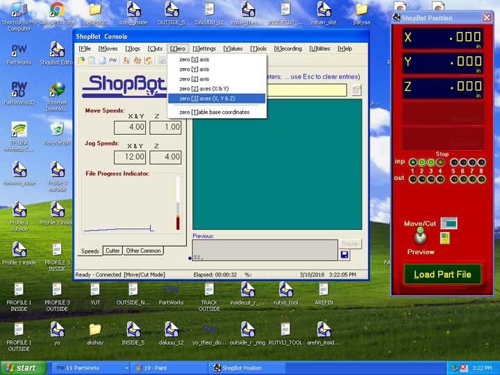
It was time to start the machine. seafty is always better than anything. I set the bed by using clamps.
frist I turned ON the vaccum who sucks and store the cutted wood.
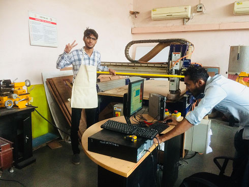
I set the Z axis and cutting tool. while setting up the tool we need to make sure that the tool has set up correctly. Otherwise tool can get damage and your material too. The Z axis and the tool was already set becouse all of use went to college of engginering, Pune to use shopbot. After this I loaded the part file and sent to the machine and machine started to cut.
I started to assemble my tool box.

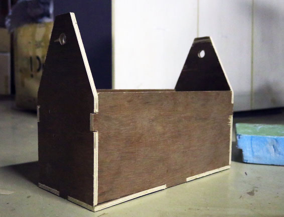
And here it is!! this is how it looks.

This was a before toolbox.
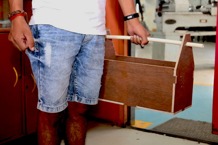
And now this is how it has been using by many people.

Learning Outcomes: In this assignment I learnt about CNC machining and designing. How you can make which is usefull and easy to make. I also learnt about managing the things.
You can Download the Files.