Tasks of this week:
The weekly assignment started with the simple tasks:
1. Group assignment:
characterize your lasercutter, making test part(s) that vary cutting settings and dimensions.
2. Individual assignment:
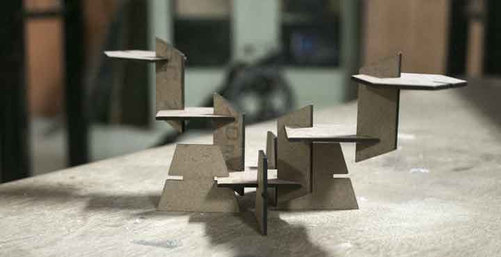
cut something on the vinylcutter design, lasercut, and document a parametric press-fit construction kit, accounting for the lasercutter kerf, which can be assembled in multiple ways.
1. group assignment:
characterize your lasercutter, making test part(s) that vary cutting settings and dimensions.
A 2d design draws 2-dimensional, or flat, images used in mechanical drawings, electrical engineering projects, video games, animation, clothing construction and architecture. 2d design use a combination of drawing skills and computer-aided drafting technology to create images for plans, brochures, websites and other products.
This week we had group assignment, this may cause the same image to appear on pages of multiple students.
For this task we had a group assignment where we had to study about the properties and kurf of the laser engravers, for that we splitted ourselves into two groups, each assigned with one machine, and we had to explain our tasks and conslusions to others. The conslusions of each assignment for insividual machine are written below its properties.For this we made two patterns in which we once kept a constant speed, and later constant power, to measure the difflection in the kurf.
For this to make our work easy we used colour mapping where we added colour to the boundary, and specified it's properties individually.
There are few more steps required inoder to worl with epilog, which are mentioned below:-
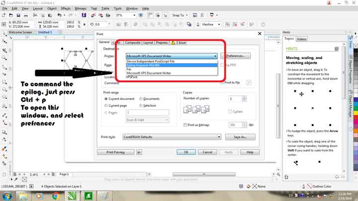
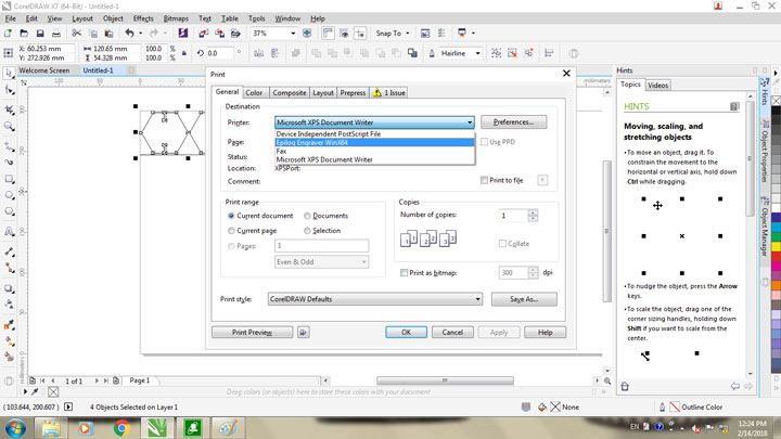
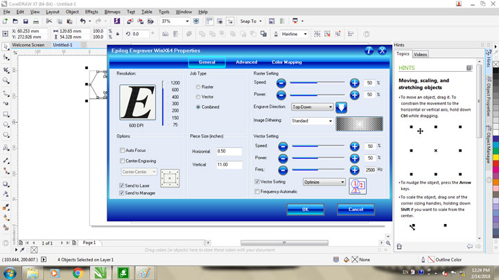
1. Once done with the adjustments of the design hit Ctrl + P, to open a menu as shown below, and follow the steps in the image.
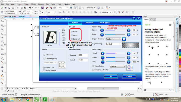
2. Once done with that select prefrences to get a menu as shown below and manipulate the parameters (guided in the image) as required.
3.Then just hit enter, set the origin on the engraver manually and press go.
Hence we made patterns for kerf calculation and got following results for individuals:
MDF:- For this we decided to keep the power constant, and varry the speed between
the range of 30 to 60 percent as shown in the image about colour mapping.
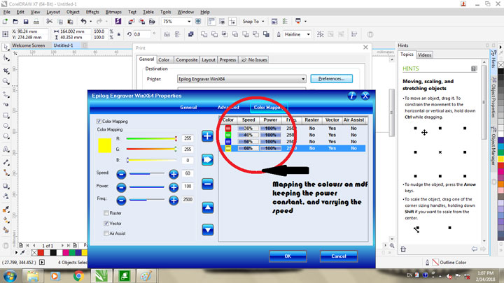
The following were the results we recived about the difflection in the kurf.
Out of which we concluded that 100% power and 50% speed was ideal for minimal kurf of 0.14mm.
Acrylic:- For this assessment we did the same where we used same shapes of 40mm X 40mm with changing colour maps, as shown below.
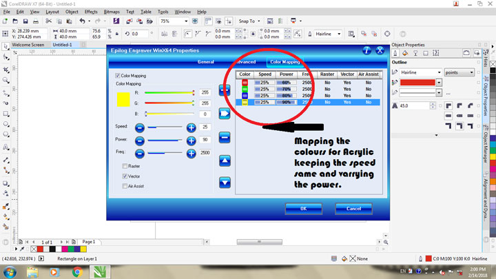
For this we had to feed the machine with multiple passes, which actually exceeded upto 8 passes, for the powers and speeds we wanted to test After 7 to 8 passes we got the cut outs to produce following results.

Out of which we concluded that at a speed of 25%, the ideal power is 80% to achieve a kurf of 0.13mm.
2. Individual assignment:
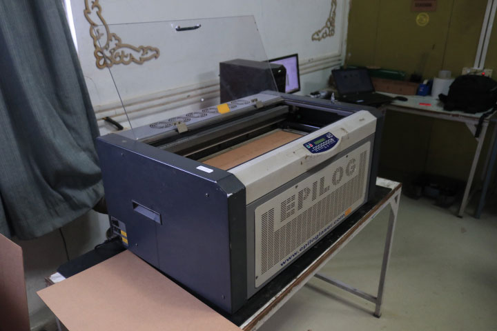
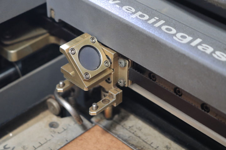
Epilog Mini 24 Laser:
Move up to the Mini 24 for a larger work area (24" x 12") that holds most standard engraving stock material. The large work area will hold many standard engraving material sheets. Normally we can cut and engrave acrylic, cardboard, balsa wood in different thickness.
This is a mirror which reflects the laser from its source point to the nozzel.
As we were learning what is Parametric design I sreached on google and I came to know that:
Parametric design is a process based on algorithmic thinking that enables the expression of parameters and rules that, together, define, encode and clarify the relationship between design intent and design response.
So I made somde paramatric design in solidworks.
saved as .dxf format.
To laser cut them I opend all the .dxf files in corel draw and changed thier thickness to Hairline.
I changed the thickness to hairline becouse I wanted to cut it through.
To cut them I followed the process by selecting the epilog engraver
After that I went to preferences and put the parameters according to my material.
here I am going to use MDF so Set the power, speed and frequancy as per MDF.
I selected vector to cut the part through and gave the Speed=30% Power=90% and
I kept frequancy to automatic.
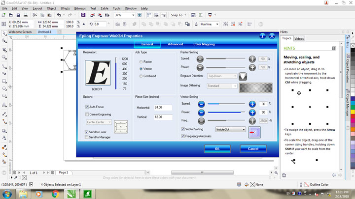
clicked on okay. and gave the go command from Laser cutter.
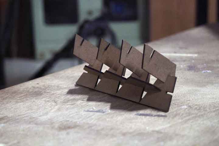
Finally Done with the laser cutter.
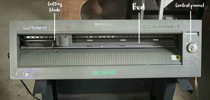
Vinyl cutter:
A vinyl cutter is a type of computer-controlled machine. Small vinyl cutters look like computer printers. The computer controls the movement of a sharp blade like a knife. This blade is used to cut out shapes and letters from sheets of thin self-adhesive plastic (vinyl). The working area of it is 700mm.
The logic behind vinyl cutter is like a paper cutter where you have to apply speed and power as per your rquirements. Similarly here also you have to control the speed and power according to your material.
I am going to cut a sticker. I have made the design in the Adobe Illustratior. I have saved that file in .png format.

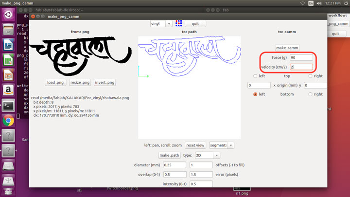
to use vinyl cutter we use the fab module through linux, because the drivers are formatted in the initial system.
Here are the steps to use the fab module.
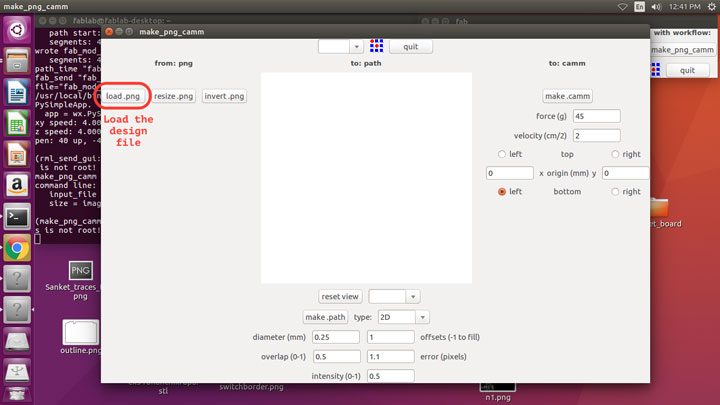
1. Import the image
(Note:- The image required is in *.png format, and has to be of high resolution in order to get a fine cut)
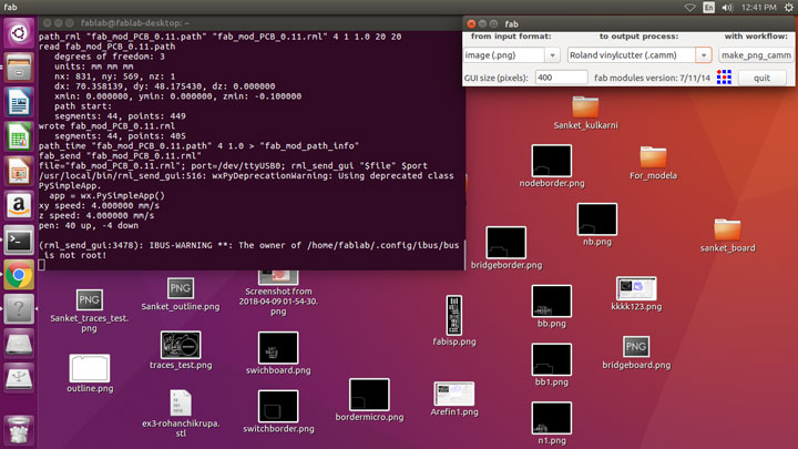
2. Generate the path. Put the speed and force (Force - 90gf and Speed - 2)
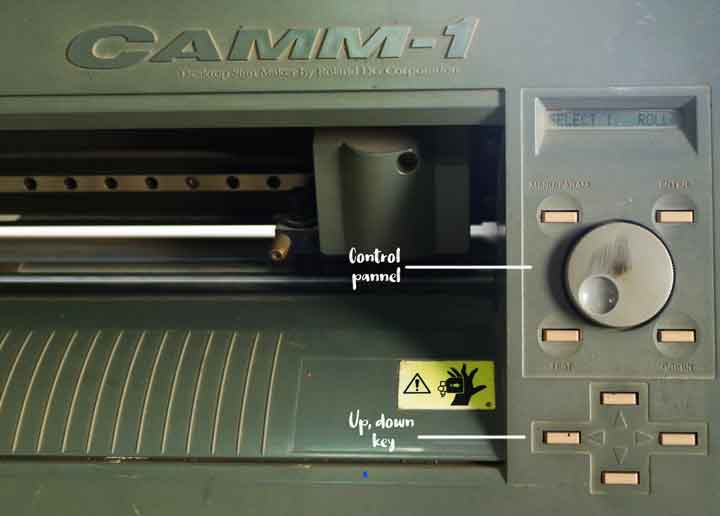
we need to set the vinyl paper from backside.
After setting up the roll we need to set the force and according to our sheet.

After setting up the vinyl sheet I set the force, speed and origin using the control pannel.
Then I Sent the image as a tool path to the cutter. I put the force 90f and speed 2. clicked on make.camm and sent to the machine to cut.
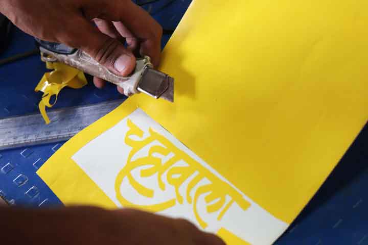
For taking out the cutted part I drew a outline box in my design to take it out properly.
After cutting the design I peeled out the outer box. and applied the masking tape on it
to pulled up. sticked it.
while peeling it out by misktake I peeled out the last part of the design. you can see in the image.
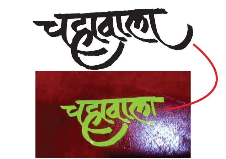
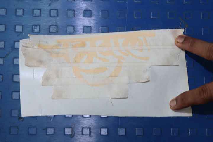
I peeled it out and sticked on a vinyl corrner where we stick all our designs in fablab 0.
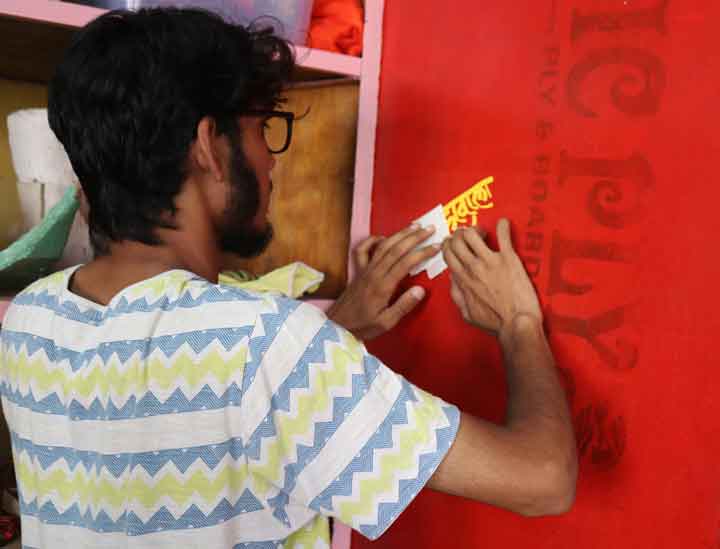
Yey!!! Here is the final sticker.