Tasks of this week:
The weekly assignment started with the simple tasks:1. Group assignment:
measure the power consumption of an output device.
2. Indivisual:
add an output device to a microcontroller board you've designed, and program it to do something.
What are output devices?
An output device is any device used to send data from a computer to another device or user. Most computer data output that is meant for humans is in the form of audio or video. Thus, most output devices used by humans are in these categories. Examples include monitors, projectors, speakers, headphones and printers.
Types of Sensors.
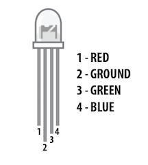
1. RGB LED:
RGB LED means red, blue and green LEDs. RGB LED products combine these three colors to produce over 16 million hues of light. Note that not all colors are possible. Some colors are “outside” the triangle formed by the RGB LEDs. Also, pigment colors such as brown or pink are difficult, or impossible, to achieve.
2.LCD:
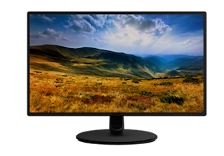
A liquid-crystal display (LCD) is a flat-panel display or other electronically modulated optical device that uses the light-modulating properties of liquid crystals. Liquid crystals do not emit light directly, instead using a backlight or reflector to produce images in color or monochrome. LCDs are available to display arbitrary images (as in a general-purpose computer display) or fixed images with low information content, which can be displayed or hidden, such as preset words, digits, and seven-segment displays, as in a digital clock. They use the same basic technology, except that arbitrary images are made up of a large number of small pixels, while other displays have larger elements.
3.DC motor:
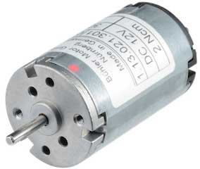
A DC motor is any of a class of rotary electrical machines that converts direct current electrical energy into mechanical energy. The most common types rely on the forces produced by magnetic fields. Nearly all types of DC motors have some internal mechanism, either electromechanical or electronic, to periodically change the direction of current flow in part of the motor.e is dependent on temperature, more so than in standard resistors. The word is a portmanteau of thermal and resistor.
4.Servomotor:
A servomotor is a rotary actuator or linear actuator that allows for precise control of angular or linear position, velocity and acceleration. It consists of a suitable motor coupled to a sensor for position feedback. It also requires a relatively sophisticated controller, often a dedicated module designed specifically for use with servomotors.

5. Stepper Motor:
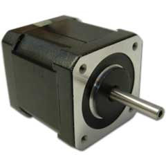
A stepper motor or step motor or stepping motor is a brushless DC electric motor that divides a full rotation into a number of equal steps. The motor's position can then be commanded to move and hold at one of these steps without any position sensor for feedback (an open-loop controller), as long as the motor is carefully sized to the application in respect to torque and speed.
1. Group assignment:
The task that we had this week was to check the power cosumption of the devices that we used.This is a very important factor when there is a need of optimisation in any point of the machine, the analysis of this gives you a detailed idea about the setup that you have and about the setup that you could optimise. For this we had taken devices into consideration one being a 5V DC motor, and the other was a 12V DC water pump.
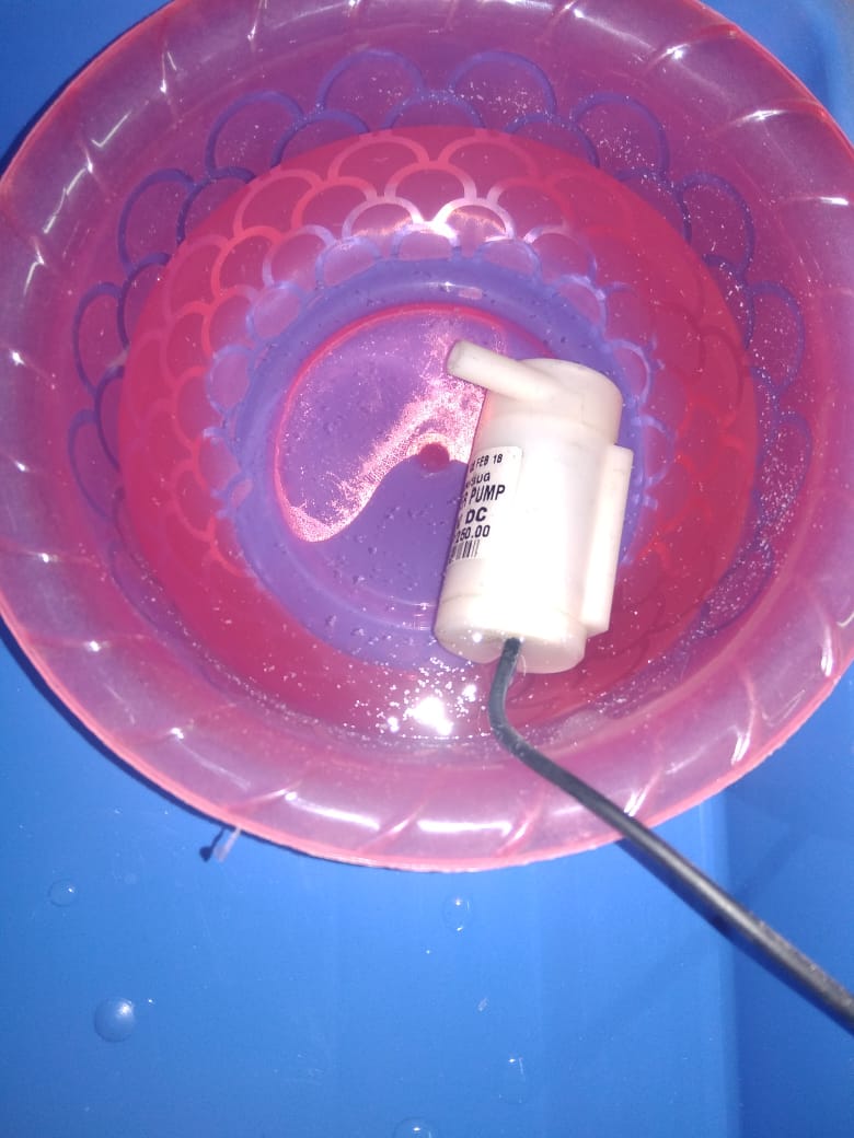
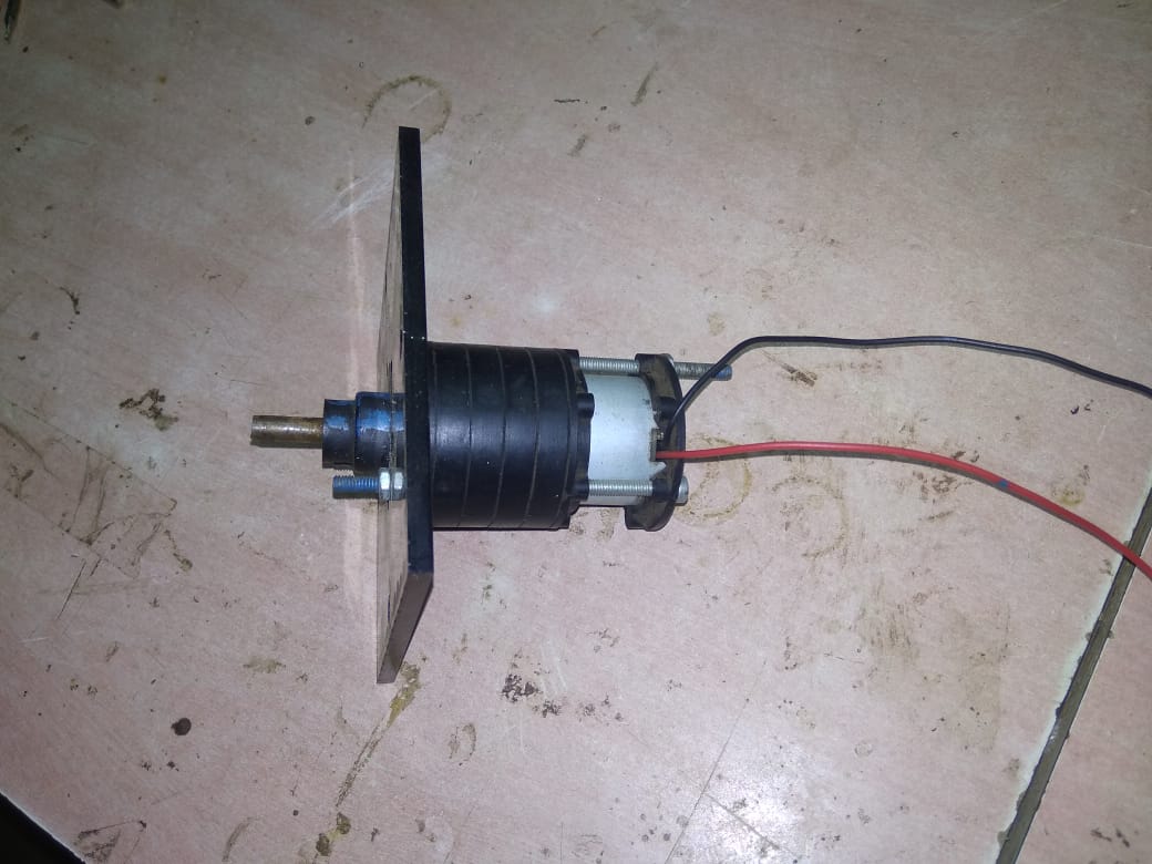
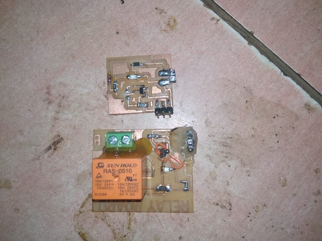
The operational setup was a processor board connected on one side through the arduino, an output device out of the ones stated above, directed through the relay. For the operations we had two sets of relay, one being just guided by a mosfet cosidering the lower power ratings needed, and the other was one having physical relay cosidering the higher power ratings needed.
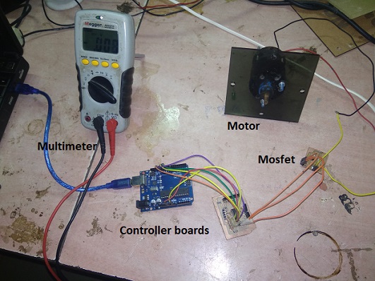
For testing the power consumption we had made a setup as seen in the image below, consisting of a 5V DC motor, a mosfet, controller board, arduino.
The code fed to the board was basic blink code with a delay of 5sec, that would give us significant time to anyalyse what was happening. Hence we fed the code and got the setup working, that gave us following results, as seen in the video below.
Also here both the parameter for the calculation of power ( voltage and current), were supposed to be calculated manually using a multimeter, which was once to be setup in series (for getting the current), once in parallel(to get the voltage)
With similar we got the following reading of voltage and current.
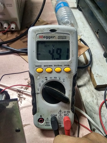
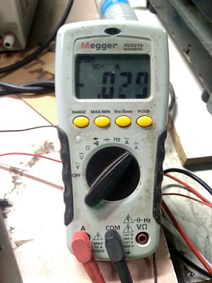
The next thing left was just to calculate the power consumption using a simple formula of P=VI, that explains as power = voltage * current.
Hence considering our reading our motor had a power consumption of 0.1423 Joules
The next thing to work with was the water pump. For this the setup that we had was a relay, operated by a controller board, an external power supply, and a 12V dc water pump.
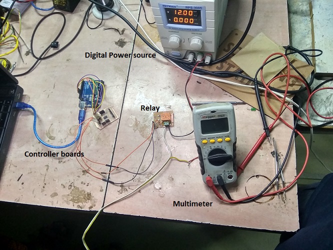
The code that we were supposed to use was the same, which we burnt and got the circuit working as seen here.
Here fortunately the digital power supply was capable to directly show the readings of the voltage and current.
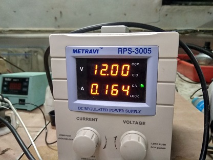
Hence after this the only task was to calculate the power consumption using the same formula as mentioned above. Considering the same the power consumption of our water pump was 1.968 Joules.
Indivisual assignment:
add an output device to a microcontroller board you've designed, and program it to do something. In this assigment I decide to go with Servo motor. I want to use the servo motor in my final project. I started seraching online about servo motor.
I found a data sheet datasheet of 'Servo motor'
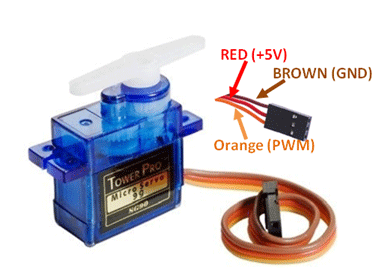
after that I started to design the board according my requirenments.
following things I am going to use in my board:
1. 20 MHz Crystals
2. Attiny 44-SSU
3. 10k resistor
4. 22uf capacitor
5. 7805 regulator
6. 2x2 pin header
7. 3x3 pin header
Here I started designing my board.
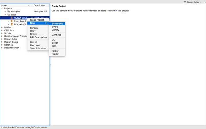
I added attiny45.
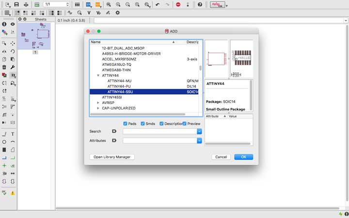
Then I selected capacitor.
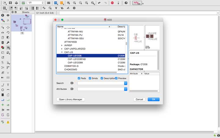
Then I added resistor.

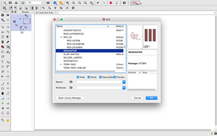
Here I selected the resonator.
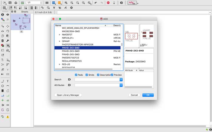
2x2 pin header.
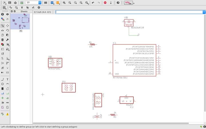
This is schematic of my board.
This is how my board looks.

After that I saved it as .png format and imported into fab modules.
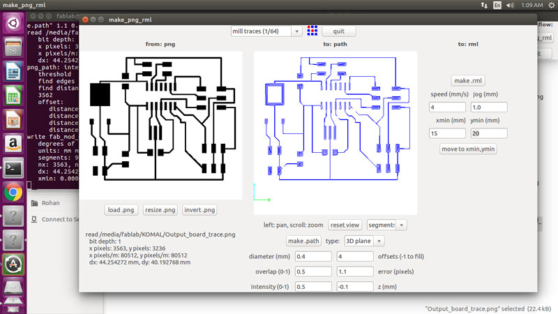
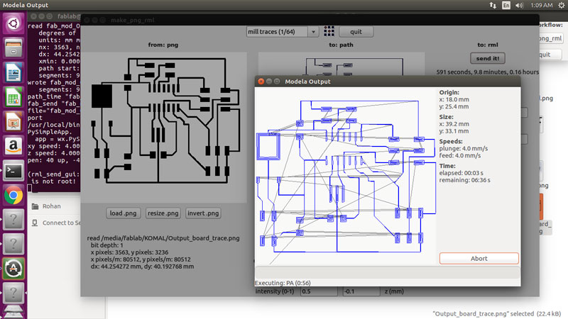
And I began the milling.
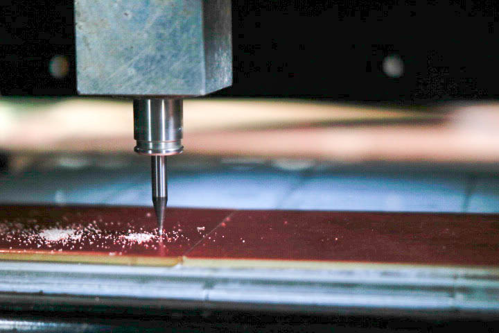
After milling the board I soldered it. this is how it looks after soldering.

Now the programming parts comes.
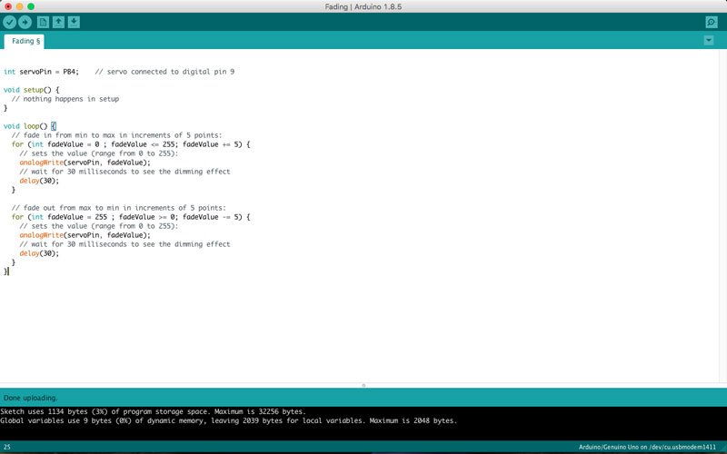
as per my instructor's instrucation to run the servo motor I opend the ardiuno IDE. In the Examples I opend Analog and selected the fading code.

As per my board diagram I conected the fabISP to my output board. and conected the board to servo motor.

I refered the data sheet of servo motor and I understood the connections. as per that I changed the servo pin.
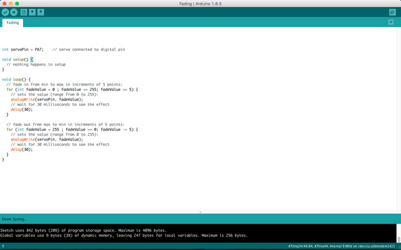
I selected the Attiny 44 as a processor, clock Internal 8MHz, selcted the port and lastly programmer as USBtinyISP and burned the bootloader.
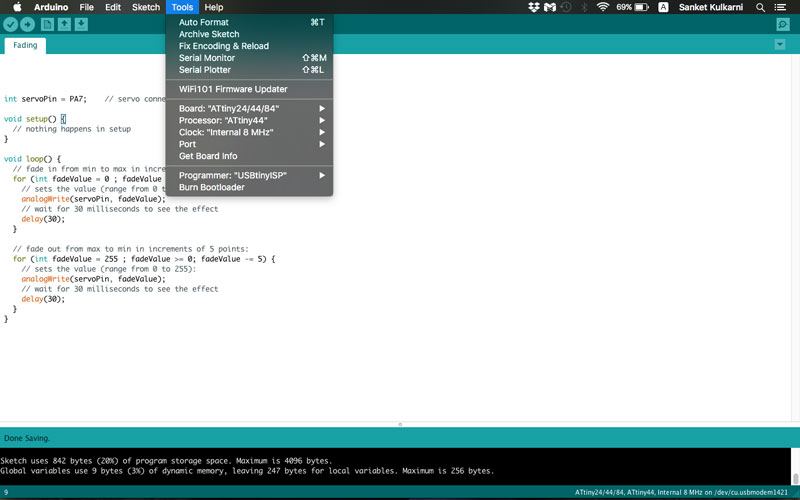
After that I verified the code and updated it into my board.
Bingo!! My servo motor started working. Here is the video.
You can Download the Files.
Learning Outcomes:
I learnt about servo motor. how the connections are work. Now I can work with servo motor easily.