Tasks of this week:
The weekly assignment started with the simple tasks:1. Group assignment:
measure the analog levels and digital signals in an input device
2. Indivisual:
measure something: add a sensor to a microcontroller board that you have designed and read it
What are input devices?
An input device is a piece of computer hardware equipment used to provide data and control signals to an information processing system such as a computer or information appliance. Examples of input devices include keyboards, mouse, scanners, digital cameras, And also some sensors which can sense the motion, distance, light.
Types of Sensors.
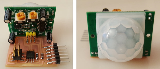
1. Motion Sensor:
A motion sensor is a device that sense moving objects, particularly people.
Such a sensor is often integrated as a component of a system that automatically performs a
task or alerts a user of motion in an area.
2.Ultrasonic Sensor:
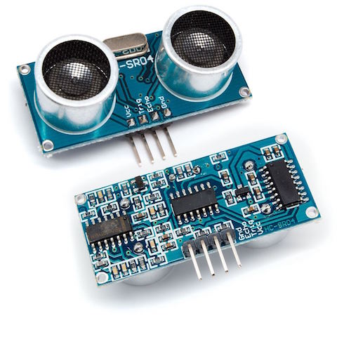
An Ultrasonic sensor is a device that can measure the distance to an object by using
sound waves. It measures distance by sending out a sound wave at a specific frequency
and listening for that sound wave to bounce back.
3.Thermistor:
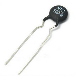
thermistor is a type of resistor whose resistance is dependent on temperature,
more so than in standard resistors. The word is a portmanteau of thermal and resistor.
4.Phototransistors:
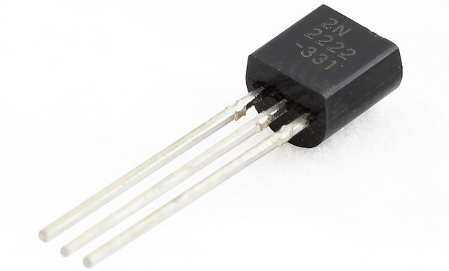
Phototransistors are either tri-terminal (emitter, base and collector) or bi-terminal
(emitter and collector) semiconductor devices which have a light-sensitive base region.
Although all transistors exhibit light-sensitive nature, these are specially designed
and optimized for photo applications.
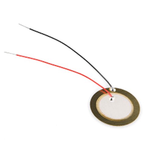
5. Piezoelectric sensor:
Piezoelectric sensor is a device that uses the piezoelectric effect, to measure
changes in pressure, acceleration, temperature, strain, or force by converting
them to an electrical charge. The prefix piezo- is Greek for 'press' or 'squeeze'
1. Group assignment:
In group assignment we have to measure digital signals and analog level of an input device. in our group 3-4 people were working on the temperature sensor i.e LM35 as a input device.SO here we checked signals/output for the temperature sensor with the help of CRO, after adjusting the volts/div and increasing the time duration to around 2-10secs we were able to observe the output.
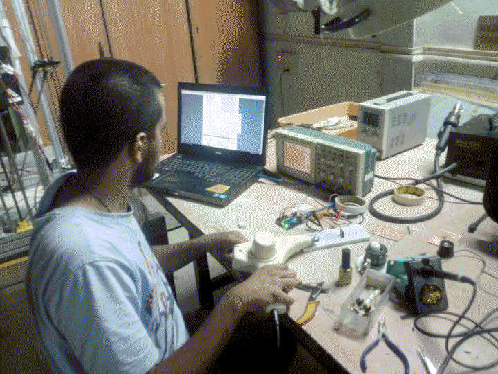
we used a heat gun to test the rise in temperature.

This basically helped us to understand how we should write the code.
Indivisual assignment:
In this assigment I decide to go with Ultrasonic HC-SR04 sensor. I found it very intresting. it looks so attractive. As all this things are new to me I startedresearching online.

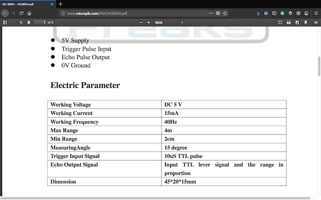
As per my instructor's guidence I refered a datasheet
for 'Ultrasonic HC-SR04' you can get the datasheet here.
after that I started to design the board according my requirenments.
following things I am going to use in my board:
1. Ultrasonic HC-SR04 sensor
2. Attiny 45SI
3. 10k resistor
4. 1mu capacitor
5. 499k resistor
6. LED
7. FTDI
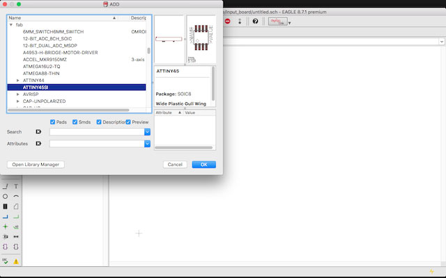
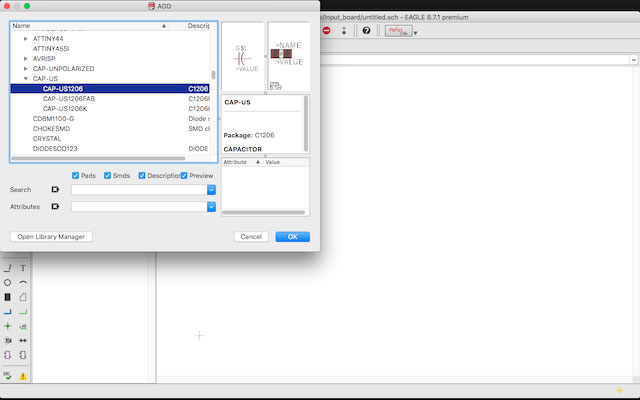
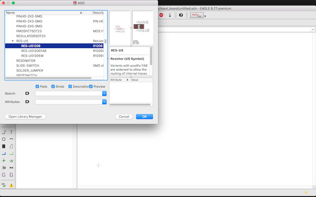
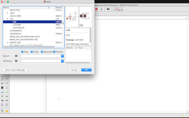
Here I started designing my board. I added the components from fab library.
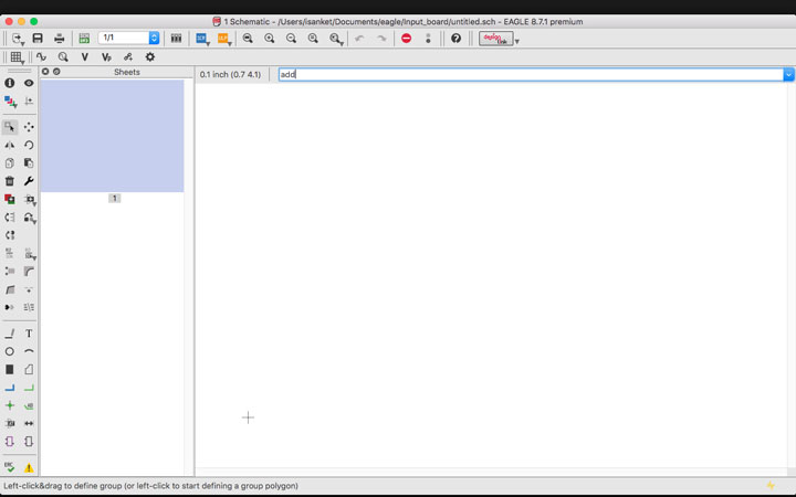
I added attiny45.
Then I selected capacitor.
Now here I selected resistors.
And I added the LED.
After adding all the components I started arrenging the schematic.
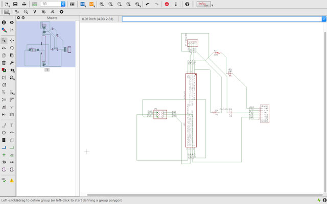
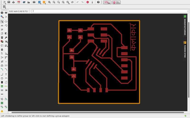
After Arrenging the schematic I expoeted the board as .png
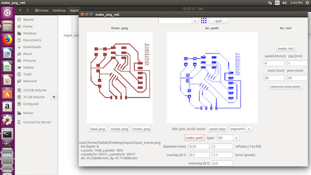
After making the .png file I imported it in fab module.
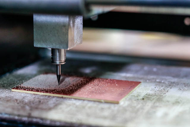
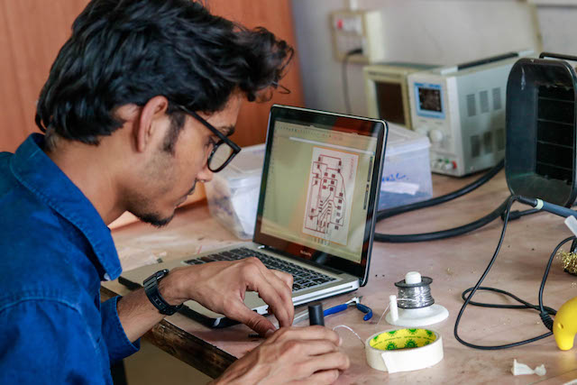
Modela while milling the board
after milling I started soldering the board
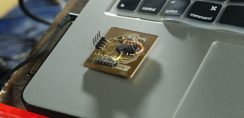
This is how it looks after soldering the board.
as I have very less knowlage about coding and programming I took help for program from my instructor.
Here is the code for ultrasonic sensor.
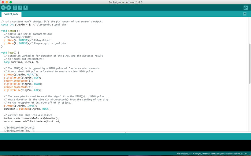
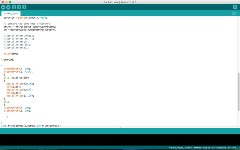
To program the board I conected my board to the ardiuno. loaded the program. This is the program. I selected the IC ATtiny 45. Processor and port and burned the bootloder.
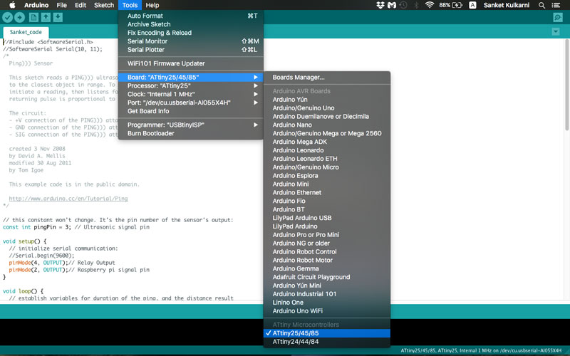
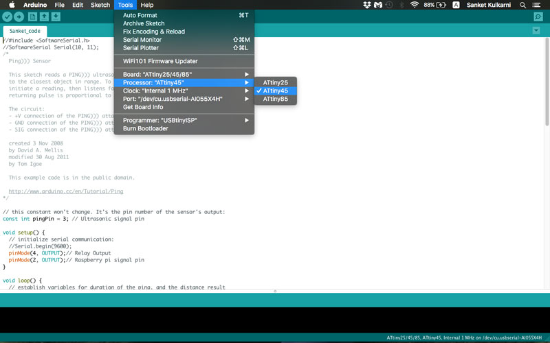
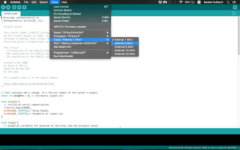
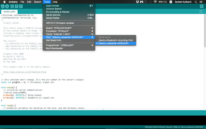
after that I verified the code and compiled it.
Here is the result I got.
You can Download the Files.
Learning Outcomes:
I learnt about ultrasonic sensor. how it works and how we can use it. I might be using this sensor in my final project.